EP0961361B1 - Elektrische Verbinderbaugruppe mit einem Hebel zum Unterstützen eines Zusammenfügens - Google Patents
Elektrische Verbinderbaugruppe mit einem Hebel zum Unterstützen eines Zusammenfügens Download PDFInfo
- Publication number
- EP0961361B1 EP0961361B1 EP99110364A EP99110364A EP0961361B1 EP 0961361 B1 EP0961361 B1 EP 0961361B1 EP 99110364 A EP99110364 A EP 99110364A EP 99110364 A EP99110364 A EP 99110364A EP 0961361 B1 EP0961361 B1 EP 0961361B1
- Authority
- EP
- European Patent Office
- Prior art keywords
- lever
- connector
- electrical connector
- latch
- mating
- Prior art date
- Legal status (The legal status is an assumption and is not a legal conclusion. Google has not performed a legal analysis and makes no representation as to the accuracy of the status listed.)
- Expired - Lifetime
Links
- 230000013011 mating Effects 0.000 title claims description 50
- 230000000295 complement effect Effects 0.000 claims description 3
- 229910052782 aluminium Inorganic materials 0.000 description 2
- XAGFODPZIPBFFR-UHFFFAOYSA-N aluminium Chemical compound [Al] XAGFODPZIPBFFR-UHFFFAOYSA-N 0.000 description 2
- 238000010586 diagram Methods 0.000 description 2
- 239000007769 metal material Substances 0.000 description 2
- 238000000034 method Methods 0.000 description 2
- 230000002093 peripheral effect Effects 0.000 description 2
- 238000004512 die casting Methods 0.000 description 1
- 210000004124 hock Anatomy 0.000 description 1
- 238000003780 insertion Methods 0.000 description 1
- 230000037431 insertion Effects 0.000 description 1
- 238000012423 maintenance Methods 0.000 description 1
- 239000000463 material Substances 0.000 description 1
- 230000007246 mechanism Effects 0.000 description 1
- 229910052751 metal Inorganic materials 0.000 description 1
- 239000002184 metal Substances 0.000 description 1
- 238000005192 partition Methods 0.000 description 1
- 238000007789 sealing Methods 0.000 description 1
- 229910001220 stainless steel Inorganic materials 0.000 description 1
- 239000010935 stainless steel Substances 0.000 description 1
Images


Classifications
-
- H—ELECTRICITY
- H01—ELECTRIC ELEMENTS
- H01R—ELECTRICALLY-CONDUCTIVE CONNECTIONS; STRUCTURAL ASSOCIATIONS OF A PLURALITY OF MUTUALLY-INSULATED ELECTRICAL CONNECTING ELEMENTS; COUPLING DEVICES; CURRENT COLLECTORS
- H01R13/00—Details of coupling devices of the kinds covered by groups H01R12/70 or H01R24/00 - H01R33/00
- H01R13/62—Means for facilitating engagement or disengagement of coupling parts or for holding them in engagement
- H01R13/629—Additional means for facilitating engagement or disengagement of coupling parts, e.g. aligning or guiding means, levers, gas pressure electrical locking indicators, manufacturing tolerances
- H01R13/62933—Comprising exclusively pivoting lever
Definitions
- This invention generally relates to the art of electrical connectors and, particularly, to an electrical connector assembly wherein a lever is used to assist in mating a pair of connectors.
- EP-A-0 725 461 which in considered as the closest prior art, concerns a lever type connector assembly in which the process of attaching a torsion coil spring to a lever can be simplified.
- the torsion coil spring is disposed between the lever and the connector in order to bias the lever in a given rotary direction relative to the male connector housing.
- the coil's restoring force acts in such a way that the coil causes the movement of the lever to release the mating connector.
- the present invention is directed to solving one or more of the problems discussed above.
- An object, therefore, of the invention is to provide an electrical connector assembly with a new and improved mating assist lever system.
- the assembly in the exemplary embodiment of the invention, includes a connector having a housing adapted for mating with an appropriate complementary mating connector.
- a lever pivot post is fixed to and projects from the housing.
- a lever is pivotable about the pivot post between operative and inoperative positions for mating and unmating the connectors.
- the lever includes an aperture embracing the pivot post. The aperture is larger than the post to allow for lost motion between the lever and the post.
- the lever includes a latch portion engageable with the mating connector for drawing the connectors into mated condition in response to rotating the lever about the pivot post from its inoperative position to its operative position.
- a spring is operatively associated between the lever and the pivot post to bias the lever in the mating direction of the mating connector when the lever is in its operative position.
- the spring also biases the mating connector into a fully mated position.
- the spring is generally U-shaped with a distal end of one leg fixed to the lever and a distal end of an opposite leg fixed to the pivot post.
- the housing includes a cover having the pivot post thereon and on which the lever is mounted.
- the lever is generally U-shaped and straddles the housing or cover, with a pair of lever arms on opposite sides of the cover pivotable about a pair of pivot posts at opposite sides of the cover. At least one of the springs is operatively associated between each one of the lever arms and one of the pivot posts.
- the latch portion of the lever is located at one side of the pivot post, and the spring is located at an opposite side of the pivot post.
- the latch portion of the lever is formed as a latch hook for engaging a latch projection on the mating connector.
- a feature of the invention is directed to the provision of an enlarged detent recess at a base of the latch hook and into which the latch projection of the mating connector "snaps". This gives an audible and tactile indication of the fully mated position of the mating connector.
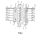
- Figure 1 shows a somewhat schematic or block diagram of the termination system afforded by the connector assembly of the invention.
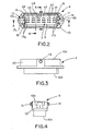
- Figures 2-6 show the receptacle connector of the connector assembly.
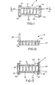
- Figures 7-10 show one of the identical connector modules that are used in both the plug connector and the receptacle connector of the assembly.
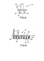
- Figures 11-15 show the plug shell of the plug connector.
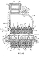
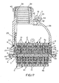
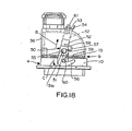
- Figures 16-18 show the entire connector assembly including both the receptacle connector and the plug connector.
- the connector assembly of the invention is readily applicable for use in such applications as robotic applications involving machine tools, assembly apparatus and the like, which may be encountered in the automotive industry, for instance.
- the left-hand side of Figure 1 might represent a controlled side of a machine tool such as a robot main body
- the right-hand side of Figure 1 might represent a control equipment side such as a controller.
- the controlled side at the left of Figure 1 includes a plurality of wires 1 divided into six groups "g1-g6".
- the six groups of wires 1 are terminated to six identical connector modules, generally designated 2.
- the right or control equipment side of Figure 1 shows a plurality of wires 3 in six groups "g1-g6", with the wires in each group terminated to identical connector modules, generally designated 2. All of connector modules 2 on both the left and right sides of the termination system can be identical in structure and configuration.
- a first or receptacle connector includes a plurality of terminal pins 5 mounted through an insulative or dielectric wafer 6 to form a wafer assembly 7 within receptacle connector 4.
- the pins are arranged in six clusters "b1-b6".
- the six connector modules 2 terminated to the six groups of wires 3 on the control equipment side are mounted in a plug shell 8 of a second or plug connector, generally designated 9.
- group "g1" of wires 1 terminated to connector module 2 on the left or controlled side of the system are connected through terminal pins "b1" of receptacle connector 4 to wires 3 in group “g1” terminated in one of the connector modules 2 of plug connector 9, and so on through groups "g2-g6" of wires in the system.
- Figures 2-6 show plug connector 4 (Fig. 1) with dielectric wafer 6 and terminal pins 5 mounted within a generally rectangular outer housing 10.
- the housing is fabricated of die cast metal material, such as aluminum.
- Wafer assembly 7, including wafer 6 and terminal pins 5, is secured within the housing by locking pins 11 (Fig. 6).
- the terminal pins are arranged in six clusters of six pins corresponding to clusters "b1-b6" as described above in relation to Figure 1.
- housing 10 of receptacle connector 4 defines a terminal face 10a and a mating face 10b.
- Six identical module-receiving receptacles 12 (Fig. 5) are formed in termination face 10a for receiving six connector modules 2 (Fig. 1).
- a generally rectangular plug-receiving receptacle 13 is formed in mating face 10b for receiving a plug portion of plug shell 8 (Fig. 1) of plug connector 9, as described hereinafter.
- Terminal pins 5 are mounted through wafer 6 as best seen in Figures 5 and 6 and include mating ends 5a projecting into plug-receiving receptacle 13 and connector ends 5b projecting into module-receiving receptacles 12.
- a latch post 15 projects outwardly from each opposite side of housing 10 of receptacle connector 4 for purposes described hereinafter.
- a polarizing recess 16 is formed in three corners of receptacle 13. The recesses are in the form of grooves extending in the mating direction of the connectors.
- a grounding clip 17 (Fig. 2) is mounted at each opposite end of housing 10 of receptacle connector 4 as will be described in greater detail hereinafter.
- Figures 7-10 show one of the connector modules 2 (Fig. 1) which are inserted into receptacles 12 (Fig. 5) of receptacle connector 4.
- the connector modules also are mounted in plug shell 8 (Fig. 1) of plug connector 9 as described hereinafter. It should be understood that the terminals have been removed from module 2 in Figures 7-10 to avoid cluttering the illustration.
- each module 2 includes an insulative or dielectric housing, generally designated 18.
- the housing includes a plurality of terminal-receiving passages 19. Six passages are provided corresponding to the six terminal pins in each of the clusters of pins "b1-b6" (Figs. 1 and 2).
- Housing 18 defines a connecting or mating end 20 and a termination end 21. The mating end is inserted into one of the module-receiving receptacles 12 (Fig. 5) of receptacle connector 4, and electrical wires 1 (Fig. 1) are terminated to female terminals inserted into passages 19 through termination end 21.
- a pair of cantilevered latch arms 23 are provided at opposite ends of housing 18.
- the latch arms have chamfered latch projections 24 which latch behind latch shoulders 25 (Fig. 5) within receptacles 12 of receptacle connector 4.
- Key grooves 26 are formed in opposite sides of housing 18 for receiving keying ribs 27 (Fig. 5) within receptacles 12 of receptacle connector 4 to polarize the modules and the receptacles so that the modules can be inserted into the receptacles in only given preselected orientations.
- plug shell 8 of plug connector 9 (Fig. 1) is shown in detail.
- the plug shell is formed of die cast metal, such as aluminum, similar to housing 10 of receptacle connector 4.
- the plug shell includes a generally rectangular body 8a having a peripheral flange 28 thereabout, along with a grounding pole 29 projecting from the flange opposite body 8a.
- the body has a plurality of partitions 30 which form a plurality of module-receiving receptacles 31.
- Receptacles 31 are similar to receptacles 12 (Fig. 5) of receptacle connector 4 for receiving identical connector modules 2.
- polarizing keys 32 are provided within receptacles 31 for positioning in key grooves 26 of the connector modules.
- Latch shoulders 33 (Fig. 15) are provided for engaging latch projections 24 of cantilevered latch arms 23 of the connector modules.
- mounting holes 34 are formed through flange 28 at the four corners thereof, for purposes described hereinafter.
- three polarizing ribs 35 are provided at three corners of rectangular body 8a. The polarizing ribs extend in the mating direction of plug connector 9 and are sized for insertion into polarizing grooves 16 (Fig. 2) of receptacle connector 4 to ensure that the plug connector can be inserted into the receptacle connector in only one given orientation.
- the housing of plug connector 9 is a two-part housing including plug shell 8 and a cover 36.
- Plug shell 8 is mounted within the bottom of cover 36 by means of fasteners 37 extending through mounting holes 34 (Figs. 11 and 13) of the plug shell and into a lower peripheral edge of the cover.
- a wiring harness (not shown) extends through an entrance 38 to the inside of cover 36.
- a sealing gasket 39 may be compressed by a nut 40 about the wiring harness.
- the wiring harness will include electrical wires 3 (Fig. 1) for terminating to a plurality of female terminals 41 mounted within passages 19 of connector modules 2 mounted within plug shell 8.
- Figure 16 also shows identical female terminals 41 mounted within passages 19 of a plurality of connector modules 2 mounted within housing 10 of receptacle connector 4. It can be seen in Figure 16 that connector ends 5b of terminal pins 5 are engaged by female terminals 41 mounted within housing 10 of receptacle connector 4. Mating ends 5a of terminal pins 5 which extend through wafer 6 of the receptacle connector, are aligned with female terminals 41 of connector modules 2 mounted within plug shell 8 of plug connector 4.
- grounding clips 17 may be fabricated of material such as stainless steel to provide good positive engagement between the two connectors for grounding purposes.
- legs 17a of the grounding clips within receptacle 13 of the receptacle connector form spring fingers for engaging the outside of plug shell 8.
- Grounding pole 29 of the plug shell also might be used for attachment to a ground wire from the wiring harness extending through entrance 38 of cover 36.
- a mating assist system is provided to ensure that receptacle connector 4 and plug receptacle 9 are fully mated. More particularly, a generally U-shaped lever, generally designated 50 (Fig. 18) is mounted for pivoting about a pivot post 51 which is fixed to and projects outwardly from each opposite side of cover 36.
- the U-shaped lever defines a lever arm 52 on each opposite side of the cover 36, joined by a bight portion 53.
- the bight portion has a flange 54 which defines a tab for facilitating manual grasping and manipulation of the lever.
- Each lever arm 52 has an aperture 55 which embraces a respective one of the pivot posts 51, and the aperture is larger than the pivot post to allow for lost motion between the lever and the posts.
- Each pivot post 51 includes a head portion 51a which is larger in diameter than aperture 55 so that the lever arms are maintained on the posts.
- Each lever arm 52 of lever 50 includes a latch portion in the form of a hook 56 for engaging one of the latch posts 15 of receptacle connector 4.
- a generally U-shaped spring 57 defines a pair of legs 58 and 59. The distal end of leg 58 of the spring is anchored in lever arm 52. The distal end of leg 57 of the spring is wrapped around pivot post 51. With lost motion being provided between the lever and the pivot post because of enlarged apertures 55, springs 51 are effective to bias the lever in the direction of arrow "B" which is generally in the mating direction of the connectors.
- mating assist lever 50 An additional feature of mating assist lever 50 is that an enlarged detent recess 60 is formed at the base of each lever arm 52 and latch hook 56. These detent recesses allow latch posts 15 of receptacle connector 4 to "snap" into the recesses and render an audible and tactile indication that the connectors are fully mated.
- a lock pin 61 (Figs. 16-18) extends through bight portion 53 of lever 50.
- the lock pin is spring loaded by a spring 62 for biasing inwardly in the direction of arrow "D".
- lock pin 61 is biased by spring 62 into a locking hole 63 at the top of cover 36 to hold the lever in its full mating position.
Landscapes
- Details Of Connecting Devices For Male And Female Coupling (AREA)
- Connector Housings Or Holding Contact Members (AREA)
- Coupling Device And Connection With Printed Circuit (AREA)
Claims (15)
- Elektrische Verbinderbaugruppe mit einem Verbinder (9), welcher ein Gehäuse (8, 36), das zum Zusammenfügen mit einem geeigneten komplementären Gegenverbinder (4) angepaßt ist, und einen Schwenkzapfen (51) aufweist, der an dem Gehäuse befestigt ist und daraus hervorsteht;dadurch gekennzeichnet, daß die Öffnung größer als der Zapfen ist, um einen Leerweg zwischen dem Hebel und dem Zapfen zu ermöglichen, undeinem Hebel (50), der um den Schwenkzapfen (51) zwischen Betriebs- und Nicht-Betriebspositionen zum Zusammenfügen und Trennen der Verbinder schwenkbar ist, wobei der Hebel eine den Schwenkzapfen (51) umfassende Öffnung (55) enthält, der Hebel (50) einen Verriegelungsabschnitt (56) enthält, der mit dem Gegenverbinder (4) in Eingriff stehen kann, um die Verbinder in einen zusammengefügten Zustand als Reaktion auf eine Drehung des Hebels um den Schwenkzapfen (51) aus der Nicht-Betriebsposition in die Betriebsposition zu ziehen;und einer Feder (57);daß die Feder (57) betrieblich zwischen dem Hebel (50) und dem Schwenkzapfen (51) angeordnet ist, um den Hebel in die Zusammenfügungsrichtung des Gegenverbinders (4) vorzuspannen, wenn sich der Hebel in seiner Betriebsposition befindet, um dadurch den Gegenverbinder in eine vollständig zusammengefügte Position vorzuspannen.
- Elektrischer Verbinder nach Anspruch 1, wobei der Verriegelungsabschnitt des Hebels einen Verriegelungshaken (56) zum Eingriff mit einem Verriegelungsvorsprung (15) an dem Gegenverbinder (4) aufweist.
- Elektrischer Verbinder nach Anspruch 2, mit einer Stiftaussparung (60) an einer Basis des Verriegelungshakens (56), in welche der Verriegelungsvorsprung (15) des Gegenverbinders (4) einschnappt, um eine hörbare und fühlbare Anzeige der vollständig zusammengefügten Position des Gegenverbinders zu liefern.
- Elektrischer Verbinder nach Anspruch 1, wobei die Feder (57) im wesentlichen U-förmig ist, wobei ein distales Ende des einen Schenkels (58) an dem Hebel (50) befestigt ist, und ein distales Ende eines gegenüberliegenden Schenkels (59) an dem Schwenkzapfen (51) befestigt ist.
- Elektrischer Verbinder nach Anspruch 2, wobei das Gehäuse einen Deckel (36) mit dem Schwenkzapfen (51) daran enthält, an welchem der Hebel (50) befestigt ist.
- Elektrischer Verbinder nach Anspruch 1, mit einer Stiftaussparung (60) in dem Verriegelungsabschnitt (56) des Hebels (50), in welche ein Verriegelungsvorsprung (15) des Gegenverbinders einschnappt, um eine hörbare und fühlbare Anzeige der vollständig zusammengefügten Position des Gegenverbinders zu liefern.
- Elektrischer Verbinder nach Anspruch 1, wobei der Verriegelungsabschnitt (56) des Hebels (50) an einer Seite des Schwenkzapfens (51) angeordnet ist, und die Feder (57) auf einer gegenüberliegenden Seite des Schwenkzapfens (51) angeordnet ist.
- Elektrischer Verbinder nach Anspruch 1, wobei der Hebel (50) im wesentlichen U-förmig ist, und das Gehäuse (8, 36) mit einem Paar von Hebelarmen (52) an gegenüberliegenden Seiten des Gehäuses, schwenkbar um ein Paar von Schwenkzapfen (51) an den gegenüberliegenden Seiten, überbrückt, und wobei wenigstens eine von den Federn (57) betrieblich zwischen einem dem Hebelarme (52) und einem von den Schwenkzapfen (51) angeordnet ist.
- Elektrischer Verbinder nach Anspruch 8, welcher eine von den Federn (57) enthält, welche betrieblich zwischen jedem Hebelarm (52) und dessen entsprechendem Schwenkzapfen angeordnet ist.
- Elektrischer Verbinder nach einem der Ansprüche 7, 8 oder 9, welcher die Feder (57) für jeden Hebelarm (52) an einer gegenüberliegenden Seite des Schwenkzapfens (51) von dem Verriegelungsabschnitt (56) des Hebelarms aus angeordnet enthält.
- Elektrischer Verbinder nach Anspruch 10, wobei die Verriegelungsabschnitte der Hebelarme Verriegelungshaken (56) zum Eingriff mit entsprechenden Verriegelungsvorsprüngen (15) an dem Gegenverbinder (4) aufweisen.
- Elektrischer Verbinder nach Anspruch 11, welcher eine Stiftaussparung (60) an einer Basis des Verriegelungshakens (56) für jeden Hebelarm (52) enthält, in welche der entsprechende Verriegelungsvorsprung (15) des Gegenverbinders (4) einschnappt, um eine hörbare und fühlbare Anzeige der vollständig zusammengefügten Position des Gegenverbinders zu liefern.
- Elektrischer Verbinder nach Anspruch 10, wobei jede Feder (57) im wesentlichen U-förmig ist, wobei ein distales Ende des einen Schenkels (58) der Feder an dem entsprechenden Hebelarmen (52) befestigt ist, und ein distales Ende des gegenüberliegenden Schenkels (59) der Feder an dem entsprechenden Schwenkzapfen (51) befestigt ist.
- Elektrischer Verbinder nach Anspruch 10, wobei das Gehäuse einen Deckel (36) mit den Schwenkzapfen daran enthält, an welchem der Hebel (50) befestigt ist.
- Elektrischer Verbinder nach Anspruch 10, mit einer Stiftaussparung (60) in dem Verriegelungsabschnitt (56) jedes Hebelarms (52), in welche ein Verriegelungsvorsprung (15) des Gegenverbinders (4) einschnappt, um eine hörbare und fühlbare Anzeige der vollständig zusammengefügten Position des Gegenverbinders zu liefern.
Applications Claiming Priority (2)
| Application Number | Priority Date | Filing Date | Title |
|---|---|---|---|
| JP16639198 | 1998-05-29 | ||
| JP16639198A JP4168483B2 (ja) | 1998-05-29 | 1998-05-29 | 電線中継方法及び電気コネクタ構造 |
Publications (3)
| Publication Number | Publication Date |
|---|---|
| EP0961361A2 EP0961361A2 (de) | 1999-12-01 |
| EP0961361A3 EP0961361A3 (de) | 2001-02-07 |
| EP0961361B1 true EP0961361B1 (de) | 2003-08-27 |
Family
ID=15830558
Family Applications (3)
| Application Number | Title | Priority Date | Filing Date |
|---|---|---|---|
| EP99110365A Withdrawn EP0961364A3 (de) | 1998-05-29 | 1999-05-28 | Kodiersystem und Erdungsvorrichtung für elektrischen Verbinder |
| EP99110366A Withdrawn EP0961365A3 (de) | 1998-05-29 | 1999-05-28 | Modulare elektrische Verbinderbaugruppe |
| EP99110364A Expired - Lifetime EP0961361B1 (de) | 1998-05-29 | 1999-05-28 | Elektrische Verbinderbaugruppe mit einem Hebel zum Unterstützen eines Zusammenfügens |
Family Applications Before (2)
| Application Number | Title | Priority Date | Filing Date |
|---|---|---|---|
| EP99110365A Withdrawn EP0961364A3 (de) | 1998-05-29 | 1999-05-28 | Kodiersystem und Erdungsvorrichtung für elektrischen Verbinder |
| EP99110366A Withdrawn EP0961365A3 (de) | 1998-05-29 | 1999-05-28 | Modulare elektrische Verbinderbaugruppe |
Country Status (5)
| Country | Link |
|---|---|
| US (2) | US6142787A (de) |
| EP (3) | EP0961364A3 (de) |
| JP (1) | JP4168483B2 (de) |
| KR (4) | KR19990088685A (de) |
| DE (1) | DE69910662T2 (de) |
Families Citing this family (33)
| Publication number | Priority date | Publication date | Assignee | Title |
|---|---|---|---|---|
| US6986772B2 (en) * | 2001-03-01 | 2006-01-17 | Michelson Gary K | Dynamic lordotic guard with movable extensions for creating an implantation space posteriorly in the lumbar spine |
| US6896680B2 (en) * | 2001-03-01 | 2005-05-24 | Gary K. Michelson | Arcuate dynamic lordotic guard with movable extensions for creating an implantation space posteriorly in the lumbar spine |
| WO2002069891A2 (en) * | 2001-03-01 | 2002-09-12 | Michelson Gary K | Dynamic lordotic guard with movable extensions for creating an implantation space posteriorly in the lumbar spine and method for use thereof |
| JP3787282B2 (ja) * | 2001-03-23 | 2006-06-21 | 矢崎総業株式会社 | 共用コネクタ |
| AU2002305696C1 (en) * | 2001-06-27 | 2008-12-11 | Biomet C.V. | Minimally invasive orthopaedic apparatus and methods |
| US6371798B1 (en) * | 2001-07-18 | 2002-04-16 | Molex Incorporated | Electrical connector assembly for flat flexible circuitry |
| US6428351B1 (en) * | 2001-08-22 | 2002-08-06 | Mark Turner | Modular audio/power connector system |
| JP2003338345A (ja) * | 2002-05-20 | 2003-11-28 | Yazaki Corp | シールドコネクタの接続構造 |
| US6830464B1 (en) | 2002-07-30 | 2004-12-14 | Cisco Technology, Inc. | Methods and apparatus for holding a module to a connector |
| US6881081B2 (en) | 2002-07-31 | 2005-04-19 | Tyco Electronics Corporation | Electrical connector assembly with connection assurance features |
| JP4116456B2 (ja) * | 2003-01-31 | 2008-07-09 | モレックス インコーポレーテッド | コネクタ |
| US7083471B2 (en) * | 2003-06-18 | 2006-08-01 | Autonetworks Technologies, Ltd. | Connecting structure of connector, shield connector and lever type connector |
| JP4632671B2 (ja) * | 2004-02-02 | 2011-02-16 | 住友電装株式会社 | 分割コネクタ |
| FR2909805B1 (fr) * | 2006-12-11 | 2009-04-17 | Tyco Electronics France Sas So | Fiche de raccordement electrique |
| KR200447848Y1 (ko) * | 2008-02-15 | 2010-02-24 | 한국단자공업 주식회사 | 커넥터 어셈블리 |
| DE102008028367B3 (de) * | 2008-06-13 | 2010-01-28 | Harting Electric Gmbh & Co. Kg | Verriegelungsvorrichtung für Steckverbindergehäuse |
| JP4615593B2 (ja) * | 2008-09-30 | 2011-01-19 | ヒロセ電機株式会社 | 中間電気コネクタ |
| US7963812B2 (en) * | 2009-05-29 | 2011-06-21 | Leviton Manufacturing Co., Inc. | Wire termination apparatus and method |
| US7909664B2 (en) * | 2009-05-29 | 2011-03-22 | Leviton Manufacturing Co., Inc. | Wire termination apparatus and method |
| US8221153B2 (en) * | 2010-04-05 | 2012-07-17 | Anderson Power Products, Inc. | Tool-releasable solar power connector |
| USD679254S1 (en) | 2010-11-01 | 2013-04-02 | Anderson Power Products, Inc. | Plug for tool-releasable solar power connector |
| EP2506369A1 (de) * | 2011-04-01 | 2012-10-03 | Eaton Industries GmbH | Anordnung zum Herstellung und Trennen einer Verbindung eines Steckers mit einem Gegenstecker |
| USD686978S1 (en) | 2011-10-13 | 2013-07-30 | Anderson Power Products, Inc. | Four position panel mount receptacle shell for tool-releasable solar power connector |
| US10239164B2 (en) * | 2013-10-23 | 2019-03-26 | Onanon, Inc. | Robotic wire termination system |
| JP6702048B2 (ja) * | 2016-07-14 | 2020-05-27 | オムロン株式会社 | ソケット |
| JP6441866B2 (ja) * | 2016-09-21 | 2018-12-19 | 矢崎総業株式会社 | レバー式コネクタ |
| US10498074B2 (en) * | 2017-09-18 | 2019-12-03 | Boston Warehouse | Electro-mechanical coupler for artificial tree sections |
| DE102018127720B3 (de) * | 2018-11-07 | 2019-12-05 | Harting Electric Gmbh & Co. Kg | Hochstromsteckverbinder und Steckverbindersystem |
| US10886685B2 (en) * | 2019-03-08 | 2021-01-05 | Onanon, Inc. | Preformed solder-in-pin system |
| JP7025464B2 (ja) * | 2020-02-28 | 2022-02-24 | 矢崎総業株式会社 | コネクタ |
| US10868401B1 (en) | 2020-03-04 | 2020-12-15 | Onanon, Inc. | Robotic wire termination system |
| CN216145874U (zh) * | 2021-02-09 | 2022-03-29 | 中航光电科技股份有限公司 | 一种高速子连接器 |
| CN113381229B (zh) * | 2021-06-09 | 2022-03-18 | 深圳市爱得乐电子有限公司 | 一种高密度信号传输连接器 |
Family Cites Families (29)
| Publication number | Priority date | Publication date | Assignee | Title |
|---|---|---|---|---|
| GB658628A (en) * | 1947-11-05 | 1951-10-10 | Aero Mecaniques S E A M Soc Et | Improvements in devices including two elements adapted to engage each other, in particular electric plug and socket devices |
| US4090764A (en) * | 1973-12-19 | 1978-05-23 | The Deutsch Company Electronic Components Division | Modular electrical connector |
| DE2621101C3 (de) * | 1976-05-10 | 1980-09-11 | Krone Gmbh, 1000 Berlin | Überspannungsableitervorrichtung für Kabelabschlußgeräte der Fernmeldelinientechnik |
| DE2621978C3 (de) * | 1976-05-18 | 1980-07-31 | Eckardt Ag, 7000 Stuttgart | Elektrischer Durchführungsverbinder für Kabelanschlüsse |
| US4303292A (en) * | 1979-11-05 | 1981-12-01 | Geo Space Corporation | Multiple pin connector for multiple conductor cable |
| DE3007978A1 (de) * | 1980-03-01 | 1981-09-17 | Harting Elektronik Gmbh, 4992 Espelkamp | Gehaeusehaelften-verschluss fuer mehrpolige elektrische steckvorrichtungen |
| US4449767A (en) * | 1982-08-30 | 1984-05-22 | Amp Incorporated | Connector assembly having improved keying and latching system |
| US4596436A (en) | 1985-03-25 | 1986-06-24 | Amp Incorporated | Electrical connector housing assembly comprising housing frame containing housing modules |
| DE3611661C1 (de) * | 1986-04-07 | 1987-06-11 | Harting Elektronik Gmbh | Elektrische Steckverbindung |
| US4911647A (en) * | 1989-01-10 | 1990-03-27 | Tandem Computers Incorporated | Insertion/extraction mechanism for blind pluggable modules |
| DE3937022C1 (de) * | 1989-11-07 | 1990-09-27 | Harting Elektronik Gmbh, 4992 Espelkamp, De | |
| US5035634A (en) * | 1990-06-28 | 1991-07-30 | E. I. Du Pont De Nemours And Company | Connector inject and eject cam lever assembly |
| DE4129236A1 (de) * | 1991-09-03 | 1993-03-04 | Bosch Gmbh Robert | Loesbare elektrische steckverbindung |
| JP3047053B2 (ja) | 1991-12-27 | 2000-05-29 | 住友電装株式会社 | 自動車用ワイヤハーネスに用いる組み合わせコネクタ |
| JP2539421Y2 (ja) | 1991-12-27 | 1997-06-25 | 住友電装株式会社 | 自動車用ワイヤハーネスに用いる組み合わせコネクタ |
| JP2595402B2 (ja) * | 1992-03-17 | 1997-04-02 | 矢崎総業株式会社 | コネクタの結合装置 |
| US5474462A (en) * | 1992-05-01 | 1995-12-12 | Yazaki Corporation | Connector system with a lever requiring small force |
| DE9218654U1 (de) * | 1992-06-02 | 1994-12-15 | Frech, Fridolin Alois, Turbenthal | Steckverbindersystem |
| JP2698841B2 (ja) | 1992-10-28 | 1998-01-19 | 矢崎総業株式会社 | 低挿入力コネクタ |
| US5443393A (en) * | 1993-01-19 | 1995-08-22 | Sumitomo Wiring Systems, Ltd. | Lever type connector |
| US5476391A (en) * | 1993-06-15 | 1995-12-19 | Sumitomo Wiring Systems, Ltd. | Lever type connector assembly |
| US5484297A (en) * | 1993-09-27 | 1996-01-16 | Yazaki Corporation | Lever fitting-type connector |
| GB2293053B (en) * | 1994-09-06 | 1998-10-21 | Sumitomo Wiring Systems | Divisional connector |
| NL1000052C2 (nl) | 1995-04-05 | 1996-10-08 | Framatome Connectors Belgium | Connector. |
| US5857863A (en) * | 1995-11-28 | 1999-01-12 | Harness System Techologies Research, Ltd. | Automobile instrument panel harness-connecting construction |
| US5722861A (en) * | 1996-02-28 | 1998-03-03 | Molex Incorporated | Electrical connector with terminals of varying lengths |
| US5913703A (en) * | 1996-04-24 | 1999-06-22 | Sumitomo Wiring Systems, Ltd. | Connector assembly with sequentially engageable housings |
| JP3843402B2 (ja) * | 1997-03-07 | 2006-11-08 | モレックス インコーポレーテッド | 電気コネクタの製造法 |
| US5924898A (en) * | 1997-05-29 | 1999-07-20 | Raychem Corporation | Modular connector |
-
1998
- 1998-05-29 JP JP16639198A patent/JP4168483B2/ja not_active Expired - Fee Related
-
1999
- 1999-05-28 DE DE69910662T patent/DE69910662T2/de not_active Expired - Fee Related
- 1999-05-28 EP EP99110365A patent/EP0961364A3/de not_active Withdrawn
- 1999-05-28 EP EP99110366A patent/EP0961365A3/de not_active Withdrawn
- 1999-05-28 EP EP99110364A patent/EP0961361B1/de not_active Expired - Lifetime
- 1999-05-28 US US09/322,610 patent/US6142787A/en not_active Expired - Fee Related
- 1999-05-28 US US09/322,092 patent/US6193563B1/en not_active Expired - Fee Related
- 1999-05-29 KR KR1019990019668A patent/KR19990088685A/ko not_active Withdrawn
- 1999-05-29 KR KR1019990019666A patent/KR19990088683A/ko not_active Ceased
- 1999-05-29 KR KR1019990019667A patent/KR19990088684A/ko not_active Ceased
-
2002
- 2002-05-14 KR KR20-2002-0014588U patent/KR200325225Y1/ko not_active Expired - Fee Related
Also Published As
| Publication number | Publication date |
|---|---|
| EP0961364A3 (de) | 2001-02-07 |
| US6142787A (en) | 2000-11-07 |
| JPH11339910A (ja) | 1999-12-10 |
| EP0961361A2 (de) | 1999-12-01 |
| KR200325225Y1 (ko) | 2003-09-02 |
| EP0961364A2 (de) | 1999-12-01 |
| KR20020000016U (ko) | 2002-07-05 |
| EP0961365A3 (de) | 2001-02-07 |
| KR19990088684A (ko) | 1999-12-27 |
| DE69910662D1 (de) | 2003-10-02 |
| US6193563B1 (en) | 2001-02-27 |
| DE69910662T2 (de) | 2004-06-09 |
| EP0961361A3 (de) | 2001-02-07 |
| JP4168483B2 (ja) | 2008-10-22 |
| EP0961365A2 (de) | 1999-12-01 |
| KR19990088685A (ko) | 1999-12-27 |
| KR19990088683A (ko) | 1999-12-27 |
Similar Documents
| Publication | Publication Date | Title |
|---|---|---|
| EP0961361B1 (de) | Elektrische Verbinderbaugruppe mit einem Hebel zum Unterstützen eines Zusammenfügens | |
| EP0717470B1 (de) | Anordnung zur schwimmenden Montage eines elektrischen Verbinders an einer Platte | |
| US6217364B1 (en) | Electrical connector assembly with guide pin latching system | |
| US4735583A (en) | Spring latch for latching together electrical connectors and improved latching system | |
| US4657331A (en) | Strain relief for electrical connector assemblies | |
| US5417590A (en) | Plug and socket electrical connector system | |
| US6409525B1 (en) | Terminal position housing assembly | |
| JP3995174B2 (ja) | 電気コネクタ | |
| US4345813A (en) | Keyable connector-header assemblies for multiple conductor cables | |
| EP0386742B1 (de) | Elektrischer Verbinder mit Buchsenkontakten verschiedener Grössen und Mittel zur Vermeidung von falschem Anschliessen | |
| EP0510229B1 (de) | Elektrischer Verbinder mit positiver Einrastung | |
| JPH04329272A (ja) | 電話器用コネクタ | |
| EP1280243B1 (de) | Steckverbinder mit Hebeleinrichtung | |
| EP0637855B1 (de) | Elektrischer Steckverbinder mit Verriegelungssystem für Anschlusselemente | |
| CA1144616A (en) | Connector hood construction | |
| US5934926A (en) | Electrical connector system with pre-staged feature | |
| EP0646993B1 (de) | Elektrische Verbinderanordnung mit Nockenhebel Verriegelungsmechanismus | |
| JPS64791B2 (de) | ||
| EP1614196B1 (de) | Elektrischer steckverbinder mit verriegelungshebel und mit verbesserten verriegelungsmittel | |
| EP1020962A1 (de) | Elektrischer Steckverbinder mit Erdungsklemme | |
| JPH07161419A (ja) | ジョイントコネクタ | |
| EP0675512B1 (de) | Elektrisches Steckersystem für das Ablenkjoch einer Bildröhre | |
| WO2019103872A1 (en) | Wire to board connector | |
| JPH0590849U (ja) | コネクタのロック構造 | |
| WO2004093260A1 (en) | Electrical connector assembly with mating assist lever |
Legal Events
| Date | Code | Title | Description |
|---|---|---|---|
| PUAI | Public reference made under article 153(3) epc to a published international application that has entered the european phase |
Free format text: ORIGINAL CODE: 0009012 |
|
| AK | Designated contracting states |
Kind code of ref document: A2 Designated state(s): DE FR GB IT |
|
| AX | Request for extension of the european patent |
Free format text: AL;LT;LV;MK;RO;SI |
|
| PUAL | Search report despatched |
Free format text: ORIGINAL CODE: 0009013 |
|
| AK | Designated contracting states |
Kind code of ref document: A3 Designated state(s): AT BE CH CY DE DK ES FI FR GB GR IE IT LI LU MC NL PT SE |
|
| AX | Request for extension of the european patent |
Free format text: AL;LT;LV;MK;RO;SI |
|
| 17P | Request for examination filed |
Effective date: 20010728 |
|
| AKX | Designation fees paid |
Free format text: DE FR GB IT |
|
| 17Q | First examination report despatched |
Effective date: 20020812 |
|
| GRAH | Despatch of communication of intention to grant a patent |
Free format text: ORIGINAL CODE: EPIDOS IGRA |
|
| GRAH | Despatch of communication of intention to grant a patent |
Free format text: ORIGINAL CODE: EPIDOS IGRA |
|
| GRAA | (expected) grant |
Free format text: ORIGINAL CODE: 0009210 |
|
| AK | Designated contracting states |
Designated state(s): DE FR GB IT |
|
| REG | Reference to a national code |
Ref country code: GB Ref legal event code: FG4D |
|
| REF | Corresponds to: |
Ref document number: 69910662 Country of ref document: DE Date of ref document: 20031002 Kind code of ref document: P |
|
| ET | Fr: translation filed | ||
| PLBE | No opposition filed within time limit |
Free format text: ORIGINAL CODE: 0009261 |
|
| STAA | Information on the status of an ep patent application or granted ep patent |
Free format text: STATUS: NO OPPOSITION FILED WITHIN TIME LIMIT |
|
| 26N | No opposition filed |
Effective date: 20040528 |
|
| PGFP | Annual fee paid to national office [announced via postgrant information from national office to epo] |
Ref country code: DE Payment date: 20080630 Year of fee payment: 10 |
|
| PGFP | Annual fee paid to national office [announced via postgrant information from national office to epo] |
Ref country code: IT Payment date: 20080528 Year of fee payment: 10 |
|
| PGFP | Annual fee paid to national office [announced via postgrant information from national office to epo] |
Ref country code: GB Payment date: 20080529 Year of fee payment: 10 |
|
| GBPC | Gb: european patent ceased through non-payment of renewal fee |
Effective date: 20090528 |
|
| REG | Reference to a national code |
Ref country code: FR Ref legal event code: ST Effective date: 20100129 |
|
| PG25 | Lapsed in a contracting state [announced via postgrant information from national office to epo] |
Ref country code: FR Free format text: LAPSE BECAUSE OF NON-PAYMENT OF DUE FEES Effective date: 20090602 |
|
| PGFP | Annual fee paid to national office [announced via postgrant information from national office to epo] |
Ref country code: FR Payment date: 20080519 Year of fee payment: 10 |
|
| PG25 | Lapsed in a contracting state [announced via postgrant information from national office to epo] |
Ref country code: GB Free format text: LAPSE BECAUSE OF NON-PAYMENT OF DUE FEES Effective date: 20090528 |
|
| PG25 | Lapsed in a contracting state [announced via postgrant information from national office to epo] |
Ref country code: DE Free format text: LAPSE BECAUSE OF NON-PAYMENT OF DUE FEES Effective date: 20091201 |
|
| PG25 | Lapsed in a contracting state [announced via postgrant information from national office to epo] |
Ref country code: IT Free format text: LAPSE BECAUSE OF NON-PAYMENT OF DUE FEES Effective date: 20090528 |