EP0960735B1 - Reinigungsgerät und Reinigungsverfahren für Tintenstrahldruckkopf - Google Patents
Reinigungsgerät und Reinigungsverfahren für Tintenstrahldruckkopf Download PDFInfo
- Publication number
- EP0960735B1 EP0960735B1 EP19990110177 EP99110177A EP0960735B1 EP 0960735 B1 EP0960735 B1 EP 0960735B1 EP 19990110177 EP19990110177 EP 19990110177 EP 99110177 A EP99110177 A EP 99110177A EP 0960735 B1 EP0960735 B1 EP 0960735B1
- Authority
- EP
- European Patent Office
- Prior art keywords
- printing
- printing head
- ink
- head
- deposit
- Prior art date
- Legal status (The legal status is an assumption and is not a legal conclusion. Google has not performed a legal analysis and makes no representation as to the accuracy of the status listed.)
- Expired - Lifetime
Links
- 238000004140 cleaning Methods 0.000 title claims description 46
- 238000007641 inkjet printing Methods 0.000 title claims description 22
- 238000000034 method Methods 0.000 title description 16
- 238000007639 printing Methods 0.000 claims description 315
- 230000033001 locomotion Effects 0.000 claims description 59
- 238000006073 displacement reaction Methods 0.000 claims 1
- 239000000976 ink Substances 0.000 description 160
- 230000007246 mechanism Effects 0.000 description 26
- 239000007788 liquid Substances 0.000 description 23
- 238000011084 recovery Methods 0.000 description 22
- 238000000151 deposition Methods 0.000 description 19
- 239000000463 material Substances 0.000 description 19
- 230000008021 deposition Effects 0.000 description 14
- 230000000694 effects Effects 0.000 description 8
- 239000013013 elastic material Substances 0.000 description 7
- 238000005086 pumping Methods 0.000 description 7
- 239000000126 substance Substances 0.000 description 7
- 230000001112 coagulating effect Effects 0.000 description 5
- 229920001971 elastomer Polymers 0.000 description 5
- 238000009825 accumulation Methods 0.000 description 4
- 238000010438 heat treatment Methods 0.000 description 4
- 238000012546 transfer Methods 0.000 description 4
- 238000009835 boiling Methods 0.000 description 3
- 238000006243 chemical reaction Methods 0.000 description 3
- 239000000428 dust Substances 0.000 description 3
- 238000003780 insertion Methods 0.000 description 3
- 230000037431 insertion Effects 0.000 description 3
- 239000004033 plastic Substances 0.000 description 3
- 229920003023 plastic Polymers 0.000 description 3
- 230000000717 retained effect Effects 0.000 description 3
- 239000006096 absorbing agent Substances 0.000 description 2
- 230000002411 adverse Effects 0.000 description 2
- 229910052799 carbon Inorganic materials 0.000 description 2
- 230000008878 coupling Effects 0.000 description 2
- 238000010168 coupling process Methods 0.000 description 2
- 238000005859 coupling reaction Methods 0.000 description 2
- 230000003247 decreasing effect Effects 0.000 description 2
- 239000000203 mixture Substances 0.000 description 2
- 238000012856 packing Methods 0.000 description 2
- 230000002093 peripheral effect Effects 0.000 description 2
- 238000003825 pressing Methods 0.000 description 2
- 230000004044 response Effects 0.000 description 2
- 239000007787 solid Substances 0.000 description 2
- OKTJSMMVPCPJKN-UHFFFAOYSA-N Carbon Chemical compound [C] OKTJSMMVPCPJKN-UHFFFAOYSA-N 0.000 description 1
- 229920006311 Urethane elastomer Polymers 0.000 description 1
- 238000013459 approach Methods 0.000 description 1
- 238000005452 bending Methods 0.000 description 1
- 230000005540 biological transmission Effects 0.000 description 1
- 230000015556 catabolic process Effects 0.000 description 1
- 230000008859 change Effects 0.000 description 1
- 239000003086 colorant Substances 0.000 description 1
- 239000004020 conductor Substances 0.000 description 1
- 239000000470 constituent Substances 0.000 description 1
- 238000006731 degradation reaction Methods 0.000 description 1
- 238000011161 development Methods 0.000 description 1
- 230000008030 elimination Effects 0.000 description 1
- 238000003379 elimination reaction Methods 0.000 description 1
- 238000005530 etching Methods 0.000 description 1
- 230000008020 evaporation Effects 0.000 description 1
- 238000001704 evaporation Methods 0.000 description 1
- 230000002349 favourable effect Effects 0.000 description 1
- 230000010365 information processing Effects 0.000 description 1
- 239000011344 liquid material Substances 0.000 description 1
- 238000004519 manufacturing process Methods 0.000 description 1
- 239000002184 metal Substances 0.000 description 1
- 229910052751 metal Inorganic materials 0.000 description 1
- 239000007769 metal material Substances 0.000 description 1
- 150000002739 metals Chemical class 0.000 description 1
- 239000003595 mist Substances 0.000 description 1
- 238000012986 modification Methods 0.000 description 1
- 230000004048 modification Effects 0.000 description 1
- 239000002985 plastic film Substances 0.000 description 1
- 230000008569 process Effects 0.000 description 1
- 239000011347 resin Substances 0.000 description 1
- 229920005989 resin Polymers 0.000 description 1
- 239000004065 semiconductor Substances 0.000 description 1
- 125000006850 spacer group Chemical group 0.000 description 1
- 239000007921 spray Substances 0.000 description 1
- 238000004544 sputter deposition Methods 0.000 description 1
- 239000000758 substrate Substances 0.000 description 1
Images


Classifications
-
- B—PERFORMING OPERATIONS; TRANSPORTING
- B41—PRINTING; LINING MACHINES; TYPEWRITERS; STAMPS
- B41J—TYPEWRITERS; SELECTIVE PRINTING MECHANISMS, i.e. MECHANISMS PRINTING OTHERWISE THAN FROM A FORME; CORRECTION OF TYPOGRAPHICAL ERRORS
- B41J2/00—Typewriters or selective printing mechanisms characterised by the printing or marking process for which they are designed
- B41J2/005—Typewriters or selective printing mechanisms characterised by the printing or marking process for which they are designed characterised by bringing liquid or particles selectively into contact with a printing material
- B41J2/01—Ink jet
- B41J2/135—Nozzles
- B41J2/165—Prevention or detection of nozzle clogging, e.g. cleaning, capping or moistening for nozzles
- B41J2/16517—Cleaning of print head nozzles
- B41J2/16535—Cleaning of print head nozzles using wiping constructions
- B41J2/16538—Cleaning of print head nozzles using wiping constructions with brushes or wiper blades perpendicular to the nozzle plate
Definitions
- a printing means performs a main-scanning movement in the direction (i.e., a main-scanning direction) that intersects the direction (i.e., a sub-scanning direction) of transferring a printing medium.
- the serial-type printing apparatus prints information throughout the printing medium by repeating the following procedure. First, the printing medium is arranged in a predetermined printing position, and subsequently one line of image is printed on the printing medium by the printing means mounted on a carriage that moves along the printing medium in the main-scanning direction. After that, the printing medium shifts its position at a predetermined pitch in the sub-scanning direction (i.e., a pitch transfer) and then a subsequent line of image is printed on the printing medium being stopped again.
- a predetermined pitch in the sub-scanning direction i.e., a pitch transfer
- an elastic material such as urethane rubber is generally used.
- the performance of the wiping member depends on the quality of its material and the mechanical set-up condition. For maintaining the performance all the time, it is preferable to keep a surface of the wiping member clean.
- most of the inkjet printing apparatuses has a cleaning mechanism in which the wiping member wipes or scratches viscous ink or foreign substances and then pushes them to an absorber or the like so as to absorb the wiped or scratched one into the absorber.
- the problem of the ink deposition on the wiping means can be solved by installing a wiper cleaner for cleaning the wiping means in place. It means that the wiper cleaner keeps the wiping means clean at all times.
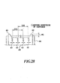
- an electric contact portion 23 having contacts 22 to receive driving signals for the printing head is provided on the upper portion of the side of the printing head 21.
- a carriage C has insertion portions for receiving the printing heads H (111, 112). These insertion portions have their respective electric contact portions 24, 25 with contact points 22A, respectively.
- the contact point 22A is responsible for transmitting a signal to the printing head H by contacting with the electric contact portion 23 on the head's side.
- the electric contact portions 24, 25 establish connection with a control system on a main body of the printing apparatus. As shown in Fig.
- the term "ink” herein used refers ink having a composition that includes an electrically conductive color material (e.g., carbon, ink dye) or an electrically conductive material (e.g., conductive fixing material, conductive liquid material).
- the term "the side" of a printing head refers at least one surface being laterally positioned in the direction of the respective movement of a carriage or a printing head with a cleaning member. That is, the side of the printing head is substantially parallel to the direction of the respective movement.
- a state of the ink deposit formed by the depositing of ink on the side of the printing head As a result, a width of the ink deposit from the orifice surface to the side was about 3 mm and a height of the ink deposit laterally protruding from the side was about 2.1 mm. Therefore, it is preferable that a structural component for removing the ink deposit is of about 3 mm or more in length and provided so as to face the side of the printing head. It is also preferable that such a structural component extends from the side to the opposite one with respect to the orifice surface. In addition, the distance from the side of the printing head to the structural component for removing the ink deposit depends on the amount of the ink deposit to be removed.
- the distance is theoretically in the range of 2 mm or less to allow the movement of the ink deposit from the side at a place facing to the side. In actuality, however, the distance may be in the range of 1 mm or less.
- a width of slit-cut described later is typically 0.5 mm but approximately 0.3 to 0.7 mm.
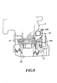
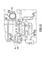
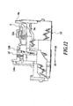
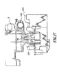
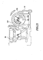
- Fig. 6, Fig. 7, and Fig. 8 are sectional views of a suction-pump portion, in which reference numeral 9 denotes an air-communicating tube, 10 denotes a suction tube, 11 denotes a suction pump, 12 denotes a recovery base, 13 denotes a suction roller, 14 denotes a roller holder, and 15 denotes a carriage lock.
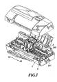
- the carriage 2 has a shaft bearing 100 through which a guide shaft 101 is passed so as to guide the movement of the carriage 2 reciprocally in the direction along the arrows A1 and A2 without restraint.
- the carriage lock 15 is constructed so as to be operated in conjunction with the suction pump 11 through a friction member 15a, so that it locks into place when the suction pump 11 rotates in the reverse direction (the arrow b) and it unlocks into place when the suction pump 11 rotates in the positive direction (the arrow a).
- the other end of the air-communicating tube 9 is inserted into the cap slider 8, and also a valve 17 is provided on its tip through a packing 17a.
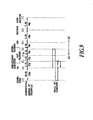
- the cap slider 8 slides over the valve 17 so as to open or close the valve 17 as a result of pushing the cap slider 8 with a motion of the carriage 2. That is, the valve 17 is in the closed state at the position [2] of Fig. 9, while it is in the opened state at the position [1]. Therefore, it becomes possible to perform a recovery operation at the position [2] where the printing head 1 is capped and the air-communicating tube 9 is closed. In the recovery operation, the suction pump 11 sucks up ink in the orifices of the printing head 1. It also becomes possible to perform a lost suction in which the suction pump 11 sucks up ink in the cap 6 at the position [1] where the printing head 1 is capped and the air-communicating tube 9 is opened.
- the head 111 is a photo head for ejecting magenta ink, cyan ink, and black ink in small concentrations and the head 112 is a color head for ejecting magenta ink, cyan ink, and yellow ink in high concentrations.
- a combination of these heads 111, 112 allows a print such as printing with six deferent color inks and provides a beautiful photographic print.
- Each of these heads 111, 112 may be provided as an inkjet cartridge by coupling with an ink tank.
- the photo head 111 may be displaced with a black head having an ink tank for black ink to allow a high speed text printing or a high speed business color print.
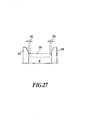
- the wiper 3 As shown in Fig. 18, there are four wiper slit portions 3a, 3b, 3c, and 3d.
- the slit 3a is formed on the position corresponding to the side 112a of the head 112
- the slit 3b is formed on the position corresponding to the side 111a of the head 111
- the slit 3c is formed on the position corresponding to the side 112b of the head 112
- the slit 3d is formed on the position corresponding to the side 111b of the head 111.
- the slit portions 3a, 3b, 3c, and 3d are formed on the positions facing to the sides 112a, 111a, 112b, and 111b, respectively.
- each of the slit portions 3a, 3b, 3c, and 3d is linearly formed along the predetermined area from a free end (the top) to a fixed end (the bottom) of the wiper 3 in the shape of a sheet.
- the side 111a of the printing head 111 is positioned on the side 21 of the head H in Fig. 29, i.e., the side of an electrically contact portion 23. It is noted that the scraper 26 is further provided so as to remove the ink deposit on that side 111a, so that it prevents the problems to be caused by a deposition of ink on the electric contact portion 23, such as the development of electric short circuit.
- Fig. 23 and Fig. 24 illustrate the third preferred embodiment of the present invention.
- Fig. 25 is a schematic representation of a main portion of a cleaning member in accordance with a fourth preferred embodiment of the present invention.
- the cleaning member of Fig. 25 has deep-grooved slits, so that there may be a warp in the wiper 30 at the time of cleaning the head H.
- the deposit-removing members 28, 29 are substantially free from such a warped wiper 30. Therefore, it is possible to keep the constant space (1 mm or less) between the deposit-removing members 28, 29 and the side of the head H, so that ink can be smoothly moved from the side thereof.
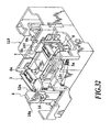
- An orifice surface of each of the heads 111, 112 is cleaned by a wiper 40 at first and then further cleaned by another wiper 44.
- the wiper 40 is positioned at the back side of the figure with respect to the deposit-removing members 41, 42.
- the wiper 44 is protruded over an end face of the wiper 40 to the head side as indicated by H1 in the figure to form a step between the wipers 40, 44, resulting in a more reliable cleaning of the orifice surface of the head.
- H1 can be defined in the range of plus 0.1 mm to minus 0.5 mm with respect to the height of the wiper 40. It would be better that the range of "H1" is defined so as to insure that the wiper 40 which is initially fall down by making contact with the head does not exert any influence upon the wiper 43.
- An alternative scraper may be prepared using an elastic material without integral with the cap holder 7 and placed in the same position as that of the first scraper 200 described above.
- the scraper 202 is ready for the printing head 112. However, it is not limited to such a configuration. It is also possible to provide a scraper 202 so as to be ready for more than one printing heads or all of the printing heads to be mounted on the printing apparatus together. It is also possible to provide scrapers on both sides of the printing head to simultaneously scrape ink deposits off.
- the present unclaimed example may be also applied on a printing apparatus having an additional head having the same configuration as those of the printing head 111 or 112 for ejecting a treatment liquid which is responsible for insolublizing or coagulating a color material in ink.
- An ink deposit on the side of a face (a surface on which orifices are formed for ejecting the treatment solution) may be scraped off by the scraper.
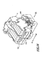
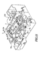
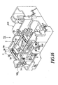
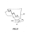
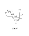
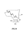
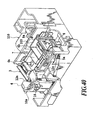
- Fig. 40 to Fig. 42 illustrate the third unclaimed example, in which a scraper 203 is arranged so as to be ready for a side portion located around a face 112A.
- the scraper 203 is configured so as to surround the all ride portions of the head 112, as shown in Fig. 40.
- the scraper 203 makes contact with the side of the head 112 and slides over to remove an ink deposit therefrom.
- the accumulation of viscous ink on the side of the printing head 112 can be prevented, so that an excellent print can be allowed all the time.
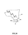
- the scraper 203 and the printing head 112 may shift their positions in a relative manner at the time of capping operation. It is also possible to shift the printing head 112 against the scraper 203. Therefore, the present unclaimed example does not limit the mechanism for the relative movement between the scraper 203 and the printing head 112, the direction of such a relative movement, and the like.
- the present invention achieves distinct effect when applied to a printing head or a printing apparatus which has means for generating thermal energy such as electrothermal transducers or laser light, and which causes changes in ink by the thermal energy so as to eject ink. This is because such a system can achieve a high density and high resolution printing.
- the number and type of printing heads to be mounted on a printing apparatus can be also changed. For example, only one printing head corresponding to a single color ink, or a plurality of printing heads corresponding to a plurality of inks different in color or concentration can be used.
- the present invention can be effectively applied to an apparatus having at least one of the monochromatic, multi-color and full-color modes.
- the monochromatic mode performs printing by using only one major color such as black.
- the multi-color mode carries out printing by using different color inks, and the full-color mode performs printing by color mixing.
- inks that are liquid when the printing signal is applied can be used: for example, inks can be employed that solidify at a temperature lower than the room temperature and are softened or liquefied in the room temperature. This is because in the ink jet system, the ink is generally temperature adjusted in a range of 30°C-70°C so that the viscosity of the ink is maintained at such a value that the ink can be ejected reliably.
- the present invention can be applied to such apparatus where the ink is liquefied just before the ejection by the thermal energy as follows so that the ink is expelled from the orifices in the liquid state, and then begins to solidify on hitting the printing medium, thereby preventing the ink evaporation: the ink is transformed from solid to liquid state by positively utilizing the thermal energy which would otherwise cause the temperature rise; or the ink, which is dry when left in air, is liquefied in response to the thermal energy of the printing signal.
- the ink may be retained in recesses or through holes formed in a porous sheet as liquid or solid substances so that the ink faces the electrothermal transducers as described in Japanese Patent Application Laying-open Nos. 54-56847 (1979) or 60-71260 (1985).
- the present invention is most effective when it uses the film boiling phenomenon to expel the ink.
- the ink jet printing apparatus of the present invention can be employed not only as an image output terminal of an information processing device such as a computer, but also as an output device of a copying machine including a reader, and as an output device of a facsimile apparatus having a transmission and receiving function.
Landscapes
- Ink Jet (AREA)
Claims (13)
- Druckgerät mit einem Reinigungsgerät, nachstehend als eine Reinigungsvorrichtung bezeichnet, zum Reinigen eines Tintenstrahldruckkopfs (1; 111; 112; H) mit einer Tintenausstoßfläche (1A), in welcher eine Vielzahl von Tintenausstoß-öffnungen zum Ausstoßen von Tinte erzeugt ist, in welchem die Tintenausstoßfläche (1A) durch eine Relativbewegung zwischen dem Druckkopf und der Reinigungsvorrichtung gereinigt wird, wobei die Reinigungsvorrichtung
dadurch gekennzeichnet ist, daß:ein Ablagerungsentfernelement (3; 28, 29; 34, 35; 37, 38; 41, 42; 200; 201; 202; 203) an einer Haltevorrichtung angeordnet ist und angepaßt ist, bei Verwendung in Gegenüberlage einer Seitenfläche des Druckkopfs, anders als die Tintenausstoßfläche (1A), zu sein, um in bezug auf diese zur Reinigung der Seitenfläche bewegbar zu sein, wobeisich die Seitenfläche des Druckkopfs im wesentlichen in der Richtung entlang der Relativbewegung zwischen dem Druckkopf und der Reinigungsvorrichtung erstreckt und angrenzend an und entlang einer Kante der Tintenausstoßfläche angeordnet ist, und wobeidas Ablagerungsentfernelement (3; 28, 29; 34, 35; 37, 38; 41, 42; 200; 201; 202; 203) angepaßt ist, den Kontakt mit der Seite des Druckkopfs (1; 111, 112; H) zu vermeiden und bei Verwendung den Kontakt mit einer Ablagerung auf der Seite des Druckkopfs herzustellen, um die Ablagerung von dieser zu entfernen. - Druckgerät gemäß Anspruch 1,
dadurch gekennzeichnet, daß:das Ablagerungsentfernelement (3; 28, 29; 34, 35; 37, 38; 41, 42; 200; 201; 202; 203) angepaßt ist, bei Verwendung zu der Seite des Druckkopfs (1; 111, 112; H) in einem Abstand von 1 mm oder weniger in Gegenüberlage angeordnet zusein. - Druckgerät gemäß Anspruch 1,
gekennzeichnet durch:eine Kappeneinheit (12, 6, 7), wobei das Ablagerungsentfernelement (3; 28, 29; 34, 35; 37, 38; 41, 42; 200; 201; 202; 203) an der Kappeneinheit (12, 6, 7) fest angeordnet gehalten wird, welche in bezug auf den Druckkopf (1; 111, 112; H) bewegbar ist. - Druckgerät gemäß Anspruch 1,
dadurch gekennzeichnet, daß:eine Vielzahl von Druckköpfen (111, 112) in dem Druckgerät angeordnet ist und das Ablagerungsentfernelement bei Verwendung zu Seiten der Vielzahl von Druckköpfen in Gegenüberlage ist. - Druckgerät gemäß Anspruch 4,
dadurch gekennzeichnet, daß:mindestens einer der Druckköpfe in einer Richtung versetzt ist, welche die Richtung der Relativbewegung zwischen dem Druckkopf und der Reinigungsvorrichtung kreuzt, wobei das Ablagerungsentfernelement (3; 28, 29; 34, 35; 37, 38; 41, 42; 200; 201; 202; 203) angepaßt ist, in Gegenüberlage der Seitenfläche von einem der Druckköpfe zu sein, mit einem anderen Abstand als der Rest der Druckköpfe. - Druckgerät gemäß Anspruch 3,
dadurch gekennzeichnet, daß:die Richtung der Relativbewegung zwischen dem Druckkopf und dem Ablagerungsentfernelement im wesentlichen in eine Hauptabtastbewegungsrichtung des Druckkopfs eingestellt ist. - Druckgerät gemäß Anspruch 3,
dadurch gekennzeichnet, daß:die Richtung der Relativbewegung zwischen dem Druckkopf und dem Ablagerungsentfernelement im wesentlichen in die Richtung eingestellt ist, welche die Hauptabtastbewegungsrichtung des Druckkopfs schneidet. - Druckgerät gemäß Anspruch 1,
dadurch gekennzeichnet, daß:der Druckkopf eine Vielzahl von Tintenausstoßöffnungen entlang einer Düsenreihe aufweist unddie Seite des Druckkopfs, zu welcher das Ablagerungsentfernelement angepaßt ist, bei Verwendung in Gegenüberlage zu sein, an einer Endseite der Düsenreihe angeordnet ist. - Druckgerät gemäß Anspruch 1,
dadurch gekennzeichnet, daß:der Druckkopf einen elektrischen Kontaktabschnitt aufweist unddie Seite des Druckkopfs, zu welcher das Ablagerungsentfernelement angepaßt ist, bei Verwendung in Gegenüberlage zu sein, auf der Seite des elektrischen Kontaktabschnitts angeordnet ist. - Druckgerät gemäß Anspruch 1, das ferner aufweist:ein elastisches Wischelement (3; 30; 33; 39; 40; 44) zum Wischen der Tintenausstoßfläche (1A) des Druckkopfs durch eine Relativbewegung zwischen dem elastischen Wischelement und dem Druckkopf, wobei
das elastische Wischelement in bezug auf das Ablagerungsentfernelement (3; 28, 29; 34, 35; 37, 38; 41, 42; 200; 201; 202; 203) verschiebbar ist. - Druckgerät gemäß Anspruch 10,
dadurch gekennzeichnet, daß:das elastische Wischelement (3; 30; 33; 39; 40; 44) und das Ablagerungsentfernelement (3; 28, 29; 34, 35; 37, 38; 41, 42; 200; 201; 202; 203) zu einem klingenförmigen elastischen Körper einstückig ausgebildet sind undein Schlitz (3a; 3b) in dem klingenförmigen elastischen Körper so erzeugt ist, daß der klingenförmige elastische Körper mit einem Abschnitt in Gegenüberlage der Seite des Druckkopfs versehen ist, und ein anderer Abschnitt als eine elastische Wischvorrichtung, die über die Tintenausstoßfläche des Druckkopfs gleitet. - Druckgerät gemäß Anspruch 10,
dadurch gekennzeichnet, daß:das Ablagerungsentfernelement (3; 28, 29; 34, 35; 37, 38; 41, 42; 200; 201; 202; 203) vor der Seite des Druckkopfs in einem vorbestimmten Abstand angeordnet ist und in der Lage ist, über mindestens einen Teil der Seite des Druckkopfs durch dessen Verschiebung als ein Ergebnis der Wischoperation der Tintenausstoßfläche des Druckkopfs mittels des elastischen Wischelements (3; 30; 33; 39; 40; 44) zu gleiten. - Druckgerät gemäß Anspruch 10,
dadurch gekennzeichnet, daß:die Richtung der Relativbewegung zwischen dem Ablagerungsentfernelement (200; 201; 202; 203) und dem Druckkopf von der Richtung der Relativbewegung zwischen dem elastischen Wischelement (3) und dem Druckkopf verschieden ist.
Applications Claiming Priority (6)
| Application Number | Priority Date | Filing Date | Title |
|---|---|---|---|
| JP14637098 | 1998-05-27 | ||
| JP14637098 | 1998-05-27 | ||
| JP25440998 | 1998-09-08 | ||
| JP25440998 | 1998-09-08 | ||
| JP31145398 | 1998-10-30 | ||
| JP31145398 | 1998-10-30 |
Publications (3)
| Publication Number | Publication Date |
|---|---|
| EP0960735A2 EP0960735A2 (de) | 1999-12-01 |
| EP0960735A3 EP0960735A3 (de) | 2000-04-26 |
| EP0960735B1 true EP0960735B1 (de) | 2003-07-30 |
Family
ID=27319165
Family Applications (1)
| Application Number | Title | Priority Date | Filing Date |
|---|---|---|---|
| EP19990110177 Expired - Lifetime EP0960735B1 (de) | 1998-05-27 | 1999-05-26 | Reinigungsgerät und Reinigungsverfahren für Tintenstrahldruckkopf |
Country Status (2)
| Country | Link |
|---|---|
| EP (1) | EP0960735B1 (de) |
| DE (1) | DE69909888T2 (de) |
Families Citing this family (2)
| Publication number | Priority date | Publication date | Assignee | Title |
|---|---|---|---|---|
| US6398340B1 (en) * | 2000-07-12 | 2002-06-04 | Acer Communications And Multimedia Inc. | Ink jet service station with a wiper moved by a wipe sled |
| US9409401B2 (en) | 2010-04-30 | 2016-08-09 | Hewlett-Packard Development Company, L.P. | Wiper for an inkjet printer |
Family Cites Families (12)
| Publication number | Priority date | Publication date | Assignee | Title |
|---|---|---|---|---|
| JPS62103147A (ja) * | 1985-10-31 | 1987-05-13 | Canon Inc | インクジエツト記録装置 |
| JPH0347754A (ja) * | 1989-04-26 | 1991-02-28 | Canon Inc | インクジェット記録装置 |
| JP2667277B2 (ja) * | 1990-03-14 | 1997-10-27 | キヤノン株式会社 | インクジェット記録装置 |
| US5644347A (en) * | 1992-09-21 | 1997-07-01 | Hewlett-Packard Company | Inkjet printer with variable wiping capabilities for multiple printheads |
| JPH06115065A (ja) * | 1992-10-09 | 1994-04-26 | Nec Corp | インクジェットプリンタ |
| JPH06134998A (ja) * | 1992-10-22 | 1994-05-17 | Canon Inc | インクジェット記録装置 |
| US5396271A (en) * | 1992-11-12 | 1995-03-07 | Xerox Corporation | Wiper blade cleaning system for non-coplanar nozzle faces of ink jet printheads |
| JPH07137270A (ja) * | 1993-11-16 | 1995-05-30 | Canon Inc | インクジェット記録装置 |
| JPH07171967A (ja) * | 1993-12-20 | 1995-07-11 | Canon Inc | インクジェット記録装置 |
| US5555461A (en) * | 1994-01-03 | 1996-09-10 | Xerox Corporation | Self cleaning wiper blade for cleaning nozzle faces of ink jet printheads |
| JPH07285226A (ja) * | 1994-04-19 | 1995-10-31 | Fuji Xerox Co Ltd | インクジェット記録装置 |
| US5548310A (en) * | 1994-10-17 | 1996-08-20 | Xerox Corporation | Automatic positioning of wiper blades in an ink jet printer maintenance station |
-
1999
- 1999-05-26 EP EP19990110177 patent/EP0960735B1/de not_active Expired - Lifetime
- 1999-05-26 DE DE69909888T patent/DE69909888T2/de not_active Expired - Lifetime
Also Published As
| Publication number | Publication date |
|---|---|
| EP0960735A2 (de) | 1999-12-01 |
| EP0960735A3 (de) | 2000-04-26 |
| DE69909888D1 (de) | 2003-09-04 |
| DE69909888T2 (de) | 2004-02-26 |
Similar Documents
| Publication | Publication Date | Title |
|---|---|---|
| US6702423B2 (en) | Cleaning device for inkjet printing head, cleaning method for inkjet printing head, inkjet recording apparatus, and wiper | |
| EP1350627B1 (de) | Reinigungsvorrichtung und Montageverfahren dafür zum Reinigen eines Tintenstrahldruckkopfes | |
| JP4366175B2 (ja) | インクジェット記録装置 | |
| JP2872431B2 (ja) | インクジェット記録装置 | |
| US6601943B2 (en) | Indexing scraper cleaning system for inkjet printheads | |
| EP0694400B1 (de) | Farbstrahldruckkopf, Farbstrahldruckkopfpatrone, Farbstrahlauszeichnungsapparat und Verfahren zum Herstellen des Kopfes | |
| US6189999B1 (en) | Multi-faceted wiper scraper system for inkjet printheads | |
| US6050671A (en) | Stalagmite dissolving spittoon system for inkjet printheads | |
| JP2002307698A (ja) | ヘッド吐出特性維持装置及びそれを備えたインクジェット式プリンタ | |
| US6637857B2 (en) | Ink jet recording apparatus and cleaning control method for wiping device in the apparatus | |
| US6644778B2 (en) | Stalagmite dissolving spittoon system for inkjet printheads | |
| EP0914953B1 (de) | Reinigungssystem elektrischer Kontakte für Tintenstrahlpatronen | |
| US6663218B2 (en) | Head recovery device, head recovery method and ink jet recording apparatus | |
| EP1075950A2 (de) | Tintenstrahlaufzeichnungsvorrichtung | |
| JP4217435B2 (ja) | インクジェット記録装置 | |
| US6247783B1 (en) | Storage and spittoon system for waste inkjet ink | |
| KR100522936B1 (ko) | 잉크젯 프린터의 메인트넌스 방법 | |
| US6517187B1 (en) | Method and apparatus for cleaning residual ink from printhead nozzle faces | |
| EP0960735B1 (de) | Reinigungsgerät und Reinigungsverfahren für Tintenstrahldruckkopf | |
| EP0913262A1 (de) | Reinigungsvorrichtung mit schmalen und breiten Wischblättern für Tintenstrahldruckköpfe | |
| US20230094421A1 (en) | Recording apparatus | |
| JP2000198211A (ja) | インクジェット記録ヘッド用クリ―ニング装置、インクジェット記録ヘッド用クリ―ニング方法、インクジェット記録装置、およびワイパ― | |
| US7625062B2 (en) | Inkjet image forming apparatus | |
| JPH10305587A (ja) | インクジェット記録装置 | |
| US6499824B1 (en) | Ink jet recording apparatus with dedicated wiping members |
Legal Events
| Date | Code | Title | Description |
|---|---|---|---|
| PUAI | Public reference made under article 153(3) epc to a published international application that has entered the european phase |
Free format text: ORIGINAL CODE: 0009012 |
|
| AK | Designated contracting states |
Kind code of ref document: A2 Designated state(s): DE ES FR GB IT NL |
|
| AX | Request for extension of the european patent |
Free format text: AL;LT;LV;MK;RO;SI |
|
| PUAL | Search report despatched |
Free format text: ORIGINAL CODE: 0009013 |
|
| AK | Designated contracting states |
Kind code of ref document: A3 Designated state(s): AT BE CH CY DE DK ES FI FR GB GR IE IT LI LU MC NL PT SE |
|
| AX | Request for extension of the european patent |
Free format text: AL;LT;LV;MK;RO;SI |
|
| RTI1 | Title (correction) |
Free format text: CLEANING DEVICE AND METHOD FOR INKJET PRINTING HEAD |
|
| 17P | Request for examination filed |
Effective date: 20000918 |
|
| 17Q | First examination report despatched |
Effective date: 20001117 |
|
| AKX | Designation fees paid |
Free format text: DE ES FR GB IT NL |
|
| GRAH | Despatch of communication of intention to grant a patent |
Free format text: ORIGINAL CODE: EPIDOS IGRA |
|
| GRAH | Despatch of communication of intention to grant a patent |
Free format text: ORIGINAL CODE: EPIDOS IGRA |
|
| GRAA | (expected) grant |
Free format text: ORIGINAL CODE: 0009210 |
|
| AK | Designated contracting states |
Designated state(s): DE ES FR GB IT NL |
|
| PG25 | Lapsed in a contracting state [announced via postgrant information from national office to epo] |
Ref country code: NL Free format text: LAPSE BECAUSE OF FAILURE TO SUBMIT A TRANSLATION OF THE DESCRIPTION OR TO PAY THE FEE WITHIN THE PRESCRIBED TIME-LIMIT Effective date: 20030730 |
|
| REG | Reference to a national code |
Ref country code: GB Ref legal event code: FG4D |
|
| REF | Corresponds to: |
Ref document number: 69909888 Country of ref document: DE Date of ref document: 20030904 Kind code of ref document: P |
|
| PG25 | Lapsed in a contracting state [announced via postgrant information from national office to epo] |
Ref country code: ES Free format text: LAPSE BECAUSE OF FAILURE TO SUBMIT A TRANSLATION OF THE DESCRIPTION OR TO PAY THE FEE WITHIN THE PRESCRIBED TIME-LIMIT Effective date: 20031110 |
|
| NLV1 | Nl: lapsed or annulled due to failure to fulfill the requirements of art. 29p and 29m of the patents act | ||
| ET | Fr: translation filed | ||
| PLBE | No opposition filed within time limit |
Free format text: ORIGINAL CODE: 0009261 |
|
| STAA | Information on the status of an ep patent application or granted ep patent |
Free format text: STATUS: NO OPPOSITION FILED WITHIN TIME LIMIT |
|
| 26N | No opposition filed |
Effective date: 20040504 |
|
| PGFP | Annual fee paid to national office [announced via postgrant information from national office to epo] |
Ref country code: IT Payment date: 20090514 Year of fee payment: 11 Ref country code: FR Payment date: 20090520 Year of fee payment: 11 |
|
| REG | Reference to a national code |
Ref country code: FR Ref legal event code: ST Effective date: 20110131 |
|
| PG25 | Lapsed in a contracting state [announced via postgrant information from national office to epo] |
Ref country code: IT Free format text: LAPSE BECAUSE OF NON-PAYMENT OF DUE FEES Effective date: 20100526 |
|
| PG25 | Lapsed in a contracting state [announced via postgrant information from national office to epo] |
Ref country code: FR Free format text: LAPSE BECAUSE OF NON-PAYMENT OF DUE FEES Effective date: 20100531 |
|
| PGFP | Annual fee paid to national office [announced via postgrant information from national office to epo] |
Ref country code: DE Payment date: 20150531 Year of fee payment: 17 Ref country code: GB Payment date: 20150528 Year of fee payment: 17 |
|
| REG | Reference to a national code |
Ref country code: DE Ref legal event code: R119 Ref document number: 69909888 Country of ref document: DE |
|
| GBPC | Gb: european patent ceased through non-payment of renewal fee |
Effective date: 20160526 |
|
| PG25 | Lapsed in a contracting state [announced via postgrant information from national office to epo] |
Ref country code: DE Free format text: LAPSE BECAUSE OF NON-PAYMENT OF DUE FEES Effective date: 20161201 |
|
| PG25 | Lapsed in a contracting state [announced via postgrant information from national office to epo] |
Ref country code: GB Free format text: LAPSE BECAUSE OF NON-PAYMENT OF DUE FEES Effective date: 20160526 |