EP0959532B1 - Steckverbinder mit Verriegelungshebel - Google Patents
Steckverbinder mit Verriegelungshebel Download PDFInfo
- Publication number
- EP0959532B1 EP0959532B1 EP99108696A EP99108696A EP0959532B1 EP 0959532 B1 EP0959532 B1 EP 0959532B1 EP 99108696 A EP99108696 A EP 99108696A EP 99108696 A EP99108696 A EP 99108696A EP 0959532 B1 EP0959532 B1 EP 0959532B1
- Authority
- EP
- European Patent Office
- Prior art keywords
- lever
- locking portion
- type connector
- connector
- lock claw
- Prior art date
- Legal status (The legal status is an assumption and is not a legal conclusion. Google has not performed a legal analysis and makes no representation as to the accuracy of the status listed.)
- Expired - Lifetime
Links
Images


Classifications
-
- H—ELECTRICITY
- H01—ELECTRIC ELEMENTS
- H01R—ELECTRICALLY-CONDUCTIVE CONNECTIONS; STRUCTURAL ASSOCIATIONS OF A PLURALITY OF MUTUALLY-INSULATED ELECTRICAL CONNECTING ELEMENTS; COUPLING DEVICES; CURRENT COLLECTORS
- H01R13/00—Details of coupling devices of the kinds covered by groups H01R12/70 or H01R24/00 - H01R33/00
- H01R13/62—Means for facilitating engagement or disengagement of coupling parts or for holding them in engagement
- H01R13/629—Additional means for facilitating engagement or disengagement of coupling parts, e.g. aligning or guiding means, levers, gas pressure electrical locking indicators, manufacturing tolerances
- H01R13/62933—Comprising exclusively pivoting lever
- H01R13/62955—Pivoting lever comprising supplementary/additional locking means
-
- H—ELECTRICITY
- H01—ELECTRIC ELEMENTS
- H01R—ELECTRICALLY-CONDUCTIVE CONNECTIONS; STRUCTURAL ASSOCIATIONS OF A PLURALITY OF MUTUALLY-INSULATED ELECTRICAL CONNECTING ELEMENTS; COUPLING DEVICES; CURRENT COLLECTORS
- H01R13/00—Details of coupling devices of the kinds covered by groups H01R12/70 or H01R24/00 - H01R33/00
- H01R13/46—Bases; Cases
- H01R13/52—Dustproof, splashproof, drip-proof, waterproof, or flameproof cases
- H01R13/5219—Sealing means between coupling parts, e.g. interfacial seal
-
- H—ELECTRICITY
- H01—ELECTRIC ELEMENTS
- H01R—ELECTRICALLY-CONDUCTIVE CONNECTIONS; STRUCTURAL ASSOCIATIONS OF A PLURALITY OF MUTUALLY-INSULATED ELECTRICAL CONNECTING ELEMENTS; COUPLING DEVICES; CURRENT COLLECTORS
- H01R13/00—Details of coupling devices of the kinds covered by groups H01R12/70 or H01R24/00 - H01R33/00
- H01R13/62—Means for facilitating engagement or disengagement of coupling parts or for holding them in engagement
- H01R13/629—Additional means for facilitating engagement or disengagement of coupling parts, e.g. aligning or guiding means, levers, gas pressure electrical locking indicators, manufacturing tolerances
- H01R13/62933—Comprising exclusively pivoting lever
- H01R13/62938—Pivoting lever comprising own camming means
Definitions
- the present invention relates to a lever type connector.
- FIGS. 13 and 14 show a lever type connector 100 disclosed in Japanese Unexamined Utility Model Publication No. 6-45275 .
- This connector 100 is provided with a lever 102 rotatably assembled therewith.
- a lock claw 105 engageable with a locking portion 104 provided on the top of a mating connector 103.
- the lever 102 When the lever type connector 100 is connected with the mating connector 103, the lever 102 is rotated to a position where it covers an upper part of the mating connector 103. By doing this, the lock claw 105 and the locking portion 104 are engaged to hold the lever 102 in a locking position (see FIG. 14).
- an unlocking portion 106 extending in a direction substantially opposite from the locking portion 104 is pressed to rotate the lever 102 in a direction opposite from the engaging direction while elastically deforming the locking portion 104 upward.
- the unlocking portion 106 With the lock claw 105 and the locking portion 104 engaged, the unlocking portion 106 is exposed. Thus, if an external force acts on the unlocking portion 106, there is an undesirable likelihood that the locking portion 104 and the lock claw 105 are mistakenly disengaged.
- EP 0 812 038 A2 discloses a locking apparatus for resin moulded product, wherein a facing face of a release member located at an anterior end of a resilient latching member is made parallel to a stopping face of a protrusion.
- the moulding of the stopping face is carried out by a moulded part whose mould opening direction is parallel to the stopping face and the facing face, thus obviating the need to leave a mould removing hole in the release member.
- EP 0 736 935 A2 discloses a lever type connector, in which a pair of housings are coupled to each other by operating a lever, said lever being selectively mounted on said housing in a reversible manner upon coupling between a pair of support axles and bearing holes.
- an object of the present invention is to provide a lever type connector in which the engagement by a lever is not inadvertently disengaged.
- a lever type connector comprising:
- the error disengagement restricting portion makes it difficult for this external force to directly act on the unlocking portion.
- an inadvertent disengagement of the lever and the locking portion can be restricted.
- the connector housing comprises a wire protection cover for protecting wires extending through the rear surface of the connector housing, the wire protection cover acting also as the error disengagement restricting portion.
- the wire protection cover acts also as the error disengagement restricting portion, it is not necessary to separately provide the error disengagement restricting portion.
- a recess in which the lock claw is arranged and a connection piece formed above the lock claw for connecting opening edges of the recess are provided preferably in a substantially middle portion of the lever, the connection piece being so formed as to restrict an excessive deformation of the lock claw in an unlocking direction.
- the leading end of the unlocking portion is so curved as to extend along a curved configuration of the outer surface of the wire protection cover while leaving a minimum interval or space (defined therebetween) necessary to effect unlocking when the lock claw and the locking portion are engaged with each other.
- the locking portion is provided on the wire protection cover. Accordingly, the locking of the lever can be securely performed, since the interaction between locking portion and lever is performed preferably at a distal portion of the lever.
- two locking portions are provided on opposite sides of the wire protection cover. Then, it is easily possible to safely connect the wire protection cover with a connector housing in a second position in which the cover and the housing are turned by 180° around their common longitudinal axis.
- the connector housing is provided with one or more locking portion protection portions preferably at its rear portion for protecting a front part of the locking portion. Accordingly, an external force is prevented from directly acting on the locking portion from front. Therefore, an undesirable event where the lock claw and the locking portion are inadvertently disengaged can be more securely avoided.
- the one or more locking portion protection portions are disposed in front of the locking portion and have a greater vertical dimension than the locking portion.
- the lever is rotatably or pivotably mounted on the connector housing by means of one or more lever mount portions, wherein the lever mount portions preferably comprise stopper portions for stopping a rotation of the lever in a predetermined or predeterminable position.
- cam elements are provided on the lever for the interaction of mating cam elements provided on the mating connector for forcibly mating the connectors upon rotating or pivoting the lever.
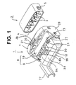
- FIG. 1 shows a state before a lever type connector 1 and a mating connector 2 are connected.
- sides of both connectors 1, 2 to be connected with each other are assumed to be front sides.
- Male terminal fittings 3 are accommodated in the mating connector 2 and substantially covered by a receptacle 4.
- a pair of cam pins 5 project at the opposite sides of the mating connector 2.
- the cam pins 5 are fitted into cam grooves 6 formed in a lever 7 of the lever type connector 1 preferably when the connectors 1, 2 are connected with each other.
- the mating connector 2 is substantially pulled into the level type connector 1 as the lever 7 is rotated, thereby being connected.
- the lever type connector 1 is made e.g. of a synthetic resin, and is provided with a connector housing 8 and the lever 7 rotatably or pivotably assembled with the connector housing 8.
- the connector housing 8 is comprised of a housing main body 19, and a wire protection cover 9 for substantially covering a rear part of the housing main body 19.
- the housing main body 19 is formed with cavities 11 for accommodating female terminal fittings 10 (see FIGS. 8 and 9).
- Two or more kinds of cavities 11 are preferably formed so as to be suited to the size of the female terminal fittings 10 to be accommodated therein.
- the cavities 11 are open at its front and rear ends.
- the rear ends of the cavities 11 are preferably widened to serve as terminal insertion openings 11A where the accommodation of the female terminal fittings 10 is started, whereas the front ends of the cavities 11 are preferably narrowed to serve as terminal connection openings B through which the male terminal fittings 3 are inserted.
- a locking portion 12 which is elastically engageable with the corresponding female terminal fitting 10.
- the female terminal fittings 10 accommodated or accommodatable in the cavities 11 are formed e.g. by bending conductive members and have a substantially box-shaped leading end into which the male terminal fitting 3 is insertable.
- a skirt portion 13 into which the receptacle 4 of the mating connector 2 is fittable projects.
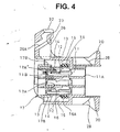
- a waterproof member 16 (FIG. 4) is fitted substantially entirely on the back of a wall portion 14.
- This waterproof member 16 is made e.g. of a synthetic rubber, and preferably three circumferentially extending projections 16A are formed on the outer surface thereof.
- the projections 16A are compressively deformed by the receptacle 4 of the mating connector 2 to hold connected portions of the connectors 1, 2 watertight.
- a retainer 17 is mounted or mountable preferably from the front of the wall portion 14.
- the retainer 17 has a slightly smaller outer diameter than the skirt portion 13 and is formed with an opening in a position substantially conforming to the positions of terminal connection openings B of the respective cavities 11.
- the retainer 17 is formed with deformation restricting portions 17A in positions corresponding to where the engaging portions 12 are elastically deformed when being brought into engagement with the female terminal fittings 10.
- An outer wall 17B of the retainer 17 engages the wall portion 14 in a position slightly forward than the leading edge of the waterproof member 16 (see FIGS. 8 and 9).
- the retainer 17 also has a function of preventing the waterproof member 16 from coming off.
- the retainer 17 and the waterproof member 16 form an engagement space 15 for substantially permitting the entry of the receptacle 4 of the mating connector 2.
- a pair of locking portion protection pieces 20 project or laterally or vertically stand preferably at the top and bottom portion of the rear end of the housing main body 19. These protection pieces 20 are located in front of locking portions 18 to be described later, and have a longer or greater vertical dimension (cross-sectional or frontal or transverse dimension) than the locking portions 18 to protect front parts of the locking portions 18.
- a pair of cover engaging portions 21 project on the left and right sides of each protection piece 20. The upper and lower cover engaging portions 21 are substantially symmetrically arranged, respectively and engaging portions 22 of the wire protection cover 9 are brought or bringable into engagement therewith.
- a pair of left and right lever mount portions 23 project from the skirt portion 13 of the housing main body 19.
- the lever mount portions 23 are substantially cylindrical, and the lever 7 is assembled so that the level mount portions 23 serve as a center of rotation or as pivotal center.
- a pair of stopper portions 23A project substantially along forward and backward directions.
- a pair of engagement slots 30 for permitting the insertion of the cam pins 5 of the mating connector 2 are formed in the left and right opening edges of the skirt portion 13.
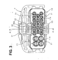
- the wire protection cover 9 is adapted to substantially orient wires W connected with the female terminal fittings 10 in a specified direction while at least partially covering a rear part of the housing main body 19.
- a covering portion 9A for substantially covering the rear part of the housing main body 19 is provided at the front part of the wire protection cover 9.
- At the leading end of the covering portion 9A are provided preferably four engaging portions 22 in positions conforming or corresponding to the cover engaging portions 21 provided on the housing main body 19.
- the engaging portions 22 are slightly elastically deformable along vertical direction, and substantially prevent the wire protection cover 9 from being disengaged from the housing main body 19 by their engagement with the cover engaging portions 22.
- Recesses 25 are formed preferably in substantially middle portions of the upper and lower parts of the covering portion 9A in order to avoid the locking portion protection pieces 20 of the housing main body 19.
- the locking portions 18 project at the rear edges of the recesses 25 (FIG. 6).
- One each of the locking portions 18 is formed on the upper and lower parts of the protection cover 9, and the lever 7 is engageable with either of them. In other words, the lever 7 can be mounted on a more suitable side, considering how the lever type connector 1 is to be used.
- a backward projecting claw 18A is formed at the leading end of each locking portion 18.
- In an upper portion of the claw 18A is formed a guide surface 18B for facilitating the engagement with a lock claw 26 of the lever 7 to be described later.
- a rear end surface of the wire protection cover 9 is so formed as to bulge out preferably backward, and this portion acts as an error disengagement preventing portion 28.
- a wire retaining portion 27 is provided at a lateral or left side of the rear part of the wire protection cover 9 in FIG. 1.
- the wire retaining portion 27 has a substantially U-shaped cross section as a gutter does.
- the wires W substantially covered by the covering portion 9A are substantially accommodated inside the wire retaining portion 27, and bundled by taping or clamping or by a covering element to substantially extend in a specified direction.
- the wire protection cover 9 is mountable on either the top or the bottom of the housing main body 19.
- the lever 7 is made e.g. of a synthetic resin to preferably have a substantially U-shape, and is so assembled as to locate the lateral or left and right surfaces of the connector housing 8 inside the end portions of the U-shaped lever 7.
- the lever 7 is rotatable or pivotal between a connection start position (position shown in FIG. 1) where the insertion of the cam pins 5 of the mating connector 2 is permitted and a connection end position (position shown in FIG. 2) where the connection of the connector 1 and the mating connector 2 is completed.
- a recess 31 is formed in a substantially middle portion of the lever 7.
- the lock claw 26 is provided inside the recess 31.
- the lock claw 26 is formed on a connecting piece for connecting the leading ends of a pair of elastic struts 26A extending obliquely backward from the outer surface of the recess 31.
- the elastic struts 26A are slightly vertically deformable, so that the lock claw 26 is elastically engageable with the locking portion 18 of the connector housing 8.
- the connecting piece for connecting the pair of elastic struts 26A is provided with an unlocking portion 33 in its portion more toward the leading end than the lock claw 26.
- the leading end of the unlocking portion 33 is so curved as to conform to a curved configuration of the outer surface of the error disengagement restricting portion 28 of the wire protection cover 9. Accordingly, when the lever 7 is rotated or pivoted to the connection end position, engaging the lock claw 26 and the locking portion 18 with each other, the unlocking portion 33 and the error disengagement restricting portion 28 are proximate or adjacent or neighbouring to each other while leaving only a minimum distance therebetween which is necessary to effect unlocking.
- the lever 7 is formed with a connection piece 32 for connecting an opening side of the recess 31. This connection piece 32 reinforces the strength of the recess 31 and prevents the lock claw 26 from being excessively elastically deformed upward.
- mount legs 29 At the opposite or lateral sides of the lever 7 are provided a pair of mount legs 29.
- the mount legs 29 are slightly elastically deformable in such a direction as to increase a distance therebetween.
- the cam grooves 6 are formed in the inner sides of the mount legs 29 (sides facing the connector housing 8).
- the cam pins 5 are guided along the cam grooves as the lever 7 is rotated or pivoted, thereby bringing or forcing the connectors 1, 2 closer to a position where they are connected.
- the respective mount legs 29 are formed with mount holes 24 (FIG. 5).
- mount holes 24 At the inner end of each mount hole 24 is formed a locking edge 24A projecting inward of the mount hole 24.
- the locking edges 24A are so shaped as to permit the passage of the lever mount portions 23 and hooks 23A of the housing main body.
- the locking edges 24A have a diameter slightly larger than the outer diameter of the lever mount portions 23, and is formed with notches for permitting the passage of the hooks 23A.
- the lever 7 and the connector housing 8 can be assembled only in a position where the lever mount portions 23 and the mount holes 24 are aligned. A position where the locking edges 24A permit the passage of the hooks 23A is attainable when the lever 7 is in the connection start position.
- FIG. 10 shows the lever type connector 1 when the lever 7 is substantially in the connection start position.
- the cam grooves 6 of the lever 7 are in alignment with or corresponding to the engagement slots 30 of the housing main body 19, thereby permitting the cam pins 5 of the mating connector 2 to be inserted.
- the cam pins 5 are substantially brought into contact with the edges of the cam grooves 6.
- the connectors 1, 2 are guided in such directions as to be connected with each other by rotating or pivoting the lever 7 from the connection start position to the connection end position (see FiG. 11).
- the lock claw 26 elastically moves over the claw 18A of the locking portion 18, the lock claw 26 and the locking portion 18 are engaged with each other, preventing the lever 7 from rotating in a reverse direction (or disengagement direction).
- the cam pins 5 reach preferably the very back of the engagement slots 30 by being pulled along the cam grooves 6, and the connection of the connectors 1, 2 is completed (see FIG. 12).
- the error disengagement restricting portion 28 is located on a side of the unlocking portion 33 where unlocking is effected.
- the error disengagement restricting portion 28 makes it difficult for the external force to directly act on the unlocking portion 33, preferably due to its outer shape substantially conforming that of the unlocking portion 33 (compare e.g. FIG. 12). Therefore, an inadvertent disengagement of the lever 7 and the locking portion 18 can be restricted.
- wire protection cover 9 preferably acts also as the error disengagement restricting portion 28, it is not necessary to separately provide the disengagement restricting portion 28.
- connection piece 32 (FIGS: 4, 9) strengthens the lever 7 by connecting the opening side of the recess 31 and prevents the excessive deformation of the lock claw 26. Therefore, it is not necessary to provided two separate members: the connection piece 32 and a member for preventing the excessive deformation.
- the leading end of the unlocking portion 33 is so curved as to conform to the curved configuration of the outer surface of the wire protection cover 9. This further improves a function of restricting the error disengagement of the lock claw 26 and the locking portion 18.
- the housing main body 19 is provided with the locking portion protection pieces 20, thereby preventing an external force from directly acting on the locking portion from front. Therefore, an undesirable event where the lock claw 26 and the locking portion 18 are inadvertently disengaged can be more securely avoided.
Landscapes
- Details Of Connecting Devices For Male And Female Coupling (AREA)
Claims (8)
- Steckverbinder mit Verriegelungshebel bzw. Hebeltyp-Verbinder (1), umfassend:ein Verbindergehäuse (8),einen Hebel (7), welcher drehbar oder schwenkbar an dem Verbindergehäuse (8) montiert bzw. angeordnet ist und mit wenigstens einer Verriegelungsklaue (26) versehen ist, welche elastisch mit wenigstens einem entsprechenden verriegelnden bzw. Verriegelungsabschnitt (18) in Eingriff bringbar ist, welcher an dem Verbindergehäuse (8) zur Verfügung gestellt bzw. vorgesehen ist, und einen entriegelnden bzw. Entriegelungsabschnitt (33) für ein Lösen bzw. Entkuppeln der Verriegelungsklaue (26) von dem verriegelnden Abschnitt (18) aufweist,wobei ein ein fehlerhaftes Lösen beschränkender Abschnitt bzw. Fehlerlöse-Beschränkungsabschnitt (28) benachbart einer Oberfläche bzw. Fläche des entriegelnden Abschnitts (33) zur Verfügung gestellt bzw. vorgesehen ist, wo ein Entriegeln bewirkt ist bzw. wird, wenn die Verriegelungsklaue (26) und der verriegelnde Abschnitt (18) miteinander in Eingriff gelangen (FIG. 12), um einen Raum zu verschmälern, welcher notwendig ist, um ein Entriegeln zu bewirken,wobei das Verbindergehäuse (8) eine Draht- bzw. Kabelschutzabdeckung (9) für ein Schützen von Drähten bzw. Kabeln (W) umfaßt, welche sich durch die rückwärtige Oberfläche bzw. Fläche des Verbindergehäuses (8) erstrecken, wobei der Hebeltyp-Verbinder (1) dadurch gekennzeichnet ist, daßder Drahtschutzabschnitt (9) auch als der Fehlerlöse-Beschränkungsabschnitt (28) wirkt, unddas vordere Ende des entriegelnden Abschnitts (33) so gekrümmt ist, um sich entlang einer gekrümmten Konfiguration der äußeren Oberfläche bzw. Fläche des Drahtschutzabschnitts (9) zu erstrecken, während ein minimales Intervall oder ein Raum frei bleibt, welches(r) dazwischen definiert ist, welches(r) notwendig ist, um ein Entriegeln zu bewirken, wenn die Verriegelungsklaue (26) und der Verriegelungsabschnitt (18) in Eingriff miteinander sind.
- Hebeltyp-Verbinder (1) nach Anspruch 1, wobei eine Vertiefung bzw. Aussparung bzw. ein Rücksprung (31), in welcher die Verriegelungsklaue (26) angeordnet ist, und ein Verbindungsstück (32), welches über der Verriegelungsklaue (26) für ein Verbinden von Öffnungsrändern bzw. -kanten der Vertiefung ausgebildet ist, vorzugsweise in einem im wesentlichen mittleren Abschnitt des Hebels (7) zur Verfügung gestellt bzw. vorgesehen sind, wobei das Verbindungsstück ausgebildet ist, um eine übermäßige Deformation der Verriegelungsklaue (26) in einer entriegelnden Richtung zu beschränken.
- Hebeltyp-Verbinder (1) nach Anspruch 1 oder 2, wobei der verriegelnde Abschnitt (18) an der Drahtschutzabdeckung (9) zur Verfügung gestellt bzw. vorgesehen ist.
- Hebeltyp-Verbinder (1) nach einem oder mehreren der vorangehenden Ansprüche, wobei das Verbindergehäuse (8) mit einem oder mehreren Verriegelungsabschnitt-Schutzabschnitt(en) (20) vorzugsweise an seinem rückwärtigen Abschnitt zum Schützen eines vorderen Teils des verriegelnden Abschnitts (18) versehen ist.
- Hebeltyp-Verbinder nach Anspruch 4, wobei der eine oder die mehreren Verriegelungsabschnitt-Schutzabschnitt(e) (20) vor dem verriegelnden Abschnitt (18) angeordnet ist bzw. sind und eine größere vertikale Abmessung als der verriegelnde Abschnitt (18) aufweist (aufweisen).
- Hebeltyp-Verbinder (1) nach einem oder mehreren der vorangehenden Ansprüche, wobei der Hebel (7) drehbar oder schwenkbar an dem Verbindergehäuse (8) mittels eines oder mehrerer Hebelmontageabschnitts(e) (23) montiert bzw. angeordnet ist, wobei die Hebelmontageabschnitte (23) vorzugsweise Anschlagabschnitte (23A) zum Stoppen bzw. Anschlag einer Rotation des Hebels (7) in einer vorbestimmten oder vorbestimmbaren Position umfassen.
- Hebeltyp-Verbinder (1) nach einem oder mehreren der vorangehenden Ansprüche, wobei Nockenelemente (6) an dem Hebel (7) für das Zusammenwirken von zusammenpassenden Nockenelementen (5), welche an dem zusammenpassenden Verbinder (2) zur Verfügung gestellt bzw. vorgesehen sind, für ein zwangsweises Zusammenpassen der Verbinder (1, 2) bei bzw. nach einem Rotieren oder Verschwenken des Hebels (7) zur Verfügung gestellt bzw. vorgesehen sind.
- Hebeltyp-Verbinder (1) nach einem oder mehreren der vorangehenden Ansprüche und Anspruch 3, wobei zwei verriegelnde Abschnitte (18) an gegenüberliegenden bzw. entgegengesetzten Seiten der Drahtschutzabdeckung (9) zur Verfügung gestellt sind.
Applications Claiming Priority (2)
| Application Number | Priority Date | Filing Date | Title |
|---|---|---|---|
| JP13965898 | 1998-05-21 | ||
| JP13965898A JP3252955B2 (ja) | 1998-05-21 | 1998-05-21 | レバー式コネクタ |
Publications (2)
| Publication Number | Publication Date |
|---|---|
| EP0959532A1 EP0959532A1 (de) | 1999-11-24 |
| EP0959532B1 true EP0959532B1 (de) | 2007-10-24 |
Family
ID=15250405
Family Applications (1)
| Application Number | Title | Priority Date | Filing Date |
|---|---|---|---|
| EP99108696A Expired - Lifetime EP0959532B1 (de) | 1998-05-21 | 1999-05-19 | Steckverbinder mit Verriegelungshebel |
Country Status (5)
| Country | Link |
|---|---|
| US (1) | US6241540B1 (de) |
| EP (1) | EP0959532B1 (de) |
| JP (1) | JP3252955B2 (de) |
| CN (1) | CN1132277C (de) |
| DE (1) | DE69937383T2 (de) |
Families Citing this family (27)
| Publication number | Priority date | Publication date | Assignee | Title |
|---|---|---|---|---|
| JP4156774B2 (ja) * | 2000-05-01 | 2008-09-24 | 住友電装株式会社 | レバー式コネクタ |
| JP3493628B2 (ja) * | 2001-01-18 | 2004-02-03 | 日本航空電子工業株式会社 | コネクタ装置 |
| FR2819944B1 (fr) * | 2001-01-23 | 2004-02-27 | Parker Hannifin Rak Sa | Dispositif de raccordement electrique embrochable |
| JP3911142B2 (ja) * | 2001-09-19 | 2007-05-09 | 矢崎総業株式会社 | レバー嵌合式コネクタ |
| JP3889627B2 (ja) * | 2002-01-16 | 2007-03-07 | Smk株式会社 | フレキシブル基板接続用コネクタ |
| US20040192090A1 (en) * | 2003-03-28 | 2004-09-30 | Flowers Robert J. | Lever type electrical connector with CPA member |
| US6827594B1 (en) * | 2003-06-23 | 2004-12-07 | Deere & Company | Connector assembly |
| JP4001113B2 (ja) * | 2004-01-14 | 2007-10-31 | 住友電装株式会社 | レバー式コネクタ |
| US7070438B2 (en) * | 2004-03-31 | 2006-07-04 | Jst Corporation | Connector lever lock |
| JP4229282B2 (ja) * | 2004-04-28 | 2009-02-25 | タイコエレクトロニクスアンプ株式会社 | レバー式コネクタ |
| CN100397724C (zh) * | 2005-01-12 | 2008-06-25 | 英业达股份有限公司 | 防止多功能扩充基座内的周边设备退出的锁具机构 |
| US7278867B1 (en) * | 2006-05-24 | 2007-10-09 | Super Micro Computer, Inc. | Displacement control device for an extractable power supply |
| JP4679458B2 (ja) * | 2006-07-19 | 2011-04-27 | モレックス インコーポレイテド | レバー付コネクタ |
| JP4857048B2 (ja) * | 2006-08-07 | 2012-01-18 | 日本航空電子工業株式会社 | レバー式コネクタ |
| DE602006013317D1 (de) * | 2006-09-21 | 2010-05-12 | Molex Inc | Hebelartiger elektrischer Steckverbinder |
| JP4985172B2 (ja) * | 2007-07-19 | 2012-07-25 | 住友電装株式会社 | レバー式コネクタ |
| JP4468465B2 (ja) * | 2008-03-28 | 2010-05-26 | タイコエレクトロニクスジャパン合同会社 | レバー式コネクタ |
| JP4387438B2 (ja) | 2008-03-28 | 2009-12-16 | タイコエレクトロニクスアンプ株式会社 | レバー式コネクタ |
| JP4405564B2 (ja) | 2008-04-21 | 2010-01-27 | タイコエレクトロニクスジャパン合同会社 | レバー式コネクタ |
| US8221153B2 (en) * | 2010-04-05 | 2012-07-17 | Anderson Power Products, Inc. | Tool-releasable solar power connector |
| CN102074840B (zh) * | 2010-11-24 | 2013-03-06 | 胡连精密股份有限公司 | 电连接器的锁定结构 |
| CN102480083B (zh) * | 2010-11-29 | 2014-05-14 | 胡连精密股份有限公司 | 一种电连接器的锁定结构及该电连接器 |
| JP5846105B2 (ja) * | 2012-11-13 | 2016-01-20 | 住友電装株式会社 | レバー式コネクタ |
| JP6190242B2 (ja) * | 2013-10-18 | 2017-08-30 | タイコエレクトロニクスジャパン合同会社 | レバー式コネクタ |
| JP2019117765A (ja) * | 2017-12-27 | 2019-07-18 | 第一精工株式会社 | レバー式コネクタ |
| CN108346935B (zh) * | 2018-03-02 | 2024-05-07 | 浙江正泰建筑电器有限公司 | 带自锁结构的插座 |
| JP2020149811A (ja) * | 2019-03-12 | 2020-09-17 | 住友電装株式会社 | レバー式コネクタ |
Family Cites Families (7)
| Publication number | Priority date | Publication date | Assignee | Title |
|---|---|---|---|---|
| JPH0645275A (ja) | 1991-06-21 | 1994-02-18 | Citizen Watch Co Ltd | 半導体装置の製造方法 |
| DE69308993T2 (de) | 1992-11-27 | 1997-11-06 | Sumitomo Wiring Systems | Handhebelbetätigter Verbinder |
| JP2817088B2 (ja) | 1994-02-23 | 1998-10-27 | 矢崎総業株式会社 | レバーロックの補強構造 |
| JP3516243B2 (ja) | 1994-11-30 | 2004-04-05 | 矢崎総業株式会社 | コネクタレバーのロック機構 |
| US5735702A (en) | 1995-04-07 | 1998-04-07 | Sumitomo Wiring Systems, Ltd. | Lever type connector |
| JP3206431B2 (ja) * | 1996-06-05 | 2001-09-10 | 住友電装株式会社 | 樹脂成形品のロック装置 |
| JP3275290B2 (ja) * | 1996-08-09 | 2002-04-15 | 住友電装株式会社 | レバー式コネクタ |
-
1998
- 1998-05-21 JP JP13965898A patent/JP3252955B2/ja not_active Expired - Fee Related
-
1999
- 1999-05-14 CN CN99107297.9A patent/CN1132277C/zh not_active Expired - Fee Related
- 1999-05-17 US US09/312,787 patent/US6241540B1/en not_active Expired - Lifetime
- 1999-05-19 DE DE69937383T patent/DE69937383T2/de not_active Expired - Lifetime
- 1999-05-19 EP EP99108696A patent/EP0959532B1/de not_active Expired - Lifetime
Also Published As
| Publication number | Publication date |
|---|---|
| JP3252955B2 (ja) | 2002-02-04 |
| DE69937383D1 (de) | 2007-12-06 |
| JPH11329582A (ja) | 1999-11-30 |
| EP0959532A1 (de) | 1999-11-24 |
| US6241540B1 (en) | 2001-06-05 |
| CN1132277C (zh) | 2003-12-24 |
| CN1237016A (zh) | 1999-12-01 |
| DE69937383T2 (de) | 2008-07-24 |
Similar Documents
| Publication | Publication Date | Title |
|---|---|---|
| EP0959532B1 (de) | Steckverbinder mit Verriegelungshebel | |
| KR100501561B1 (ko) | 전기 터미널용 카울 커넥터 | |
| US6364683B1 (en) | Electrical connector | |
| EP0818855B1 (de) | Verbinder | |
| JP3726641B2 (ja) | レバー式コネクタ | |
| US4220388A (en) | Electrical connector and contact and housing therefor | |
| US6439902B1 (en) | Pre-set locks for a connector lever | |
| EP1592091B1 (de) | Zwischenverbinder | |
| US5618207A (en) | Retaining method and double-retaining connector therefor | |
| US6375504B1 (en) | Connector and a cap therefor | |
| US6443760B2 (en) | Connector | |
| EP1005111A2 (de) | Verbinder | |
| EP0758806B1 (de) | Elektrischer Verbinder | |
| EP0848458B1 (de) | Verbinder mit Kupplungserkennungsmitteln | |
| EP1091451B1 (de) | Verbinder | |
| US6129574A (en) | Connector having a construction for preventing an erroneous assembling of a connector housing and a cover | |
| EP1801925B1 (de) | Verbinder und Verbinderanordnung | |
| EP1548894B1 (de) | Verbinder | |
| EP0963008A2 (de) | Ein Verbinder und eine Abdeckung dafür | |
| GB2349516A (en) | Contact-retaining shroud for electrical connector | |
| EP1528635B1 (de) | Modularer Verbinder, Zusammenbauverfahren und Verbindungsverfahren mit einem Gegenverbinder | |
| US5928014A (en) | Electrical connector having a pair of connector housings | |
| EP0427415B1 (de) | Wasserdichter Durchführungsverbinder für Kraftfahrzeuge | |
| JP3770050B2 (ja) | レバー式コネクタ | |
| EP0997986B1 (de) | Elektrischer Verbinder |
Legal Events
| Date | Code | Title | Description |
|---|---|---|---|
| PUAI | Public reference made under article 153(3) epc to a published international application that has entered the european phase |
Free format text: ORIGINAL CODE: 0009012 |
|
| 17P | Request for examination filed |
Effective date: 19990610 |
|
| AK | Designated contracting states |
Kind code of ref document: A1 Designated state(s): DE FR GB IT |
|
| AX | Request for extension of the european patent |
Free format text: AL;LT;LV;MK;RO;SI |
|
| AKX | Designation fees paid |
Free format text: DE FR GB IT |
|
| 17Q | First examination report despatched |
Effective date: 20041011 |
|
| GRAP | Despatch of communication of intention to grant a patent |
Free format text: ORIGINAL CODE: EPIDOSNIGR1 |
|
| RIN1 | Information on inventor provided before grant (corrected) |
Inventor name: TOKUWA, KOICHIRO |
|
| GRAS | Grant fee paid |
Free format text: ORIGINAL CODE: EPIDOSNIGR3 |
|
| GRAA | (expected) grant |
Free format text: ORIGINAL CODE: 0009210 |
|
| AK | Designated contracting states |
Kind code of ref document: B1 Designated state(s): DE FR GB IT |
|
| REG | Reference to a national code |
Ref country code: GB Ref legal event code: FG4D |
|
| REF | Corresponds to: |
Ref document number: 69937383 Country of ref document: DE Date of ref document: 20071206 Kind code of ref document: P |
|
| EN | Fr: translation not filed | ||
| PLBE | No opposition filed within time limit |
Free format text: ORIGINAL CODE: 0009261 |
|
| STAA | Information on the status of an ep patent application or granted ep patent |
Free format text: STATUS: NO OPPOSITION FILED WITHIN TIME LIMIT |
|
| 26N | No opposition filed |
Effective date: 20080725 |
|
| PG25 | Lapsed in a contracting state [announced via postgrant information from national office to epo] |
Ref country code: FR Free format text: LAPSE BECAUSE OF FAILURE TO SUBMIT A TRANSLATION OF THE DESCRIPTION OR TO PAY THE FEE WITHIN THE PRESCRIBED TIME-LIMIT Effective date: 20080808 |
|
| GBPC | Gb: european patent ceased through non-payment of renewal fee |
Effective date: 20080519 |
|
| PG25 | Lapsed in a contracting state [announced via postgrant information from national office to epo] |
Ref country code: GB Free format text: LAPSE BECAUSE OF NON-PAYMENT OF DUE FEES Effective date: 20080519 |
|
| PG25 | Lapsed in a contracting state [announced via postgrant information from national office to epo] |
Ref country code: IT Free format text: LAPSE BECAUSE OF NON-PAYMENT OF DUE FEES Effective date: 20080531 |
|
| PGFP | Annual fee paid to national office [announced via postgrant information from national office to epo] |
Ref country code: DE Payment date: 20120516 Year of fee payment: 14 |
|
| PG25 | Lapsed in a contracting state [announced via postgrant information from national office to epo] |
Ref country code: DE Free format text: LAPSE BECAUSE OF NON-PAYMENT OF DUE FEES Effective date: 20131203 |
|
| REG | Reference to a national code |
Ref country code: DE Ref legal event code: R119 Ref document number: 69937383 Country of ref document: DE Effective date: 20131203 |