EP0959472A1 - Bandkassette und Archivsystem mit optischer Übertragung zwischen Bandkassette und anderen Systemkomponenten - Google Patents
Bandkassette und Archivsystem mit optischer Übertragung zwischen Bandkassette und anderen Systemkomponenten Download PDFInfo
- Publication number
- EP0959472A1 EP0959472A1 EP98111745A EP98111745A EP0959472A1 EP 0959472 A1 EP0959472 A1 EP 0959472A1 EP 98111745 A EP98111745 A EP 98111745A EP 98111745 A EP98111745 A EP 98111745A EP 0959472 A1 EP0959472 A1 EP 0959472A1
- Authority
- EP
- European Patent Office
- Prior art keywords
- housing
- cassette
- tape
- data
- semiconductor memory
- Prior art date
- Legal status (The legal status is an assumption and is not a legal conclusion. Google has not performed a legal analysis and makes no representation as to the accuracy of the status listed.)
- Granted
Links
- 230000003287 optical effect Effects 0.000 title claims abstract description 75
- 238000004891 communication Methods 0.000 title description 2
- 239000004065 semiconductor Substances 0.000 claims abstract description 31
- 239000004020 conductor Substances 0.000 claims description 7
- 238000003780 insertion Methods 0.000 claims description 5
- 230000037431 insertion Effects 0.000 claims description 5
- 230000001419 dependent effect Effects 0.000 claims 1
- 230000013011 mating Effects 0.000 claims 1
- 239000002184 metal Substances 0.000 description 12
- 229910052751 metal Inorganic materials 0.000 description 12
- 238000000034 method Methods 0.000 description 11
- 238000013461 design Methods 0.000 description 10
- 230000005540 biological transmission Effects 0.000 description 8
- 238000010586 diagram Methods 0.000 description 6
- 238000004519 manufacturing process Methods 0.000 description 3
- 238000004140 cleaning Methods 0.000 description 2
- 230000006870 function Effects 0.000 description 2
- 239000000463 material Substances 0.000 description 2
- 238000012986 modification Methods 0.000 description 2
- 230000004048 modification Effects 0.000 description 2
- 230000008054 signal transmission Effects 0.000 description 2
- 238000013459 approach Methods 0.000 description 1
- 239000011248 coating agent Substances 0.000 description 1
- 238000000576 coating method Methods 0.000 description 1
- 230000001143 conditioned effect Effects 0.000 description 1
- 238000013144 data compression Methods 0.000 description 1
- 230000009977 dual effect Effects 0.000 description 1
- PCHJSUWPFVWCPO-UHFFFAOYSA-N gold Chemical compound [Au] PCHJSUWPFVWCPO-UHFFFAOYSA-N 0.000 description 1
- 239000010931 gold Substances 0.000 description 1
- 229910052737 gold Inorganic materials 0.000 description 1
- 230000001939 inductive effect Effects 0.000 description 1
- 239000003550 marker Substances 0.000 description 1
- 239000012811 non-conductive material Substances 0.000 description 1
- 230000008520 organization Effects 0.000 description 1
- 238000003860 storage Methods 0.000 description 1
- 238000012546 transfer Methods 0.000 description 1
- 238000012559 user support system Methods 0.000 description 1
- 230000003313 weakening effect Effects 0.000 description 1
Images


Classifications
-
- G—PHYSICS
- G11—INFORMATION STORAGE
- G11B—INFORMATION STORAGE BASED ON RELATIVE MOVEMENT BETWEEN RECORD CARRIER AND TRANSDUCER
- G11B23/00—Record carriers not specific to the method of recording or reproducing; Accessories, e.g. containers, specially adapted for co-operation with the recording or reproducing apparatus ; Intermediate mediums; Apparatus or processes specially adapted for their manufacture
- G11B23/02—Containers; Storing means both adapted to cooperate with the recording or reproducing means
- G11B23/04—Magazines; Cassettes for webs or filaments
- G11B23/08—Magazines; Cassettes for webs or filaments for housing webs or filaments having two distinct ends
- G11B23/087—Magazines; Cassettes for webs or filaments for housing webs or filaments having two distinct ends using two different reels or cores
- G11B23/08707—Details
- G11B23/08714—Auxiliary features
-
- G—PHYSICS
- G11—INFORMATION STORAGE
- G11B—INFORMATION STORAGE BASED ON RELATIVE MOVEMENT BETWEEN RECORD CARRIER AND TRANSDUCER
- G11B15/00—Driving, starting or stopping record carriers of filamentary or web form; Driving both such record carriers and heads; Guiding such record carriers or containers therefor; Control thereof; Control of operating function
- G11B15/675—Guiding containers, e.g. loading, ejecting cassettes
- G11B15/68—Automatic cassette changing arrangements; automatic tape changing arrangements
- G11B15/682—Automatic cassette changing arrangements; automatic tape changing arrangements with fixed magazines having fixed cassette storage cells, e.g. in racks
- G11B15/6835—Automatic cassette changing arrangements; automatic tape changing arrangements with fixed magazines having fixed cassette storage cells, e.g. in racks the cassettes being transferred to a fixed recorder or player using a moving carriage
-
- G—PHYSICS
- G11—INFORMATION STORAGE
- G11B—INFORMATION STORAGE BASED ON RELATIVE MOVEMENT BETWEEN RECORD CARRIER AND TRANSDUCER
- G11B27/00—Editing; Indexing; Addressing; Timing or synchronising; Monitoring; Measuring tape travel
- G11B27/002—Programmed access in sequence to a plurality of record carriers or indexed parts, e.g. tracks, thereof, e.g. for editing
-
- G—PHYSICS
- G11—INFORMATION STORAGE
- G11B—INFORMATION STORAGE BASED ON RELATIVE MOVEMENT BETWEEN RECORD CARRIER AND TRANSDUCER
- G11B27/00—Editing; Indexing; Addressing; Timing or synchronising; Monitoring; Measuring tape travel
- G11B27/10—Indexing; Addressing; Timing or synchronising; Measuring tape travel
- G11B27/11—Indexing; Addressing; Timing or synchronising; Measuring tape travel by using information not detectable on the record carrier
-
- G—PHYSICS
- G11—INFORMATION STORAGE
- G11B—INFORMATION STORAGE BASED ON RELATIVE MOVEMENT BETWEEN RECORD CARRIER AND TRANSDUCER
- G11B2220/00—Record carriers by type
- G11B2220/40—Combinations of multiple record carriers
- G11B2220/41—Flat as opposed to hierarchical combination, e.g. library of tapes or discs, CD changer, or groups of record carriers that together store one title
-
- G—PHYSICS
- G11—INFORMATION STORAGE
- G11B—INFORMATION STORAGE BASED ON RELATIVE MOVEMENT BETWEEN RECORD CARRIER AND TRANSDUCER
- G11B2220/00—Record carriers by type
- G11B2220/60—Solid state media
- G11B2220/65—Solid state media wherein solid state memory is used for storing indexing information or metadata
- G11B2220/652—Solid state media wherein solid state memory is used for storing indexing information or metadata said memory being attached to the recording medium
- G11B2220/655—Memory in cassette [MIC]
-
- G—PHYSICS
- G11—INFORMATION STORAGE
- G11B—INFORMATION STORAGE BASED ON RELATIVE MOVEMENT BETWEEN RECORD CARRIER AND TRANSDUCER
- G11B2220/00—Record carriers by type
- G11B2220/90—Tape-like record carriers
Definitions
- the present invention is directed to a tape cassette of the type containing a memory with data stored therein identifying characteristics of the cassette, the cassette being employed in a multi-cassette loader or library system, with the system communicating with the tape cassette to read and write information into and from the cassette memory.
- cassettes or cartridges can generally be categorized into three basic groups, these being the single reel cassette, the dual reel cassette, and the belt-driven cassette or cartridge.
- the tape drive and its connected computer system will organize the data on the tape in a defined manner, so that it can be read back at a later date even on another (compatible) system.
- a format organization includes some form of file structure (where related groups of data is organized in the same file or group of file names.).
- Older systems typically divide the various file groups by inserting special marker blocks (often named tape marks or file marks) between the file groups. Later, if a system knows that it wants the contents after a certain file mark, it can instruct the tape drive to quickly locate this particular file mark, and then read from there. This is one way to avoid having to read the tape sequentially to find the wanted data.
- Some modem tape systems go one step further by recording information about the file structure (name, contents and location on the tape) in a special section at the front end (beginning) of the tape. Therefore, the tape drive need only read this section to obtain information about the actual contents of the inserted tape. When this section is read, the tape drive can afterwards easily be instructed to go directly to a particular place on the tape and start reading (and maybe writing) from that point. This reduces the effective time to data and make the system operate more effectively.
- Figure 1 shows a simplified drawing of a conventional robotic system having a tape drive 100, a magazine 101 typically containing from 5 to 10 cartridges or cassettes 102 and a robot 103 which by command can pick a particular cartridge from the magazine and insert it into the drive or vice versa.
- An electronic controller unit 104 controls the operation of the robot. It get its information partly from the drive, partly from the robot and partly from the host system computer through a connected data and information bus 105.
- This bus 105 in addition to carrying the information and commands for the control of the robot, also contains data to either be recorded on the tape or extracted from the tape and sent to the computer.
- the robotic arm can pick up any one of the cassettes 102 and insert it into the tape drive 100.
- the drive 100 When the drive 100 has finished the read/write operations on the selected cassette 102 it will inform the electronic robot controller 104 which in turn will remove the cassette 102 from the drive 108 and insert it into an empty slot in the magazine 101. The host system will then instruct the robot to pick another cassette, etc.
- a loader like the one shown in Figure 1 will need to load a cassette and read at least the beginning of the tape to let the host find out whether it contains the wanted data. If it is not the correct one, the host must instruct the system to try the next cartridge and so on. Sometimes, if the cassette contains little or no data information recorded at the beginning of the tape, it may be necessary to read at least several sections of the tape to determine whether this contains the wanted data. This is a very time consuming and ineffective method.
- the robotic system of Figure 1 is a very primitive low end automatic system, normally called a "loader".
- a loader is very often used as the first step in automating a tape drive system.
- the user can set up the loader and the host to do automatic backup (for example during the night), without the need for any manual support. If the storage capacity on each cassette or cartridge is large enough, it can have a full day's backup on one cassette. In this case, the system can do automatic backup for a whole week without any user support.
- the system contains for example, 10 cassettes, it can even have a few spare cassettes in case something goes wrong with a cassette.
- One slot can also have a cleaning cassette for automatic cleaning operation when so required.
- Loaders like that shown in Figure 1 are becoming increasingly common as a low cost way to automate tape handling and backup. Larger systems, however, typically require better and more advanced tape automation. Such systems are normally called “libraries” , and are offered in many different forms. All libraries, however, contain at least two tape drives (many contain four or more drives) and various forms of magazines with cartridges/cassettes. Typically, a magazine may contain between 10 and 100 cassettes, and a library may have from one up to large numbers of magazines. All libraries also have one or more robots (robotic cassette pickers) which can pick any cassette from any of the magazines in the library and place it in any of the tape drives in the library.
- robots robot cassette pickers
- FIG. 2 shows a simplified block diagram of a library system having four drives 110, two magazines 111 with 10 cassettes 112, a robot cassette handler 113 controlled by an electronic controller unit 114.
- the commands to the electronic unit 114 come either from the host via a control bus 115 (very often combined so that it also carries data) or from the drives 110 or from the robot system 113 itself
- a control bus 115 very often combined so that it also carries data
- the drives 110 or from the robot system 113 itself
- the library is equipped with a bar code reader, such a reader is typically placed on the robot and the bar code information is fed to the electronic controller unit 114 and from there normally back to the host computer via the bus 115.
- a library system is very much the same as for the loader described in Figure 1, except that with more tape drives, the system can operate on more than one drive at a time. For example, one drive can wind or rewind the tape in one cassette, while another drive either read or write data from or to another cassette. Some systems can even read or write on more than one tape drive simultaneously. Therefore, a library system is more effective and can handle more data faster than a simple loader system.
- Some library systems are also designed so they can be interconnected with other library system in such a way that cassettes/cartridges can be fed from a magazine in one library to a magazine in another library. In this way, very large and sophisticated library systems can be built using small standard libraries as "building blocks".
- One method is to equip the library with its own memory containing information about the current contents of every cartridge/cassette in the library.
- a memory can be in the form of a (typically non-volatile) semiconductor memory like a flash memory or a D-RAM or S-RAM memory with battery backup, or it can be in the form of a hard disk.
- a special built-in memory systems can be very cost effective, and increase the throughput (time to wanted data) considerably, however, such a special memory system also increases the complexity and cost of the library and its operating software.
- the library memory system needs to go through a special update routine to learn the contents of the cassettes in the new magazine and remove the information about the contents in the old magazine. If several libraries are linked together, this special memory system must be updated every time a cassette is transferred from one library to the next one.
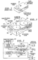
- FIG. 3 Another method fairly recently used is to equip each cassette or cartridge with its own non-volatile memory (typically, flash memory).
- flash memory typically, flash memory
- a memory chip 120 resides inside the cassette housing 121.
- the electrical control signals needed to write data into the memory chip or read data out of the chip, are supplied to the memory chip 120 via a set of electrical contacts 122 situated at the exterior of one side of the cassette housing.
- spring loaded electrical conducting fingers connect to the electrical contacts 122 so that the drive can write data to the chip 120 or read data from the chip 120.
- This method makes it possible to store a fairly large amount of information about the contents of a cassette in the memory chip of the same cassette.
- the drive can immediately read out the information without the need to begin running the tape to get information about the contents. Therefore, immediately after insertion, the drive can transfer information about the tape contents to the host. Compared with systems required to read special recorded information at the beginning of the tape, this system is much more effective. If the selected cassette does not contain the wanted information, the host can immediately instruct the robot and drive to remove the cassette and pick another one.
- This method is also very suitable when new data has been recorded to the tape, because the memory chip 120 can be updated in a very short time (normally less than 1 second) without the need to rewind the tape to the beginning and start recording cassette information at the beginning of the tape.
- the information about each cassette is always updated without having to go through a special update sequence (as is needed when the library contains for example a hard disk memory system).
- each cassette slot contains the necessary spring loaded contacts making connections to the memory chip inside each cassette.
- at least 5 to 7 contacts are required per cassette: two contacts for power connections, one serial data signal, one write enable signal and one read enable signal. Extra signals may be used to select special sections of the memory chip 120 etc.
- a method which has been proposed to overcome this, is to replace the connector system with a form of radio transmission system.
- Each cassette then contains a small radio transmitter and receiver.
- the idea is that each cassette can be selectively turned on by a coded radio signal sent out by a transmitter built into the library and will then transmit the contents of its memory chip to a receiver also situated in the library (or allowing new data to be written into the chip if so required).
- the power to the chip itself and the receiver/transmitter electronics inside each cassette has been proposed to come from the transmitted radio signal from the library.
- a small transformer picks up the transmitted radio signal from the library, rectifies it and uses this resulting DC power to power the built-in electronics in the cassette.
- the cassette magazines need not be modified at all.
- the transmitter serves two purposes. Its transmitted signal is picked up by the small transformer in each cassette, rectified and used to power the electronics in each cassette.
- the transmitted signal also contains coded information about which particular cassette the library system wants to address.
- the selected cassette turns on its transmitter, and transmit the data. The information is picked up by the receiver in the library and can then be sent back to the host.
- each cassette can probably be built with one integrated circuit and a few discrete components, it is still a fairly complex and expensive piece of electronics. For libraries having a large number of cassette, the cost of each cassette is very important.
- a third drawback is the problem of interference with other transmitted (radio) signals in the environment of the library. This could come from the use of mobile phones, TVs, radios, power supplies etc. Therefore, to ensure proper operation, such libraries need to be well protected against electrical interference.
- An object of the present invention is to provide a method and apparatus which allow for very simple read out of cassette data in a tape drive or a library without the problems mentioned above.
- This object is achieved in accordance with the invention by equipping a cassette having a non-volatile memory with an optical transmission reception capability to read out data from the memory or to write data to the memory. Circuits and designs similar to those used in handheld remote controllers for VCRs, TVs etc. can be used to keep the cost low.
- the inventive tape cassette or cartridge has a housing which, in addition to the conventional tape hub or hubs and the tape itself contains an electronic control circuit which controls the operation of a non-volatile memory chip in the housing, and also provides special control functions.
- the electronic control circuit contains or is connected to a transmitter circuit which is in turn connected to one or more light-emitting diodes so as to allow for optical transmission of information from the memory chip to an exterior location.
- the electronic control circuit is also connected to a receiver circuit which is in turn connected to an optical sensor, for receiving incoming optical signals for writing information into the memory chip.
- the electronic control unit also contains a cassette information memory, which contains a digital address which is unique to the cassette, and which may contain other unique cassette information, such as the date of manufacture, the name of the manufacturer, the cassette type, the tape (media) type and/or the tape length.
- cassette information memory which contains a digital address which is unique to the cassette, and which may contain other unique cassette information, such as the date of manufacture, the name of the manufacturer, the cassette type, the tape (media) type and/or the tape length.
- the optical sensor and the light-emitting diode or diodes are placed within the cassette housing so that they can easily receive and transmit data through the cassette housing to another component of a library system in which the cassette is employed.
- This other component may, for example, be a drive in which the cassette is contained, or a host computer of the library.
- the cassette can be provided with electrical contacts so that, when it is placed in an inventive magazine, it can be continuously powered so that the electronic control circuit therein is always "listening" for an interrogation of the cassette by the library.
- the robot can interrogate all cassettes within a magazine, or within a number of different magazines, in order to identify the cassette having the appropriate number or address associated with the wanted data.
- the cassette transmits an appropriate signal, so that the robot is then directed to remove that cassette from the magazine and place it in a drive.
- each cassette slot in the magazine contains such contacts, so that all cassettes in the magazine can be continuously supplied with power, so that all of the cassettes are always " listening" for an interrogation.
- the magazine is designed so that, under certain circumstances, each cassette may be individually supplied with power, rather than all cassettes being supplied with power in common. This can be useful if the library system does not "know" in advance the number or address of the cassette which contains the desired information. Sending out a signal from the library to all of the cassettes, asking them to transmit their address information, would result in all of the cassettes simultaneously transmitting signals back to the library. By having the capability of individually supplying power to only one cassette at a time, this allows an "unaddressed" signal to be transmitted from the library, but only the cassette which is currently receiving power will respond thereto.
- the "unaddressed" transmission contains an identification of the wanted data, and as the cassettes in the magazine are successively individually supplied with power, finally a match will occur between the data described in the transmitted signal and the data description stored in the memory of one of the cassettes, and this cassette will then respond to the library with an answer back signal.
- the basic components of a cassette constructed in accordance with the principles of the present invention are shown in Figure 4.
- the cassette has a housing 121 which contains one or more rotatable hubs 170, on which a magnetic tape 171 is wound. Data can be written onto and read from the magnetic tape 171 in a known manner.
- the structure of the housing 121 allowing for a read/write head to be brought into contact with the magnetic tape 171 can be of any form well-known to those of ordinary skill in the art, and is therefore not depicted in Figure 4.
- the housing 121 also contains an electronics unit 172 which, as explained in more detail in connection with Figure 5, is connected to an optical sensor 160 and an optical transmitter 161.
- the housing 121 can either be completely optically transparent, or can have sections thereof which are optically transparent, as described in more detail below, so as to allow optical signals to proceed to and from the optical sensor 160 and the optical transmitter 162.
- the electronics unit 172 contains an electronic control unit 153 which controls the operation of a non-volatile memory chip 154 and provides special control functions described later.
- the electronic control unit 153 contains an electronic read/write section 155 to either write data into the chip 154 or read it out of the chip 154.
- unit 153 also contains a receiver circuit 156 which can receive and decode optically coded signals received by an optical sensor 160.
- the optical sensor 160 can be in the form of an optically sensitive transistor or another optically designed sensitive receive unit.
- the electronic control unit 153 also contains a transmitter circuit 161 connected to one or more LEDs 162. Information in the form of coded visible or non-visible light can be received by the optical sensor 160 and sent to the receiver section 156. This receiver section 156 will decode the signal as described below.
- the electronic control unit 153 also contains a cassette information memory 157 which contains a digital unique address or number for each cassette. Furthermore, this memory 157 can contain other unique cassette information, such as date of manufacture, manufacturer's name, cassette type, tape (media) type and tape length.
- This unique address and cassette information contained in the memory 157 will normally be permanently programmed all during the manufacturing of the cassette.
- controller 163 (typically a microprocessor or a hardwired controller unit) which controls the total operation of the system. Control lines are connected to the various circuits inside the electronic control unit 153 and also to the non-volatile memory 154.
- two power connectors 158 and 159 are mounted on the cassette housing. These two connectors are described in more detail below.
- the optical sensor 160 and the LED 162 are placed so that they can easily receive and transmit data through the cassette housing to the outside drive or library.
- the cassette housing must Therefore be made in such a way that the optical signal can easily pass through (both ways).
- the cassette has been inserted in a suitable tape drive
- connectors in the drive supply power to the electronic control unit 153 through the two power connectors 158 and 159. If the drive transmits a suitable optical signal, it can be received by the optical sensor 160 and the receiver circuit 156.
- the optical signal will contain several information section or groups (blocks) of information data.
- One such group will contain the wanted cassette address (if the drive knows which cassette it wants).
- the control unit 153 will compare the wanted address number with its own contained in the memory 157. If there is a match, the electronic unit 153 will accept the command signal and react according to the other command or commands transmitted. If it is not a match, the cassette will just continue to "listen” or wait for new signal commands.
- the drive may either ask for data to be transmitted from the cassette's non-volatile memory 154 (or from the address/cassette information section 157) to the drive or vice versa.
- data is read out from the memory 154 (or 157) by the electronic read/write unit 155, sent to the transmitter 161 where it is properly coded and conditioned and is then sent to the LED 162 where it is transformed into an optical signal stream. This signal is then received by an optical receiving unit located in the drive.
- this system in principle is similar to those typically used in the receiver/transmitter system of a VCR or TV and its corresponding handheld remote control unit, and thus components for building such a system are very cheap. Normally, everything may be integrated into one or two chips with possibly only the LED 162 and/or the optical receiver 156 outside as separate (discrete) components.
- the operation to read out data will in principle be the same as when inserted in a tape drive. Power is supplied by two connectors in the magazine for each cassette. The cassette must be inserted so that the optical signal can pass between the cassette and the optical read/write unit in the library. This is discussed in more detail below.
- Power can either be selectively applied to each individual cassette, to all the cassettes in a magazine or to all magazines and cassettes in a whole library.
- Each of the powered cassettes will "listen" for the coded optical signal and look for its own unique cassette address. Every time a cassette detects its address it will execute according to the corresponding transmitted command (typically a read data command) and if so transmit the required data from its non-volatile memory as an optical signal stream to the receiver system located in the library. Since each cassette has a unique address, all cassettes can be powered continuously without fear of interference. Only the cassette being actually addressed will respond by sending data back to the library receiver. Furthermore, except for the cassette actually transmitting data, the power consumption for the other cassettes will typically be very low.
- each cassette may be powered separately if so required. This will make it possible for the library system to individually address each cassette and ask for its address number and other vital cassette data. Furthermore, this will also provide the library with information where each cassette is physically located (both for the magazine, if there is more than one magazine in the library, and also within each magazine). This again will allow the robot control system of the library to move the robot picking the cassettes more effectively and faster, since it knows precisely where each cassette is located.
- Figure 10 shows the basic principle for such a system allowing both selective (individual) powering for each cassette in a magazine containing (as an example) eight cassettes and for all the cassettes simultaneously.
- the base (0 volt) power signal is applied to all cassettes at all times.
- the three address lines A0, A1 and A2 from the library controller unit are decoded by a digital 3 to 8 decoder unit 180.
- a decoder override line B is also fed to the decoder unit 180.
- the override line B is set high, all the eight output lines E0 through E7 go to a high value, regardless of the value of the three address lines A0, A1 and A2.
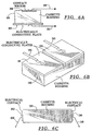
- FIGS 6A, 6B, 6C and 6D illustrate some examples.
- Figure 6A shows a cassette having a cassette housing 186 having a metal base plate 185.
- the drawing shows the cassette housing as seen from the side.
- the base plate 185 is used as one of the two power contacts.
- a gliding "finger spring" 187 in the drive or the magazine makes the necessary contact to the base plate 185. This may, for example, be the ground connection. From the base plate 185, a connection is made to the provide power to the electronic circuit inside the cassette.
- the other power connection is made to the top of the base plate, where a metal plate 188 is inserted.
- Another gliding "finger spring" 189 makes contact to this metal connector 188 and this may then, for example, be the positive voltage power connection.
- the position of the metal connector 188 and base plate 185 with respect to the fingers 187 and 189 is not very critical. Also, one or both of these fingers may be used to keep the cassette in place in a magazine (or in the drive), thereby serving two purposes at the same time.
- the metal connector 188 on the top cover of the cassette housing 186 in Figure 6A may be replaced by an area of conductive material or coating provided a suitable connection can be made between the spring finger 189 and the conductive area and between this area and the electronic control unit 153 inside the cassette.
- Figure 6B shows another variant wherein the base plate is formed of two metal plates 191 and 192 (or other suitable conductive material).
- Figure 6B shows the cassette from the bottom. Both plates 191 and 192 are contacted by spring fingers 194 and 193 in the drive and/or magazine, one finger at 0 volts power, the other at positive voltage power.
- the cassette housing 190 is made of a non-conductive material and keeps the two base plate elements 191 and 192 in place. Inside, the two base plates 191 and 192 are connected to the power connections for the electronic control unit 153.
- FIG. 6C Another variant shown in Figure 6C, has two metal plates or conductive areas 196 and 197 on two sides (preferably two parallel sides) of the cassette housing 195. Power is applied through two fingers 198 and 199 in the drive and/or magazine sliding along the metal plates 196 and 197.
- This design may be especially suitable for cassettes containing just one single tape reel. Such cassettes normally do not require a stiff metal base plate, and it may therefore be easier to have the connection on the sides.
- Figure 6D shows a design where two contacts 141 and 142 on the cassette housing 140 are small metal plates or connectors mounted side by side. (They may be placed either along one of the housing sides, or on the top or bottom of the housing). Springs in the drive and/or magazine again touch these two metal plates or connectors and carry the necessary currents. This design is especially suitable for cassettes having little space available for large area metal plate connectors.
- these spring loaded fingers used to connect electrical power to the cassette may do double duty as physical springs to keep the cassette stable in place, either inside the drive or inside the magazine.
- this may be quite important, as cassette which are not kept in place by some means of springs or equivalent, may physically be thrown out of the magazine when the magazine is moving (rotating) as is the case in many library systems. Therefore, typical magazines are designed with one or more "spring fingers" to keep each cassette in place and prevent that the cartridge accidentally falls out of the magazine during operation. Therefore, properly designed, the additional cost of having such springs to feed power may be negligible compared to a magazine not having this feature.
- the placement of the cassette inside the magazine is far less critical.
- the placement of the LED and optical sensor inside the cassette housing is critical in order to ensure the best possible transmission between the cassette and the transmitter/receiver system either when the cassette is loaded inside the tape drive or placed in a magazine in a library.
- the best placement is such that the optical signals pass through one of the (transparent) side walls of the cassette.
- Which side wall to use depends upon the actual cassette/cartridge design, and also the design of the drive itself and the magazines used in the library systems.
- the side through which the optical signals pass it should be the side wall facing away from the magazine as shown in Figure 7A.
- Figure 7A shows a magazine 120 with five cassettes 121.
- the LED transmitter and the optical sensor should be placed so that they easily can pick up the signals coming from or going to the cassette.
- the side wall projecting from a magazine as shown in Figure 7A may be the same side facing toward the drive cassette opening (sometimes covered by a flexible shield or door ) when the cassette is inserted into a drive as shown in Figure 7B.
- Figure 7B shows the tape drive 123, with the cassette 121 inserted in the tape drive 123 through the door opening 124, with the area 122 where the optical transmission signal (as shown in Figure 7A) may pass.
- the optical signal transmission 122 is an area on a cassette side not parallel and closest to the drive door when inserted in a drive.
- the signal transmission may pass through the area 122 which will also project outside the library magazine when the cassette is inserted in a magazine. Therefore, even when inserted in a magazine, the contents of the non-volatile memory may be transmitted to receiver/transmitter circuit placed in the library.
- the data contents stored in the non-volatile memory can be split in two parts as shown in Figure 9: a control section and a data information section. Not all cassettes or drives need to use all information in the control section, but by enabling such information to be recorded in the non-volatile memory, the performance level of the tape system may be further enhanced.
- control section should contain data bytes covering the following areas:
- the data section of the non-volatile memory should contain updated information about the data files recorded on the tape. This will allow a host system to quickly locate the cassette or cassettes containing the wanted data without even having to physically load the cassettes in a tape drive, and it will allow a tape drive to go to the wanted data in the most optimum, fastest way.
- Power can of course also be supplied to such an optical cassette system by using contactless inductive power and an integrated small transformer as previously mentioned, however, due to the complexity and cost of such a design and the risk of using magnetic power transmitters close to recorded tape media makes such design far less desirable.
- the optical data read/write system described here requires a much simpler and less critical mechanical connections; only ground and plus voltage power. While in the first case the connectors may need to be gold plated to ensure proper contacts even at very low signal levels, the optical read/write systems two mechanical contacts can be designed far simpler, more robust and with wider tolerances. Furthermore, as already mentioned, the spring contacts may be designed to do more than one job (both conducting current and keeping the cassette in a correct position) thereby reducing the total system cost even further.
- the cassette invention described here provides for more effective and less costly utilization of the cassette memory chip. especially when used in libraries as described earlier.
Landscapes
- Indexing, Searching, Synchronizing, And The Amount Of Synchronization Travel Of Record Carriers (AREA)
- Automatic Tape Cassette Changers (AREA)
Applications Claiming Priority (2)
| Application Number | Priority Date | Filing Date | Title |
|---|---|---|---|
| US83112 | 1998-05-22 | ||
| US09/083,112 US7123444B1 (en) | 1998-05-22 | 1998-05-22 | Tape cassette having an optical signal receiver and a memory for storing information optically transmitted into the cassette |
Publications (2)
| Publication Number | Publication Date |
|---|---|
| EP0959472A1 true EP0959472A1 (de) | 1999-11-24 |
| EP0959472B1 EP0959472B1 (de) | 2003-05-07 |
Family
ID=22176262
Family Applications (1)
| Application Number | Title | Priority Date | Filing Date |
|---|---|---|---|
| EP98111745A Expired - Lifetime EP0959472B1 (de) | 1998-05-22 | 1998-06-25 | Bandkassettenarchivsystem mit optischer Übertragung zwischen den Bandkassetten und anderen Systemkomponenten |
Country Status (3)
| Country | Link |
|---|---|
| US (1) | US7123444B1 (de) |
| EP (1) | EP0959472B1 (de) |
| DE (1) | DE69814355T2 (de) |
Cited By (4)
| Publication number | Priority date | Publication date | Assignee | Title |
|---|---|---|---|---|
| EP1041562A1 (de) * | 1998-09-21 | 2000-10-04 | Sony Corporation | Aufzeichnungsmediumsvorrichtung mit aufzeichnungsmedium und aufzeichnungs/ wiedergabevorrichtung |
| EP1523004A2 (de) * | 2003-10-09 | 2005-04-13 | Hewlett-Packard Development Company, L.P. | Datenträgerlagerungsanordnung und zugehöriges Betriebsverfahren |
| GB2410604A (en) * | 2004-01-30 | 2005-08-03 | Hewlett Packard Development Co | Storage library with cartridge identifiers and inventory |
| WO2008028810A1 (en) * | 2006-09-07 | 2008-03-13 | International Business Machines Corporation | Validation of the identity of a removable media volume mounted in an automated data storage library |
Families Citing this family (4)
| Publication number | Priority date | Publication date | Assignee | Title |
|---|---|---|---|---|
| JP4149886B2 (ja) * | 2003-09-18 | 2008-09-17 | 富士通株式会社 | ライブラリ装置 |
| US7359153B2 (en) * | 2004-07-28 | 2008-04-15 | Fujifilm Corporation | Recording medium cartridge |
| US20070253085A1 (en) * | 2006-04-28 | 2007-11-01 | Eric Soeken | Optically writing to and reading from housings of recordable data storage cartridges |
| US11915730B1 (en) * | 2023-06-13 | 2024-02-27 | International Business Machines Corporation | Magnetic media decommission management in a computer system |
Citations (8)
| Publication number | Priority date | Publication date | Assignee | Title |
|---|---|---|---|---|
| WO1989010615A1 (en) * | 1988-04-19 | 1989-11-02 | British Broadcasting Corporation | Cassette for sequential access recording medium and apparatus for use therewith |
| WO1993000680A1 (de) * | 1991-06-21 | 1993-01-07 | Siemens Nixdorf Informationssysteme Ag | Vorrichtung zum verfügbarmachen von den inhalt des massenspeichers eines maschinenlesbaren datenträgers beschreibenden und/oder ergänzenden daten |
| WO1993014501A1 (de) * | 1992-01-10 | 1993-07-22 | Deutsche Thomson-Brandt Gmbh | Kassette mit einem aufzeichnungsträger für ein aufzeichnungsgerät |
| WO1993016475A2 (de) * | 1992-02-14 | 1993-08-19 | Deutsche Thomson-Brandt Gmbh | Ständer mit fächern für aufzeichnungsträger enthaltende kassetten |
| WO1994002912A1 (de) * | 1992-07-23 | 1994-02-03 | Deutsche Thomson-Brandt Gmbh | Kontaktmittel, produkt mit diesem kontaktmittel und gerät zur aufnahme dieses produkts |
| EP0583904A2 (de) * | 1992-08-14 | 1994-02-23 | Sony Corporation | Aufzeichnungsträgerkassette, Anzeigegerät und Aufzeichnungs-Wiedergabegerät |
| WO1997029484A2 (en) * | 1996-02-09 | 1997-08-14 | Overland Data, Inc. | Automated tape cartridge library |
| WO1997045837A1 (en) * | 1996-05-30 | 1997-12-04 | Quantum Corporation | Magnetic tape cartridge system with cartridge status memory |
Family Cites Families (26)
| Publication number | Priority date | Publication date | Assignee | Title |
|---|---|---|---|---|
| BE871690R (fr) | 1978-10-27 | 1979-02-15 | Staar Sa | Dispositif de memorisation de la position instantanee d'une bande magnetique contenue dans une cassette |
| US4593337A (en) | 1983-03-16 | 1986-06-03 | Alfredo Leone | Video cassette play counting, storing and reading system |
| US5029034A (en) | 1985-04-19 | 1991-07-02 | Capital Cities/Abc Video Systems, Inc. | Video cassette with optical output of information |
| US4806960A (en) | 1988-01-11 | 1989-02-21 | Eastman Kodak Company | Cassette information controller and memory |
| US4806958A (en) * | 1988-01-11 | 1989-02-21 | Eastman Kodak Company | Cassette/machine optically coupled interface |
| US5023741A (en) | 1988-10-28 | 1991-06-11 | Polaroid Corporation | Programmable limited play video tape cassette |
| DK385489D0 (da) | 1989-08-07 | 1989-08-07 | Bang & Olufsen As | Optage- og gengivesystem, navnlig videosystem, med baandkassetter |
| EP0476445B1 (de) | 1990-09-17 | 1995-12-06 | Fuji Photo Film Co., Ltd. | Magnetbandkassette |
| DE4135371A1 (de) | 1991-10-26 | 1993-04-29 | Thomson Brandt Gmbh | Lesegeraet fuer einen statischen speicher einer kassette |
| US5434721A (en) | 1992-06-02 | 1995-07-18 | Sony Corporation | Recording/reproducing apparatus for recording/reproducing information to and/or from a plurality of types of recording medium cassettes |
| KR100262921B1 (ko) | 1992-10-22 | 2000-08-01 | 이데이 노부유끼 | 기록매체카셋트에기록된내용을보안하기위한장치와방법 |
| US5631784A (en) | 1992-11-13 | 1997-05-20 | Sony Corporation | Recording and reproducing apparatus and method of dubbing for record medium cassette |
| US5318370A (en) | 1992-11-17 | 1994-06-07 | Varitronic Systems, Inc. | Cartridge with data memory system and method regarding same |
| JP3764491B2 (ja) | 1992-12-21 | 2006-04-05 | ソニー株式会社 | Vtr |
| CA2112419C (en) | 1992-12-28 | 2004-04-06 | Ken Iizuka | Tape cassette including memory unit storing reproduction control instructions |
| US5521802A (en) | 1993-01-15 | 1996-05-28 | Edington; Daniel C. | Light enhanced music labels |
| TW230252B (en) | 1993-03-17 | 1994-09-11 | Sony Co Ltd | A cassette having a recording medium and a recording/reproducing apparatus for use with the cassette |
| MY117752A (en) | 1993-04-14 | 2004-08-30 | Victor Company Of Japan | Tape cassette mounted with ic memory package and ic connecting system for the tape cassette. |
| DE69422843T2 (de) | 1993-04-20 | 2000-10-26 | Matsushita Electric Ind Co Ltd | Aufzeichnungsvorrichtung |
| US5455409A (en) | 1993-08-16 | 1995-10-03 | Texas Digital Systems, Inc. | Apparatus and method for monitoring a plurality of coded articles and for identifying the location of selected articles |
| JP3339123B2 (ja) | 1993-08-24 | 2002-10-28 | ソニー株式会社 | 録画情報記録方法 |
| US6101070A (en) | 1993-09-30 | 2000-08-08 | Sony Corporation | Method and apparatus for determining information and a cassette for use therewith |
| ATE203624T1 (de) | 1993-09-30 | 2001-08-15 | Sony Corp | Kassetten mit speichern |
| US5511891A (en) | 1994-06-14 | 1996-04-30 | Varitronic Systems, Inc. | Tape printing machine with IR sensing |
| US5638228A (en) | 1995-02-14 | 1997-06-10 | Iomega Corporation | Retroreflective marker for data storage cartridge |
| BE1009562A3 (fr) | 1995-09-01 | 1997-05-06 | Staar Sa | Dispositif de lecture d'informations contenues dans le circuit memoire d'une cassette. |
-
1998
- 1998-05-22 US US09/083,112 patent/US7123444B1/en not_active Expired - Lifetime
- 1998-06-25 EP EP98111745A patent/EP0959472B1/de not_active Expired - Lifetime
- 1998-06-25 DE DE69814355T patent/DE69814355T2/de not_active Expired - Fee Related
Patent Citations (8)
| Publication number | Priority date | Publication date | Assignee | Title |
|---|---|---|---|---|
| WO1989010615A1 (en) * | 1988-04-19 | 1989-11-02 | British Broadcasting Corporation | Cassette for sequential access recording medium and apparatus for use therewith |
| WO1993000680A1 (de) * | 1991-06-21 | 1993-01-07 | Siemens Nixdorf Informationssysteme Ag | Vorrichtung zum verfügbarmachen von den inhalt des massenspeichers eines maschinenlesbaren datenträgers beschreibenden und/oder ergänzenden daten |
| WO1993014501A1 (de) * | 1992-01-10 | 1993-07-22 | Deutsche Thomson-Brandt Gmbh | Kassette mit einem aufzeichnungsträger für ein aufzeichnungsgerät |
| WO1993016475A2 (de) * | 1992-02-14 | 1993-08-19 | Deutsche Thomson-Brandt Gmbh | Ständer mit fächern für aufzeichnungsträger enthaltende kassetten |
| WO1994002912A1 (de) * | 1992-07-23 | 1994-02-03 | Deutsche Thomson-Brandt Gmbh | Kontaktmittel, produkt mit diesem kontaktmittel und gerät zur aufnahme dieses produkts |
| EP0583904A2 (de) * | 1992-08-14 | 1994-02-23 | Sony Corporation | Aufzeichnungsträgerkassette, Anzeigegerät und Aufzeichnungs-Wiedergabegerät |
| WO1997029484A2 (en) * | 1996-02-09 | 1997-08-14 | Overland Data, Inc. | Automated tape cartridge library |
| WO1997045837A1 (en) * | 1996-05-30 | 1997-12-04 | Quantum Corporation | Magnetic tape cartridge system with cartridge status memory |
Cited By (8)
| Publication number | Priority date | Publication date | Assignee | Title |
|---|---|---|---|---|
| EP1041562A1 (de) * | 1998-09-21 | 2000-10-04 | Sony Corporation | Aufzeichnungsmediumsvorrichtung mit aufzeichnungsmedium und aufzeichnungs/ wiedergabevorrichtung |
| EP1041562A4 (de) * | 1998-09-21 | 2001-01-10 | Sony Corp | Aufzeichnungsmediumsvorrichtung mit aufzeichnungsmedium und aufzeichnungs/ wiedergabevorrichtung |
| US6680817B1 (en) | 1998-09-21 | 2004-01-20 | Sony Corporation | Recording medium device containing recording medium and recording/reproducing device |
| EP1523004A2 (de) * | 2003-10-09 | 2005-04-13 | Hewlett-Packard Development Company, L.P. | Datenträgerlagerungsanordnung und zugehöriges Betriebsverfahren |
| GB2406960A (en) * | 2003-10-09 | 2005-04-13 | Hewlett Packard Development Co | A data storage library for media cartridges with memories |
| EP1523004A3 (de) * | 2003-10-09 | 2006-02-08 | Hewlett-Packard Development Company, L.P. | Datenträgerlagerungsanordnung und zugehöriges Betriebsverfahren |
| GB2410604A (en) * | 2004-01-30 | 2005-08-03 | Hewlett Packard Development Co | Storage library with cartridge identifiers and inventory |
| WO2008028810A1 (en) * | 2006-09-07 | 2008-03-13 | International Business Machines Corporation | Validation of the identity of a removable media volume mounted in an automated data storage library |
Also Published As
| Publication number | Publication date |
|---|---|
| DE69814355D1 (de) | 2003-06-12 |
| DE69814355T2 (de) | 2004-03-25 |
| US7123444B1 (en) | 2006-10-17 |
| EP0959472B1 (de) | 2003-05-07 |
Similar Documents
| Publication | Publication Date | Title |
|---|---|---|
| EP1239479B1 (de) | Vorrichtung und Verfahren zum Wiederauffinden von Daten aus einer Informationskassette | |
| US6195007B1 (en) | Recording medium handling apparatus | |
| EP0230642B1 (de) | Werkzeugidentifikationssystem | |
| JP4421333B2 (ja) | フレキシブル回路要素を用いて性能を高めたアンテナ | |
| EP0978841A2 (de) | Verfahren und Gerät zur Steuerung eines Aufzeichnungsmediums | |
| EP1225577B1 (de) | Vorrichtung und Verfahren zum Wiederauffinden von Daten , eine Datencassette betreffend | |
| US5455409A (en) | Apparatus and method for monitoring a plurality of coded articles and for identifying the location of selected articles | |
| US7116229B1 (en) | Programming a remote control device using RFID technology | |
| EP0944085A2 (de) | Zweiachsiges Leseverfahren für einen Speicherchip auf eine Kassette | |
| US7123444B1 (en) | Tape cassette having an optical signal receiver and a memory for storing information optically transmitted into the cassette | |
| JPH06124531A (ja) | マガジン制御を有するスタッカー/オートローダー装置 | |
| US7382990B2 (en) | Image forming apparatus | |
| US6970317B2 (en) | Recording medium control method and recording medium adapter | |
| KR20040029953A (ko) | 기록매체의 메모리와 통신을 행하는 통신장치 및 기록매체드라이브 장치 | |
| US20030067702A1 (en) | Display on cartridge for storage medium | |
| EP1315160A1 (de) | Vorrichtung und Verfahren zum Wiederauffinden von Daten | |
| GB2185134A (en) | Memory package | |
| US20050083796A1 (en) | Storage structure and associated method | |
| WO1997045837A1 (en) | Magnetic tape cartridge system with cartridge status memory | |
| JP2002189994A (ja) | 非接触式半導体メモリに対する通信装置、テープドライブ装置、ライブラリ装置、オートローダー装置、リーダー装置 | |
| US20020114096A1 (en) | Apparatus and method for retrieving data cartridge information in a cartridge receiving device | |
| US7212118B1 (en) | Pluggable cartridge memory chip and memory access | |
| US20070019318A1 (en) | Data transfer apparatus and method for transferring data | |
| JP2006246024A (ja) | カメラ一体型vtrにおけるユーザインターフェース | |
| JP2004146553A (ja) | 部品供給カセット、部品実装装置、及び、部品実装システム |
Legal Events
| Date | Code | Title | Description |
|---|---|---|---|
| PUAI | Public reference made under article 153(3) epc to a published international application that has entered the european phase |
Free format text: ORIGINAL CODE: 0009012 |
|
| AK | Designated contracting states |
Kind code of ref document: A1 Designated state(s): DE GB |
|
| AX | Request for extension of the european patent |
Free format text: AL;LT;LV;MK;RO;SI |
|
| 17P | Request for examination filed |
Effective date: 20000515 |
|
| AKX | Designation fees paid |
Free format text: DE GB |
|
| 17Q | First examination report despatched |
Effective date: 20000717 |
|
| GRAH | Despatch of communication of intention to grant a patent |
Free format text: ORIGINAL CODE: EPIDOS IGRA |
|
| RTI1 | Title (correction) |
Free format text: TAPE CASSETTE LIBRARY SYSTEM WITH OPTICAL COMMUNICATION BETWEEN THE TAPE CASSETTES AND OTHER SYSTEM COMPONENTS |
|
| GRAH | Despatch of communication of intention to grant a patent |
Free format text: ORIGINAL CODE: EPIDOS IGRA |
|
| GRAA | (expected) grant |
Free format text: ORIGINAL CODE: 0009210 |
|
| AK | Designated contracting states |
Designated state(s): DE GB |
|
| REG | Reference to a national code |
Ref country code: GB Ref legal event code: FG4D |
|
| REF | Corresponds to: |
Ref document number: 69814355 Country of ref document: DE Date of ref document: 20030612 Kind code of ref document: P |
|
| PLBE | No opposition filed within time limit |
Free format text: ORIGINAL CODE: 0009261 |
|
| STAA | Information on the status of an ep patent application or granted ep patent |
Free format text: STATUS: NO OPPOSITION FILED WITHIN TIME LIMIT |
|
| 26N | No opposition filed |
Effective date: 20040210 |
|
| PGFP | Annual fee paid to national office [announced via postgrant information from national office to epo] |
Ref country code: DE Payment date: 20070608 Year of fee payment: 10 |
|
| PGFP | Annual fee paid to national office [announced via postgrant information from national office to epo] |
Ref country code: GB Payment date: 20070620 Year of fee payment: 10 |
|
| GBPC | Gb: european patent ceased through non-payment of renewal fee |
Effective date: 20080625 |
|
| PG25 | Lapsed in a contracting state [announced via postgrant information from national office to epo] |
Ref country code: DE Free format text: LAPSE BECAUSE OF NON-PAYMENT OF DUE FEES Effective date: 20090101 |
|
| PG25 | Lapsed in a contracting state [announced via postgrant information from national office to epo] |
Ref country code: GB Free format text: LAPSE BECAUSE OF NON-PAYMENT OF DUE FEES Effective date: 20080625 |