EP0959216B1 - Anordnung zur hydraulischen Betätigung eines Heckdeckels - Google Patents
Anordnung zur hydraulischen Betätigung eines Heckdeckels Download PDFInfo
- Publication number
- EP0959216B1 EP0959216B1 EP99890103A EP99890103A EP0959216B1 EP 0959216 B1 EP0959216 B1 EP 0959216B1 EP 99890103 A EP99890103 A EP 99890103A EP 99890103 A EP99890103 A EP 99890103A EP 0959216 B1 EP0959216 B1 EP 0959216B1
- Authority
- EP
- European Patent Office
- Prior art keywords
- check valve
- hydraulic
- working
- working chamber
- cover flap
- Prior art date
- Legal status (The legal status is an assumption and is not a legal conclusion. Google has not performed a legal analysis and makes no representation as to the accuracy of the status listed.)
- Expired - Lifetime
Links
- 230000009977 dual effect Effects 0.000 claims 1
- 101001017827 Mus musculus Leucine-rich repeat flightless-interacting protein 1 Proteins 0.000 description 12
- 239000012530 fluid Substances 0.000 description 3
- 230000036316 preload Effects 0.000 description 3
- 230000006378 damage Effects 0.000 description 2
- 238000012423 maintenance Methods 0.000 description 2
- 238000010943 off-gassing Methods 0.000 description 2
- 208000027418 Wounds and injury Diseases 0.000 description 1
- 230000004308 accommodation Effects 0.000 description 1
- 238000010586 diagram Methods 0.000 description 1
- 208000014674 injury Diseases 0.000 description 1
- 210000003660 reticulum Anatomy 0.000 description 1
- 230000008093 supporting effect Effects 0.000 description 1
- 230000003319 supportive effect Effects 0.000 description 1
- 238000009423 ventilation Methods 0.000 description 1
Images
Classifications
-
- F—MECHANICAL ENGINEERING; LIGHTING; HEATING; WEAPONS; BLASTING
- F15—FLUID-PRESSURE ACTUATORS; HYDRAULICS OR PNEUMATICS IN GENERAL
- F15B—SYSTEMS ACTING BY MEANS OF FLUIDS IN GENERAL; FLUID-PRESSURE ACTUATORS, e.g. SERVOMOTORS; DETAILS OF FLUID-PRESSURE SYSTEMS, NOT OTHERWISE PROVIDED FOR
- F15B7/00—Systems in which the movement produced is definitely related to the output of a volumetric pump; Telemotors
- F15B7/005—With rotary or crank input
- F15B7/006—Rotary pump input
-
- F—MECHANICAL ENGINEERING; LIGHTING; HEATING; WEAPONS; BLASTING
- F15—FLUID-PRESSURE ACTUATORS; HYDRAULICS OR PNEUMATICS IN GENERAL
- F15B—SYSTEMS ACTING BY MEANS OF FLUIDS IN GENERAL; FLUID-PRESSURE ACTUATORS, e.g. SERVOMOTORS; DETAILS OF FLUID-PRESSURE SYSTEMS, NOT OTHERWISE PROVIDED FOR
- F15B11/00—Servomotor systems without provision for follow-up action; Circuits therefor
- F15B11/003—Systems with load-holding valves
-
- F—MECHANICAL ENGINEERING; LIGHTING; HEATING; WEAPONS; BLASTING
- F15—FLUID-PRESSURE ACTUATORS; HYDRAULICS OR PNEUMATICS IN GENERAL
- F15B—SYSTEMS ACTING BY MEANS OF FLUIDS IN GENERAL; FLUID-PRESSURE ACTUATORS, e.g. SERVOMOTORS; DETAILS OF FLUID-PRESSURE SYSTEMS, NOT OTHERWISE PROVIDED FOR
- F15B13/00—Details of servomotor systems ; Valves for servomotor systems
- F15B13/10—Special arrangements for operating the actuated device with or without using fluid pressure, e.g. for emergency use
-
- E—FIXED CONSTRUCTIONS
- E05—LOCKS; KEYS; WINDOW OR DOOR FITTINGS; SAFES
- E05Y—INDEXING SCHEME ASSOCIATED WITH SUBCLASSES E05D AND E05F, RELATING TO CONSTRUCTION ELEMENTS, ELECTRIC CONTROL, POWER SUPPLY, POWER SIGNAL OR TRANSMISSION, USER INTERFACES, MOUNTING OR COUPLING, DETAILS, ACCESSORIES, AUXILIARY OPERATIONS NOT OTHERWISE PROVIDED FOR, APPLICATION THEREOF
- E05Y2900/00—Application of doors, windows, wings or fittings thereof
- E05Y2900/50—Application of doors, windows, wings or fittings thereof for vehicles
- E05Y2900/53—Type of wing
- E05Y2900/546—Tailboards, tailgates or sideboards opening upwards
-
- F—MECHANICAL ENGINEERING; LIGHTING; HEATING; WEAPONS; BLASTING
- F15—FLUID-PRESSURE ACTUATORS; HYDRAULICS OR PNEUMATICS IN GENERAL
- F15B—SYSTEMS ACTING BY MEANS OF FLUIDS IN GENERAL; FLUID-PRESSURE ACTUATORS, e.g. SERVOMOTORS; DETAILS OF FLUID-PRESSURE SYSTEMS, NOT OTHERWISE PROVIDED FOR
- F15B2211/00—Circuits for servomotor systems
- F15B2211/20—Fluid pressure source, e.g. accumulator or variable axial piston pump
- F15B2211/205—Systems with pumps
- F15B2211/20507—Type of prime mover
- F15B2211/20515—Electric motor
-
- F—MECHANICAL ENGINEERING; LIGHTING; HEATING; WEAPONS; BLASTING
- F15—FLUID-PRESSURE ACTUATORS; HYDRAULICS OR PNEUMATICS IN GENERAL
- F15B—SYSTEMS ACTING BY MEANS OF FLUIDS IN GENERAL; FLUID-PRESSURE ACTUATORS, e.g. SERVOMOTORS; DETAILS OF FLUID-PRESSURE SYSTEMS, NOT OTHERWISE PROVIDED FOR
- F15B2211/00—Circuits for servomotor systems
- F15B2211/20—Fluid pressure source, e.g. accumulator or variable axial piston pump
- F15B2211/205—Systems with pumps
- F15B2211/2053—Type of pump
- F15B2211/20561—Type of pump reversible
-
- F—MECHANICAL ENGINEERING; LIGHTING; HEATING; WEAPONS; BLASTING
- F15—FLUID-PRESSURE ACTUATORS; HYDRAULICS OR PNEUMATICS IN GENERAL
- F15B—SYSTEMS ACTING BY MEANS OF FLUIDS IN GENERAL; FLUID-PRESSURE ACTUATORS, e.g. SERVOMOTORS; DETAILS OF FLUID-PRESSURE SYSTEMS, NOT OTHERWISE PROVIDED FOR
- F15B2211/00—Circuits for servomotor systems
- F15B2211/20—Fluid pressure source, e.g. accumulator or variable axial piston pump
- F15B2211/27—Directional control by means of the pressure source
-
- F—MECHANICAL ENGINEERING; LIGHTING; HEATING; WEAPONS; BLASTING
- F15—FLUID-PRESSURE ACTUATORS; HYDRAULICS OR PNEUMATICS IN GENERAL
- F15B—SYSTEMS ACTING BY MEANS OF FLUIDS IN GENERAL; FLUID-PRESSURE ACTUATORS, e.g. SERVOMOTORS; DETAILS OF FLUID-PRESSURE SYSTEMS, NOT OTHERWISE PROVIDED FOR
- F15B2211/00—Circuits for servomotor systems
- F15B2211/30—Directional control
- F15B2211/305—Directional control characterised by the type of valves
- F15B2211/30505—Non-return valves, i.e. check valves
- F15B2211/3051—Cross-check valves
-
- F—MECHANICAL ENGINEERING; LIGHTING; HEATING; WEAPONS; BLASTING
- F15—FLUID-PRESSURE ACTUATORS; HYDRAULICS OR PNEUMATICS IN GENERAL
- F15B—SYSTEMS ACTING BY MEANS OF FLUIDS IN GENERAL; FLUID-PRESSURE ACTUATORS, e.g. SERVOMOTORS; DETAILS OF FLUID-PRESSURE SYSTEMS, NOT OTHERWISE PROVIDED FOR
- F15B2211/00—Circuits for servomotor systems
- F15B2211/30—Directional control
- F15B2211/315—Directional control characterised by the connections of the valve or valves in the circuit
- F15B2211/31523—Directional control characterised by the connections of the valve or valves in the circuit being connected to a pressure source and an output member
- F15B2211/31529—Directional control characterised by the connections of the valve or valves in the circuit being connected to a pressure source and an output member having a single pressure source and a single output member
-
- F—MECHANICAL ENGINEERING; LIGHTING; HEATING; WEAPONS; BLASTING
- F15—FLUID-PRESSURE ACTUATORS; HYDRAULICS OR PNEUMATICS IN GENERAL
- F15B—SYSTEMS ACTING BY MEANS OF FLUIDS IN GENERAL; FLUID-PRESSURE ACTUATORS, e.g. SERVOMOTORS; DETAILS OF FLUID-PRESSURE SYSTEMS, NOT OTHERWISE PROVIDED FOR
- F15B2211/00—Circuits for servomotor systems
- F15B2211/30—Directional control
- F15B2211/32—Directional control characterised by the type of actuation
- F15B2211/329—Directional control characterised by the type of actuation actuated by fluid pressure
-
- F—MECHANICAL ENGINEERING; LIGHTING; HEATING; WEAPONS; BLASTING
- F15—FLUID-PRESSURE ACTUATORS; HYDRAULICS OR PNEUMATICS IN GENERAL
- F15B—SYSTEMS ACTING BY MEANS OF FLUIDS IN GENERAL; FLUID-PRESSURE ACTUATORS, e.g. SERVOMOTORS; DETAILS OF FLUID-PRESSURE SYSTEMS, NOT OTHERWISE PROVIDED FOR
- F15B2211/00—Circuits for servomotor systems
- F15B2211/40—Flow control
- F15B2211/405—Flow control characterised by the type of flow control means or valve
- F15B2211/40515—Flow control characterised by the type of flow control means or valve with variable throttles or orifices
-
- F—MECHANICAL ENGINEERING; LIGHTING; HEATING; WEAPONS; BLASTING
- F15—FLUID-PRESSURE ACTUATORS; HYDRAULICS OR PNEUMATICS IN GENERAL
- F15B—SYSTEMS ACTING BY MEANS OF FLUIDS IN GENERAL; FLUID-PRESSURE ACTUATORS, e.g. SERVOMOTORS; DETAILS OF FLUID-PRESSURE SYSTEMS, NOT OTHERWISE PROVIDED FOR
- F15B2211/00—Circuits for servomotor systems
- F15B2211/40—Flow control
- F15B2211/415—Flow control characterised by the connections of the flow control means in the circuit
- F15B2211/41527—Flow control characterised by the connections of the flow control means in the circuit being connected to an output member and a directional control valve
-
- F—MECHANICAL ENGINEERING; LIGHTING; HEATING; WEAPONS; BLASTING
- F15—FLUID-PRESSURE ACTUATORS; HYDRAULICS OR PNEUMATICS IN GENERAL
- F15B—SYSTEMS ACTING BY MEANS OF FLUIDS IN GENERAL; FLUID-PRESSURE ACTUATORS, e.g. SERVOMOTORS; DETAILS OF FLUID-PRESSURE SYSTEMS, NOT OTHERWISE PROVIDED FOR
- F15B2211/00—Circuits for servomotor systems
- F15B2211/40—Flow control
- F15B2211/45—Control of bleed-off flow, e.g. control of bypass flow to the return line
-
- F—MECHANICAL ENGINEERING; LIGHTING; HEATING; WEAPONS; BLASTING
- F15—FLUID-PRESSURE ACTUATORS; HYDRAULICS OR PNEUMATICS IN GENERAL
- F15B—SYSTEMS ACTING BY MEANS OF FLUIDS IN GENERAL; FLUID-PRESSURE ACTUATORS, e.g. SERVOMOTORS; DETAILS OF FLUID-PRESSURE SYSTEMS, NOT OTHERWISE PROVIDED FOR
- F15B2211/00—Circuits for servomotor systems
- F15B2211/50—Pressure control
- F15B2211/505—Pressure control characterised by the type of pressure control means
- F15B2211/50509—Pressure control characterised by the type of pressure control means the pressure control means controlling a pressure upstream of the pressure control means
- F15B2211/50518—Pressure control characterised by the type of pressure control means the pressure control means controlling a pressure upstream of the pressure control means using pressure relief valves
-
- F—MECHANICAL ENGINEERING; LIGHTING; HEATING; WEAPONS; BLASTING
- F15—FLUID-PRESSURE ACTUATORS; HYDRAULICS OR PNEUMATICS IN GENERAL
- F15B—SYSTEMS ACTING BY MEANS OF FLUIDS IN GENERAL; FLUID-PRESSURE ACTUATORS, e.g. SERVOMOTORS; DETAILS OF FLUID-PRESSURE SYSTEMS, NOT OTHERWISE PROVIDED FOR
- F15B2211/00—Circuits for servomotor systems
- F15B2211/50—Pressure control
- F15B2211/51—Pressure control characterised by the positions of the valve element
- F15B2211/513—Pressure control characterised by the positions of the valve element the positions being continuously variable, e.g. as realised by proportional valves
-
- F—MECHANICAL ENGINEERING; LIGHTING; HEATING; WEAPONS; BLASTING
- F15—FLUID-PRESSURE ACTUATORS; HYDRAULICS OR PNEUMATICS IN GENERAL
- F15B—SYSTEMS ACTING BY MEANS OF FLUIDS IN GENERAL; FLUID-PRESSURE ACTUATORS, e.g. SERVOMOTORS; DETAILS OF FLUID-PRESSURE SYSTEMS, NOT OTHERWISE PROVIDED FOR
- F15B2211/00—Circuits for servomotor systems
- F15B2211/50—Pressure control
- F15B2211/515—Pressure control characterised by the connections of the pressure control means in the circuit
- F15B2211/5159—Pressure control characterised by the connections of the pressure control means in the circuit being connected to an output member and a return line
-
- F—MECHANICAL ENGINEERING; LIGHTING; HEATING; WEAPONS; BLASTING
- F15—FLUID-PRESSURE ACTUATORS; HYDRAULICS OR PNEUMATICS IN GENERAL
- F15B—SYSTEMS ACTING BY MEANS OF FLUIDS IN GENERAL; FLUID-PRESSURE ACTUATORS, e.g. SERVOMOTORS; DETAILS OF FLUID-PRESSURE SYSTEMS, NOT OTHERWISE PROVIDED FOR
- F15B2211/00—Circuits for servomotor systems
- F15B2211/50—Pressure control
- F15B2211/52—Pressure control characterised by the type of actuation
- F15B2211/528—Pressure control characterised by the type of actuation actuated by fluid pressure
-
- F—MECHANICAL ENGINEERING; LIGHTING; HEATING; WEAPONS; BLASTING
- F15—FLUID-PRESSURE ACTUATORS; HYDRAULICS OR PNEUMATICS IN GENERAL
- F15B—SYSTEMS ACTING BY MEANS OF FLUIDS IN GENERAL; FLUID-PRESSURE ACTUATORS, e.g. SERVOMOTORS; DETAILS OF FLUID-PRESSURE SYSTEMS, NOT OTHERWISE PROVIDED FOR
- F15B2211/00—Circuits for servomotor systems
- F15B2211/50—Pressure control
- F15B2211/55—Pressure control for limiting a pressure up to a maximum pressure, e.g. by using a pressure relief valve
-
- F—MECHANICAL ENGINEERING; LIGHTING; HEATING; WEAPONS; BLASTING
- F15—FLUID-PRESSURE ACTUATORS; HYDRAULICS OR PNEUMATICS IN GENERAL
- F15B—SYSTEMS ACTING BY MEANS OF FLUIDS IN GENERAL; FLUID-PRESSURE ACTUATORS, e.g. SERVOMOTORS; DETAILS OF FLUID-PRESSURE SYSTEMS, NOT OTHERWISE PROVIDED FOR
- F15B2211/00—Circuits for servomotor systems
- F15B2211/60—Circuit components or control therefor
- F15B2211/61—Secondary circuits
- F15B2211/613—Feeding circuits
-
- F—MECHANICAL ENGINEERING; LIGHTING; HEATING; WEAPONS; BLASTING
- F15—FLUID-PRESSURE ACTUATORS; HYDRAULICS OR PNEUMATICS IN GENERAL
- F15B—SYSTEMS ACTING BY MEANS OF FLUIDS IN GENERAL; FLUID-PRESSURE ACTUATORS, e.g. SERVOMOTORS; DETAILS OF FLUID-PRESSURE SYSTEMS, NOT OTHERWISE PROVIDED FOR
- F15B2211/00—Circuits for servomotor systems
- F15B2211/80—Other types of control related to particular problems or conditions
- F15B2211/875—Control measures for coping with failures
- F15B2211/8755—Emergency shut-down
Definitions
- the invention relates to an arrangement for hydraulic actuation of a Rear cover, a cover flap or the like.
- a vehicle with at least a double-acting hydraulic working cylinder, on the one hand on the Vehicle and on the other hand is hinged to the cover flap and its Workrooms each with a check valve with one side of each switchable pressure source are connected, the two check valves have a mutual unlocking device and each of the work rooms parallel to the non-return valves via a control valve in the tank Bias valve is kept at a certain pressure level.
- Such arrangements are known and enable, for example, the automatic actuation of vehicle doors, bonnets, maintenance flaps or also of cover flaps of the trunk or of a folding roof Space.
- the preload valve enables the cover flap to move in a controlled manner in this state, for example, by hand, such as an emergency closing to allow against a force specified by the preload valve.
- the object of the present invention is to provide a known arrangement of the to improve the type described above so that the disadvantages described to be avoided and that in particular in a simple and safe manner Emergency actuation of the cover flap also on the usual piston and rod side different volumes of the working cylinders having working spaces becomes possible.
- This task is performed in accordance with an arrangement of the type mentioned solved the invention in that between at least one work space, preferably the piston-side working space, and the associated unlockable Check valve a separate suction line leading to the tank opens into which a check valve opens towards the work area is used. If there is a failure of the hydraulic working pressure furthermore a simple and safe emergency operation of the cover flap, for example possible by hand. With the working cylinder pulled out by hand the rod-side workspace volume is pushed into the tank, the missing differential volume is sucked out of the tank via the check valve becomes. Since no further hydraulic elements such as Valves, nozzles, etc.
- the suction line with the check valve also be provided on the rod side of the working cylinder and the unimpeded suction of hydraulic medium when manually closing the Cover flap or the like and the subsequent securing against unintentional Ensure press on.
- This is supportive, especially in the case of opening or with the appropriate strength, automatically effecting gas springs od.
- the suction and safety function for manual opening and closing by providing a suction line with a check valve on both the Rod as well as the piston side of the working cylinder is conceivable, alternatively also the connection of a suction line with a check valve alternately one of the lines to the working cylinder via a changeover valve.
- the Suction line between the respective work area and the closest one hydraulic component opens. So that is immediate and unimpeded Suction of hydraulic medium from the tank, regardless of the Equipment of the automatic actuation system and its optimal design on their function in manual operation.
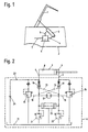
- Fig. 1 shows a schematic arrangement according to the present Invention in a vehicle
- Fig. 2 shows a schematic hydraulic Circuit diagram of an arrangement according to the invention.
- FIG. 1 The arrangement shown in Fig. 1 for hydraulic actuation of a Cover flap, a boot lid or other movable vehicle part 1 on a vehicle 2 has at least one double-acting hydraulic Working cylinder 3 on the one hand on the vehicle 2 and on the other the cover flap 1 is articulated.
- the workrooms not shown here of the working cylinder 3 are via lines 4, 5 with a hydraulic unit 6 connected, which via a connecting line 7 with the electrical Vehicle 2 electrical system is connected.
- the working cylinder 3 is also fixed relative to the vehicle 2 could be mounted.
- the 2 is the combination of hydraulic unit 6 and Lines 4, 5 connected cylinder 3 shown in more detail.
- the two working spaces 8, 9 of the working cylinder 3 are via the lines 4, 5 and each with a check valve 10, 11 arranged in the hydraulic unit 6 one side of a switchable pressure source 12 (formed here Pump including drive motor) in connection.
- the two check valves 10, 11 are connected via lines 13, 14 and can be unlocked from each other. about one bias valve 15, 16, the two working spaces 8, 9 are parallel to the check valves 10, 11 are shut off into the tank 17 as soon as an adjustable one Pressure levels are reached or exceeded.
- the preload valves 15, 16 are via lines 18, 19 and the pump side in front of the check valves 10, 11 prevailing pressure can be shut off hydraulically.
- the function of the arrangement shown is as in FIG. 2 illustrated explained.
- the Working cylinder 3 off or on.
- the motor of the pump of the pressure source 12 is energized, the pump runs and supplies pressure medium via the check valves 10 or 11 in the piston-side working space 8 or the rod-side Working room 9. This is on the same side via lines 18 and 19 such as the bias valve 15 or 16 controlled.
- the pressure in the work room 8 or 9 can be up to Build the required value.
- the cover flap 1 (Fig. 1) opens or closes hydraulically up to the stop in the working cylinder 3.
- the volume of the rod-side work space 9 flows when opening via the line 14 hydraulically controlled check valve 11 and the shuttle valve 20 in the tank 16 off.
- the hydraulic system delivers the total pressure relief valve 21 or 22 adjustable force.
- the pump runs until the cover flap 1 is open and is then switched off.
- a cover flap 1 according to FIG. 1 could be the inventive arrangement of course also for the actuation of vertical ones when closed Tailgates can be used for example a station wagon or a bus.
- Other application examples would be e.g. Vehicle doors, maintenance or ventilation flaps and the like.
Landscapes
- Engineering & Computer Science (AREA)
- Physics & Mathematics (AREA)
- Fluid Mechanics (AREA)
- Mechanical Engineering (AREA)
- General Engineering & Computer Science (AREA)
- Superstructure Of Vehicle (AREA)
- Lock And Its Accessories (AREA)
- Actuator (AREA)
- Vehicle Cleaning, Maintenance, Repair, Refitting, And Outriggers (AREA)
- Power-Operated Mechanisms For Wings (AREA)
- Fluid-Pressure Circuits (AREA)
Description
Claims (2)
- Anordnung zur hydraulischen Betätigung eines Heckdeckels, einer Abdeckklappe od. dgl. (1) an einem Fahrzeug, mit zumindest einem doppeltwirkenden hydraulischen Arbeitszylinder (3), der einerseits am Fahrzeug und andererseits an der Abdeckklappe angelenkt ist und dessen Arbeitsräume (8, 9) über je ein Rückschlagventil (10, 11) mit jeweils einer Seite einer umschaltbaren Druckquelle (12) in Verbindung stehen, wobei die beiden Rückschlagventile eine gegenseitige Entsperreinrichtung aufweisen und jeder der Arbeitsräume parallel zu den Rückschlagventilen über ein in den Tank absteuerndes Vorspannventil (15, 16) auf einem bestimmten Druckniveau gehalten ist , dadurch gekennzeichnet, daß zwischen zumindest einem Arbeitsraum (8, 9), vorzugsweise dem kolbenseitigen Arbeitsraum (8), und dem zugehörigen entsperrbaren Rückschlagventil (10 und/oder 11) eine zum Tank (17) führende, separate Nachsaugleitung (23) einmündet, in welche ein zum Arbeitsraum (8 und-/oder 9) hin öffnendes Rückschlagventil (24) eingesetzt ist.
- Anordnung nach Anspruch 1, dadurch gekennzeichnet, daß die Nachsaugleitung (23) zwischen dem jeweiligen Arbeitsraum (8, 9) und dem nächstliegenden hydraulischen Bauelement (10, 11) einmündet.
Applications Claiming Priority (2)
| Application Number | Priority Date | Filing Date | Title |
|---|---|---|---|
| AT88298 | 1998-05-22 | ||
| AT0088298A AT405750B (de) | 1998-05-22 | 1998-05-22 | Anordnung zur hydraulischen betätigung eines heckdeckels |
Publications (3)
| Publication Number | Publication Date |
|---|---|
| EP0959216A2 EP0959216A2 (de) | 1999-11-24 |
| EP0959216A3 EP0959216A3 (de) | 2003-05-14 |
| EP0959216B1 true EP0959216B1 (de) | 2004-09-01 |
Family
ID=3502006
Family Applications (1)
| Application Number | Title | Priority Date | Filing Date |
|---|---|---|---|
| EP99890103A Expired - Lifetime EP0959216B1 (de) | 1998-05-22 | 1999-03-24 | Anordnung zur hydraulischen Betätigung eines Heckdeckels |
Country Status (5)
| Country | Link |
|---|---|
| US (1) | US6217105B1 (de) |
| EP (1) | EP0959216B1 (de) |
| JP (1) | JP2000161306A (de) |
| AT (1) | AT405750B (de) |
| DE (1) | DE59910374D1 (de) |
Families Citing this family (16)
| Publication number | Priority date | Publication date | Assignee | Title |
|---|---|---|---|---|
| NL1011852C2 (nl) † | 1999-04-21 | 2000-10-24 | Applied Power Inc | Hydraulische bedieningsinrichting voor een afdekkapsamenstel van een voertuig. |
| AT408792B (de) * | 1999-11-22 | 2002-03-25 | Hoerbiger Hydraulik | Hydraulische betätigungsanordnung |
| KR20020028320A (ko) * | 2000-10-09 | 2002-04-17 | 이계안 | 버스의 도어 개폐장치 |
| AT410010B (de) * | 2001-01-29 | 2003-01-27 | Hoerbiger Hydraulik | Hydraulische betätigungsanordnung und hydraulisch sperrbares rückschlagventil |
| DE10119340A1 (de) * | 2001-04-20 | 2002-10-31 | Stabilus Gmbh | Betätigungssystem für eine Klappe o. dergleichen |
| FR2834528B1 (fr) * | 2002-01-04 | 2004-02-20 | France Design | Dispositif adapte a commander l'ouverture et la fermeture d'un capot de coffre |
| US6857686B2 (en) | 2003-02-06 | 2005-02-22 | Asc Incorporated | Two-way opening decklid for a convertible roof vehicle |
| US7198318B2 (en) * | 2003-03-24 | 2007-04-03 | Asc Incorporated | Retractable roof structural system |
| US20050006156A1 (en) * | 2003-07-10 | 2005-01-13 | Schambach Darren M. | Hood positioning apparatus and method |
| FI20060450A7 (fi) * | 2006-05-09 | 2007-11-10 | Huhtasalo Jouko | Järjestelmä toimisylinterin asemoimiseksi, järjestelmän käyttö ja työkone |
| DE102016015093A1 (de) | 2016-12-17 | 2017-06-29 | Daimler Ag | Antriebseinrichtung für ein Flügelelement eines Fahrzeugs, sowie Halteanordnung eines solchen Flügelelements an einem Aufbau eines Fahrzeugs |
| DE102017121501B3 (de) | 2017-09-15 | 2018-08-23 | Hoerbiger Automotive Komfortsysteme Gmbh | Kraftfahrzeug |
| DE102017121499B3 (de) | 2017-09-15 | 2018-08-16 | Hoerbiger Automotive Komfortsysteme Gmbh | Kraftfahrzeug |
| CN107905666A (zh) * | 2017-11-07 | 2018-04-13 | 宁波汉商液压有限公司 | 一种控制汽车电动尾门的液压系统 |
| CN113216785B (zh) * | 2021-05-28 | 2022-12-23 | 山东通华专用车辆股份有限公司 | 一种不完全开启的自动升降后门 |
| CN114001070A (zh) * | 2021-11-26 | 2022-02-01 | 武汉海王机电工程技术有限公司 | 一种双作用油缸液压控制管路及装置 |
Family Cites Families (15)
| Publication number | Priority date | Publication date | Assignee | Title |
|---|---|---|---|---|
| US2467509A (en) * | 1944-11-28 | 1949-04-19 | Bendix Aviat Corp | Hydraulic system |
| US3266381A (en) * | 1964-12-14 | 1966-08-16 | Gen Motors Corp | Control valve for vehicle closure operator system |
| US4359119A (en) * | 1979-05-04 | 1982-11-16 | New York Development Consultants, Ltd. | Spring-assisted elongated mass over-center system |
| DE3151070C2 (de) * | 1981-12-23 | 1994-07-14 | Stabilus Gmbh | Sicherheits-Gasfeder für Motorhauben und/oder Kofferraumklappen von Kraftfahrzeugen |
| JPS60121115A (ja) * | 1983-12-01 | 1985-06-28 | Toyota Motor Corp | 自動車用動力式コンバ−チブル・ル−フの制御装置 |
| DE3413380A1 (de) * | 1984-04-10 | 1985-10-17 | Dr.Ing.H.C. F. Porsche Ag, 7000 Stuttgart | Vorrichtung zum oeffnen und schliessen eines verdecks eines kraftfahrzeuges |
| US4688844A (en) * | 1984-04-18 | 1987-08-25 | Mazda Motor Corporation | Back door structures for motor vehicles |
| US4858981A (en) * | 1988-06-20 | 1989-08-22 | Post Herman D | Vehicle loading attachment |
| US5279119A (en) * | 1991-02-25 | 1994-01-18 | Wickes Manufacturing Company | Hydraulic lock and bypass for vehicle hydraulic system |
| US5110175A (en) * | 1991-07-26 | 1992-05-05 | Wickes Manufacturing Company | Convertible with automatic window operation |
| AT399130B (de) * | 1992-03-18 | 1995-03-27 | Hoerbiger Fluidtechnik Gmbh | Anordnung zur hydraulischen betätigung eines fahrzeugverdeckes |
| NL9401191A (nl) * | 1994-07-20 | 1996-03-01 | Applied Power Inc | Hydraulische schakeling. |
| KR970005252U (ko) * | 1995-07-19 | 1997-02-19 | 자동차의 루프 레일 엔드 커버 결합 구조 | |
| AT403785B (de) * | 1996-04-24 | 1998-05-25 | Hoerbiger Gmbh | Hydraulische betätigungsanordnung |
| EP0893605B1 (de) * | 1997-07-23 | 2002-10-09 | Hoerbiger Hydraulik GmbH | Hydraulische Betätigungsanordnung |
-
1998
- 1998-05-22 AT AT0088298A patent/AT405750B/de not_active IP Right Cessation
-
1999
- 1999-03-24 DE DE59910374T patent/DE59910374D1/de not_active Expired - Lifetime
- 1999-03-24 EP EP99890103A patent/EP0959216B1/de not_active Expired - Lifetime
- 1999-05-19 JP JP11139115A patent/JP2000161306A/ja active Pending
- 1999-05-21 US US09/316,018 patent/US6217105B1/en not_active Expired - Fee Related
Also Published As
| Publication number | Publication date |
|---|---|
| EP0959216A2 (de) | 1999-11-24 |
| US6217105B1 (en) | 2001-04-17 |
| AT405750B (de) | 1999-11-25 |
| DE59910374D1 (de) | 2004-10-07 |
| ATA88298A (de) | 1999-03-15 |
| EP0959216A3 (de) | 2003-05-14 |
| JP2000161306A (ja) | 2000-06-13 |
Similar Documents
| Publication | Publication Date | Title |
|---|---|---|
| EP0803630B1 (de) | Hydraulische Betätigungsanordnung | |
| EP0959216B1 (de) | Anordnung zur hydraulischen Betätigung eines Heckdeckels | |
| DE4233994A1 (de) | Hydraulische betaetigungsanordnung | |
| DE102012011273B3 (de) | Mobiler Großventilator | |
| EP0959217B1 (de) | Anordnung zur hydraulischen Betätigung eines Heckdeckels | |
| EP1101692B1 (de) | Hydraulische Betätigungsanordnung | |
| AT408208B (de) | Anordnung zur hydraulischen betätigung eines bewegten teils an fahrzeugen, insbesondere eines verdecks, eines heckdeckels, einer abdeckklappe oder dgl. | |
| AT396613B (de) | Hydraulische betätigungsanordnung für ein fahrzeugverdeck | |
| AT406072B (de) | Hydraulische betätigungsanordnung | |
| EP1279541A1 (de) | Verfahren und Vorrichtung zur Betätigung eines Verdecksystems bei Fahrzeugen | |
| DE102004031202B4 (de) | Hydrauliksystem zum Hochschwenken und Herablassen von Flügel-Aufbauteilen eines Lkws | |
| EP1404976B1 (de) | Hydraulische betätigungsanordnung und hydraulisch sperrbares rückschlagventil | |
| DE10220455B4 (de) | Hydraulische Betätigungsvorrichtung für ein Verdeck mit zugehörigem Riegel | |
| EP1162375A2 (de) | Betätigungsanordnung für schwenkbare Teile an Fahrzeugen | |
| DE102021105025A1 (de) | Schwenkantrieb für Durchladezug | |
| EP0893605B1 (de) | Hydraulische Betätigungsanordnung | |
| DE102005005891B4 (de) | Tür mit Türbremse | |
| CH717147A2 (de) | Hydraulischer Servo-Aktuator. | |
| AT405752B (de) | Anordnung zur hydraulischen betätigung eines heckdeckels | |
| CH502202A (de) | Kraftfahrzeug mit eine Be- und/oder Entladeöffnung an einer Vertikalseite verschliessender Klapptür | |
| AT405751B (de) | Anordnung zur hydraulischen betätigung eines heckdeckels | |
| AT406357B (de) | Anordnung zur hydraulischen betätigung eines verdecks, eines heckdeckels od. dgl. | |
| AT409399B (de) | Hydraulische betätigungsanordnung | |
| DE102017121499B3 (de) | Kraftfahrzeug | |
| DE102017121501B3 (de) | Kraftfahrzeug |
Legal Events
| Date | Code | Title | Description |
|---|---|---|---|
| PUAI | Public reference made under article 153(3) epc to a published international application that has entered the european phase |
Free format text: ORIGINAL CODE: 0009012 |
|
| AK | Designated contracting states |
Kind code of ref document: A2 Designated state(s): AT BE CH CY DE DK ES FI FR GB GR IE IT LI LU MC NL PT SE |
|
| AX | Request for extension of the european patent |
Free format text: AL;LT;LV;MK;RO;SI |
|
| PUAL | Search report despatched |
Free format text: ORIGINAL CODE: 0009013 |
|
| AK | Designated contracting states |
Designated state(s): AT BE CH CY DE DK ES FI FR GB GR IE IT LI LU MC NL PT SE |
|
| AX | Request for extension of the european patent |
Extension state: AL LT LV MK RO SI |
|
| RIC1 | Information provided on ipc code assigned before grant |
Ipc: 7E 05F 15/00 B Ipc: 7B 62D 25/12 B Ipc: 7E 05F 15/04 A |
|
| 17P | Request for examination filed |
Effective date: 20030604 |
|
| AKX | Designation fees paid |
Designated state(s): DE FR IT |
|
| GRAP | Despatch of communication of intention to grant a patent |
Free format text: ORIGINAL CODE: EPIDOSNIGR1 |
|
| GRAS | Grant fee paid |
Free format text: ORIGINAL CODE: EPIDOSNIGR3 |
|
| GRAA | (expected) grant |
Free format text: ORIGINAL CODE: 0009210 |
|
| AK | Designated contracting states |
Kind code of ref document: B1 Designated state(s): DE FR IT |
|
| PG25 | Lapsed in a contracting state [announced via postgrant information from national office to epo] |
Ref country code: IT Free format text: LAPSE BECAUSE OF FAILURE TO SUBMIT A TRANSLATION OF THE DESCRIPTION OR TO PAY THE FEE WITHIN THE PRE;WARNING: LAPSES OF ITALIAN PATENTS WITH EFFECTIVE DATE BEFORE 2007 MAY HAVE OCCURRED AT ANY TIME BEFORE 2007. THE CORRECT EFFECTIVE DATE MAY BE DIFFERENT FROM THE ONE RECORDED.SCRIBED TIME-LIMIT Effective date: 20040901 |
|
| REG | Reference to a national code |
Ref country code: IE Ref legal event code: FG4D Free format text: GERMAN |
|
| REF | Corresponds to: |
Ref document number: 59910374 Country of ref document: DE Date of ref document: 20041007 Kind code of ref document: P |
|
| REG | Reference to a national code |
Ref country code: IE Ref legal event code: FD4D |
|
| PLBE | No opposition filed within time limit |
Free format text: ORIGINAL CODE: 0009261 |
|
| STAA | Information on the status of an ep patent application or granted ep patent |
Free format text: STATUS: NO OPPOSITION FILED WITHIN TIME LIMIT |
|
| ET | Fr: translation filed | ||
| 26N | No opposition filed |
Effective date: 20050602 |
|
| PGFP | Annual fee paid to national office [announced via postgrant information from national office to epo] |
Ref country code: FR Payment date: 20090303 Year of fee payment: 11 |
|
| REG | Reference to a national code |
Ref country code: FR Ref legal event code: ST Effective date: 20101130 |
|
| PG25 | Lapsed in a contracting state [announced via postgrant information from national office to epo] |
Ref country code: FR Free format text: LAPSE BECAUSE OF NON-PAYMENT OF DUE FEES Effective date: 20100331 |
|
| PGFP | Annual fee paid to national office [announced via postgrant information from national office to epo] |
Ref country code: DE Payment date: 20150528 Year of fee payment: 17 |
|
| REG | Reference to a national code |
Ref country code: DE Ref legal event code: R119 Ref document number: 59910374 Country of ref document: DE |
|
| PG25 | Lapsed in a contracting state [announced via postgrant information from national office to epo] |
Ref country code: DE Free format text: LAPSE BECAUSE OF NON-PAYMENT OF DUE FEES Effective date: 20161001 |