EP0959213B1 - Structure de porte d'accès pivotante d'ordinateur ayant un dispositif de charnière séparable - Google Patents
Structure de porte d'accès pivotante d'ordinateur ayant un dispositif de charnière séparable Download PDFInfo
- Publication number
- EP0959213B1 EP0959213B1 EP99303928A EP99303928A EP0959213B1 EP 0959213 B1 EP0959213 B1 EP 0959213B1 EP 99303928 A EP99303928 A EP 99303928A EP 99303928 A EP99303928 A EP 99303928A EP 0959213 B1 EP0959213 B1 EP 0959213B1
- Authority
- EP
- European Patent Office
- Prior art keywords
- hinge
- access door
- housing
- portions
- end portions
- Prior art date
- Legal status (The legal status is an assumption and is not a legal conclusion. Google has not performed a legal analysis and makes no representation as to the accuracy of the status listed.)
- Expired - Lifetime
Links
Images


Classifications
-
- H—ELECTRICITY
- H05—ELECTRIC TECHNIQUES NOT OTHERWISE PROVIDED FOR
- H05K—PRINTED CIRCUITS; CASINGS OR CONSTRUCTIONAL DETAILS OF ELECTRIC APPARATUS; MANUFACTURE OF ASSEMBLAGES OF ELECTRICAL COMPONENTS
- H05K7/00—Constructional details common to different types of electric apparatus
- H05K7/14—Mounting supporting structure in casing or on frame or rack
- H05K7/16—Mounting supporting structure in casing or on frame or rack on hinges or pivots
-
- G—PHYSICS
- G06—COMPUTING; CALCULATING OR COUNTING
- G06F—ELECTRIC DIGITAL DATA PROCESSING
- G06F1/00—Details not covered by groups G06F3/00 - G06F13/00 and G06F21/00
- G06F1/16—Constructional details or arrangements
- G06F1/18—Packaging or power distribution
- G06F1/181—Enclosures
-
- E—FIXED CONSTRUCTIONS
- E05—LOCKS; KEYS; WINDOW OR DOOR FITTINGS; SAFES
- E05D—HINGES OR SUSPENSION DEVICES FOR DOORS, WINDOWS OR WINGS
- E05D1/00—Pinless hinges; Substitutes for hinges
- E05D1/06—Pinless hinges; Substitutes for hinges consisting of two easily-separable parts
-
- E—FIXED CONSTRUCTIONS
- E05—LOCKS; KEYS; WINDOW OR DOOR FITTINGS; SAFES
- E05D—HINGES OR SUSPENSION DEVICES FOR DOORS, WINDOWS OR WINGS
- E05D7/00—Hinges or pivots of special construction
- E05D7/10—Hinges or pivots of special construction to allow easy separation or connection of the parts at the hinge axis
- E05D7/1044—Hinges or pivots of special construction to allow easy separation or connection of the parts at the hinge axis in an axial direction
- E05D7/105—Hinges or pivots of special construction to allow easy separation or connection of the parts at the hinge axis in an axial direction requiring a specific angular position
-
- E—FIXED CONSTRUCTIONS
- E05—LOCKS; KEYS; WINDOW OR DOOR FITTINGS; SAFES
- E05D—HINGES OR SUSPENSION DEVICES FOR DOORS, WINDOWS OR WINGS
- E05D7/00—Hinges or pivots of special construction
- E05D7/10—Hinges or pivots of special construction to allow easy separation or connection of the parts at the hinge axis
- E05D7/1044—Hinges or pivots of special construction to allow easy separation or connection of the parts at the hinge axis in an axial direction
- E05D7/1055—Hinges or pivots of special construction to allow easy separation or connection of the parts at the hinge axis in an axial direction with snap-fitted pins
-
- E—FIXED CONSTRUCTIONS
- E05—LOCKS; KEYS; WINDOW OR DOOR FITTINGS; SAFES
- E05Y—INDEXING SCHEME RELATING TO HINGES OR OTHER SUSPENSION DEVICES FOR DOORS, WINDOWS OR WINGS AND DEVICES FOR MOVING WINGS INTO OPEN OR CLOSED POSITION, CHECKS FOR WINGS AND WING FITTINGS NOT OTHERWISE PROVIDED FOR, CONCERNED WITH THE FUNCTIONING OF THE WING
- E05Y2900/00—Application of doors, windows, wings or fittings thereof
- E05Y2900/60—Application of doors, windows, wings or fittings thereof for other use
- E05Y2900/606—Application of doors, windows, wings or fittings thereof for other use for electronic devices
-
- Y—GENERAL TAGGING OF NEW TECHNOLOGICAL DEVELOPMENTS; GENERAL TAGGING OF CROSS-SECTIONAL TECHNOLOGIES SPANNING OVER SEVERAL SECTIONS OF THE IPC; TECHNICAL SUBJECTS COVERED BY FORMER USPC CROSS-REFERENCE ART COLLECTIONS [XRACs] AND DIGESTS
- Y10—TECHNICAL SUBJECTS COVERED BY FORMER USPC
- Y10S—TECHNICAL SUBJECTS COVERED BY FORMER USPC CROSS-REFERENCE ART COLLECTIONS [XRACs] AND DIGESTS
- Y10S16/00—Miscellaneous hardware, e.g. bushing, carpet fastener, caster, door closer, panel hanger, attachable or adjunct handle, hinge, window sash balance
- Y10S16/13—Plastic hinge
Definitions
- the present invention generally relates to electronic devices such as computers and, in a preferred embodiment thereof, more particularly relates to access door structures installed on computer housings.
- the housings of electronic devices such as computers are often formed of a molded plastic material and provided with exterior openings to afford user access to devices within the housing.
- An example of such a housing opening is a tower type computer drive bay opening extending through an outer front bezel portion of the computer housing structure.
- Housing openings of this sort are typically provided with an access door structure, also commonly of a molded plastic material, to selectively block and expose the housing opening.
- a common type of access door is one that is rotatably secured to the housing bezel, by a hinge structure, for pivotal movement relative thereto between (1) a closed position, in which the door extends across and covers the housing opening, and (2) an outwardly pivoted open limit position in which the opening is uncovered and the door is precluded from further opening movement by the abutment of an inner edge portion thereof with a facing portion of the bezel.
- Hinged molded plastic access doors of this type are typically subject to several well known problems, limitations and disadvantages. For example, many of the access doors have exposed hinge structures which are subject to damage and tend to be unsightly. Other previously utilized access doors cannot be outwardly pivoted past about ninety degrees from their closed positions, thereby often hindering access to their associated bezel opening.
- Each hinge arm was formed from two releasably telescoped longitudinal sections which, when the door was pivoted outwardly past its open limit position, were designed to longitudinally separate from one another to permit the door and the inner hinge arm sections to break away from the ouster hinge arm sections, without damage thereto, in a manner permitting the undamaged door to be replaced on the bezel by re-telescoping the inner and outer hinge arm sections.
- This design is relatively complex and expensive, and does not provide consistent damage-free break-away action for the access door.
- US-A-4302866 discloses a releasable hinge for swingable portions such a cover and bottom of a container or the like.
- a need exists for a pivotally supported computer housing opening access door which has a concealed hinge structure, has a total closed-to-fully open pivotal travel range of more than ninety degrees, and has damage free break-away and replacement capabilities.
- an electronic device comprising:
- the break-away hinge structure also includes a disconnect structure which is laterally offset from the hinge pivot axis and operates, in response to forcibly pivoting the access door outwardly beyond its open limit position, to create on one of the first and second hinge portions a resilient camming force which disengages it from the other hinge portion.
- this camming force resiliently deflects one of the first and second hinge portions generally parallel to the pivot axis of the hinge structure.
- the hinge structure is concealed from view when the access door is closed, and permits the access door to be supported for pivotal movement between its closed and open limit positions through a rotational arc greater than ninety degrees to improve access to the housing wall opening.
- the first hinge portion includes spaced first and second hinge arm members with body portions extending outwardly from the access door in first directions and having lateral cutout portions therein which facilitate the concealment of the hinge structure and the ability of the access door to pivot outwardly beyond ninety degrees to its open limit position.
- body portions At the outer ends these body portions are transverse mounting tabs which have circular mounting holes in their outer ends.
- the access door and the two hinge arms are integral portions of a plastic molding.
- the second hinge portion includes first and second hinge pin members, space apart along the pivot axis, which are preferably recessed in spaced apart hinge pocket areas of the housing wall structure and preferably have domed outer ends. With the access door operatively attached to the housing, these hinge pins are rotatably received in the hinge arm tab openings and support the access door for pivotal movement between its closed and open limit positions relative to the housing.
- the disconnect structure representatively includes (1) a pair of disconnect pin members each positioned in a spaced apart, parallel relationship with one of the hinge pins, laterally offset from the hinge pivot axis, and having a domed outer end, and (2) a sloping cam surface formed on each of the hinge arm tabs and cammingly engageable by one of the domed outer ends of the disconnect pin members, in response to forcible pivotal movement of the access door outwardly beyond its open limit position, in a manner deflecting the hinge arm tabs generally parallel to the pivot axis and out of engagement with the hinge pins to thereby detach the access door from the housing.
- the detached access door may be easily and quickly remounted on the housing by pressing sloping "lead-in" surfaces on the hinge arm tabs, adjacent the hinge pin openings therein, against the domed outer ends of the hinge pins to cause the tabs to be resiliently deflected, in directions generally parallel to the pivot axis, in a manner permitting the hinge pins to slide along the tabs and then operatively snap back into their hinge pin openings.
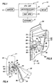
- FIG. 1 Schematically illustrated in FIG. 1 is a representative computer system 10, the components of which are interconnected as shown and include a computer, illustratively in the form of a tower type CPU unit 11; a monitor 12; a keyboard 13; and a pointing device, representatively in the form of a mouse 14.
- the CPU unit 11 has a data storage device, representatively a disk drive 16, for storing data that may be retrieved by a microprocessor 18 within the CPU unit 11.
- the CPU unit 11 has a generally rectangular housing portion 20 with a vertical front side portion being defined by a molded plastic bezel structure 22.
- a generally rectangular opening Formed in an upper portion of the bezel 22 is a generally rectangular opening, representatively a drive bay opening 24.
- a generally rectangular molded plastic access door 26 is provided. Access door 26 is removably secured to the bezel 22 by a specially designed concealed, break-away hinge structure 28 (see FIGS. 2B, 4 and 5) which embodies principles of the present invention.
- Hinge structure 28 removably mounts the access door 26 on the front bezel structure 22 for pivotal motion relative thereto, about a vertical pivot axis 30 (see FIGS. 3 and 5) between a closed position in which the access door 26 covers the housing wall structure opening 24 (see FIG. 2A), and an open limit position (see FIGS. 2B and 4) in which the access door 26 uncovers the opening 24.
- the access door 26 In its open limit position, the access door 26 is swung outwardly from its closed position through a rotational arc of more than ninety degrees, with an inturned inner side edge lip 32 of the door 26 (see FIGS. 2B, 3 and 4) bearing against a facing vertical outer right side wall portion 34 of the bezel 22 and blocking further outward pivotal movement of the opened door 26.
- a conventional push-push type latch structure is provided for releasably holding the access door 26 in its closed position over the drive bay opening 24.
- This conventional latch structure includes a latch projection 36 formed on the inner side 38 of the access door 26, and a recessed detent structure 40 disposed on a front side of the bezel 22 outwardly adjacent the left side of the drive bay opening 24.
- the projection 36 is received and releasably locked within the recessed detent structure 40.
- the detent structure 40 automatically releases the projection 36 and allows the door 26 to again be swung outwardly to its FIG. 2B open limit position.
- the specially designed hinge structure 28 permits the access door 26 to simply pop off the bezel structure 22 without appreciably damaging the bezel structure 22, the access door 26 or the hinge structure 28.
- the unique concealed hinge structure 28 also permits the detached access door 26 to be simply and quickly snapped back into operative pivotal mounting engagement with the bezel structure 22 without requiring tools of any sort.
- the hinge structure 28 includes (1) upper and lower elongated hinge arm members 42,44 longitudinally extending inwardly from the inner side surface 38 of the access door 26 adjacent its inner side edge lip 32 (see FIGS. 2B-5); (2) upper and lower hinge pin members 46,48 (see FIGS. 2B-5) which are formed on the bezel structure 22, vertically spaced apart along the pivot axis 30, and respectively disposed in forwardly opening upper and lower hinge pockets 50,51 formed in a vertical front side wall portion 52 of the bezel 22 adjacent upper and lower inner side notches 53a,53b in its side wall portion 34 (see FIGS. 3 and 4); and (3) upper and lower disconnect pin members 54,56 which are formed on the bezel structure 22 in the indicated parallel, laterally spaced relationships with the hinge pins 46,48 in the upper and lower pocket areas 50 and 51.
- Each of the upper and lower hinge arms 42,44 is preferably molded as an integral part of the plastic access door 26 and has a relatively small vertical thickness, a longitudinally intermediate cutout area 58 horizontally extending into the hinge arm body and forming a narrowed body portion 60 in the hinge arm, and a horizontally projecting transverse outer tab portion 62 which is generally perpendicular to the longitudinal axis 64 of the body portion 60 and to the pivot axis 30.
- Extending vertically through the outer end of each tab portion 62 is a vertically oriented tubular portion 66 with a circularly cross-sectioned mounting opening 68 extending axially therethrough.
- each of the hinge arm tubular portions 66 has a rear outer side surface 70 thereon (see FIGS. 3 and 5) which is sloped relative to the pivot axis 30.
- the upper tubular portion side surface 70 is sloped upwardly and forwardly relative to the rear or inner side surface 38 of the access door 26, and the lower tubular portion side surface 70 is sloped downwardly and forwardly relative to the rear side surface 38 of the access door 26.
- a pair of ramped disconnect surfaces 72 are formed on the outer ends of the hinge arm tabs 62 rearwardly of their tubular portions 66.
- the ramped disconnect surfaces 72 face rightwardly as viewed from the rear side of the access door 26 in FIG. 3, with the upper ramped disconnect surface 72 being sloped downwardly and rightwardly, and the lower ramped disconnect surface 72 sloping upwardly and rightwardly.
- the free lower ends of the upper pins 46 and 54, and the free upper ends of the lower pins 48 and 56 are domed as at 74.
- the upper pin members 46,54 extend downwardly from an upper wall portion 50a of the upper hinge pocket 50 (see FIG. 3), and the lower pin members 48,56 extend upwardly from a bottom wall portion 51 a of the lower hinge pocket 51.
- the upper and lower hinge pins 46 and 48 which are slightly longer than the upper and lower disconnect pins 54 and 56, are pivotally and removably received in the circular openings 68 in the hinge arm tab portions 62 and form with the interior surfaces of the openings 68 upper and lower pivot locations spaced apart along the vertical pivot axis 30.
- the upper hinge pin 46 extends downwardly into the tab opening 68 of the upper hinge arm 42, and the lower hinge pin 48 extends upwardly into the tab opening 68 of the lower hinge arm 44.
- the cutout areas 58 in the upper and lower hinge arms 42,44 facilitate the access door 26 being able to be outwardly rotated from its closed position through an arc of more than ninety degrees, to provide easier insertion and removal access to the drive bay opening 24, by permitting a forward edge section of the bezel wall portion 34 to enter the cutout areas 58.
- the notches 53 in the front edge of the bezel wall portion 34 also facilitate this pivoting past the ninety degree mark, as additionally illustrated in FIG. 4.
- the hinge structure 28 is completely concealed from view behind the closed door 26. This hinge structure concealment is facilitated by the tab cutout areas 58 which permit the hinge pins 46,48 to be rearwardly recessed into the upper and lower hinge pockets 50 and 51.
- an additional advantage provided by the hinge structure 28 is that it permits the access door 26 to be “broken away” from the bezel structure 22, and then replaced thereon, without damage to the bezel structure 22, the access door 26 or the hinge structure 28 when the door 26 is inadvertently (or intentionally) pivoted outwardly past its solid line open limit position (as indicated by the arrow 41 in FIG. 4) to the door's dashed line detached position also shown in FIG. 4.
- the upper and lower disconnect pins 54,56 form with the ramped surfaces 72 on the tab portions 62 of the upper and lower hinge arms 42,44 a disconnect portion of the hinge structure 28. As illustrated, this disconnect portion, relative to the pivot axis 30, is laterally offset from the hinge pin/hinge arm pivot locations.
- rear portions of the domed outer end surfaces 74 of the upper and lower disconnect pins 54,56 are positioned in front of and engage the ramped surfaces 72 on the tab portions 62 of the upper and lower hinge arms 42 and 44.
- FIG. 5 when the access door 26 is closed, these ramped hinge arm tab surfaces 72 are pivoted out of engagement with the disconnect pins 54 and 56.
- this causes the tabs 62 to be deflected toward one another along the pivot axis 30, as indicated by the arrows 80 in FIGS. 3 and 5, to disengage the upper and lower hinge arm tabs 62 from the upper and lower hinge pins 46 and 48 and detaching the access door 26 from the bezel 22 without damaging the bezel 22, the access door 26 or the hinge structure 28.
- the hinge arm tabs 62 After the hinge arm tabs 62 are disconnected from the hinge pins 46,48 the deflected tabs 62 simply spring back to their original positions as shown in FIG. 3.
Claims (10)
- Un dispositif électronique (11) comprenant :un boítier (20), comportant une ouverture de paroi (24) sur celui-ci ;une porte d'accès (26) ;une première et une seconde parties de charnière (28) respectivement portées par ladite porte d'accès (26) et ledit boítier (20) et inter engagées, de manière libérable, sur des emplacements de pivot espacés le long d'un axe de pivot (30), lesdites première et seconde parties de charnière (28) supportant ladite porte d'accès (26) en vue d'un mouvement pivotant par rapport au dit boítier (20), autour dudit axe de pivot (30), entre une position fermée (41) et une position d'ouverture limite dans laquelle ladite porte d'accès (26) respectivement recouvre et découvre ladite ouverture de paroi (24) ; et caractérisé parune structure de déconnexion (54, 56, 62, 72, 74) décalée desdits emplacements de pivot et comprenant une surface à came (72, 74) fonctionnant pour désengager lesdites première et seconde parties de charnière (28) en déplaçant au moins une des parties de charnière (28) le long de l'axe de pivot (30), afin de libérer, de ce fait, ladite porte d'accès (26) dudit boítier (20), en réponse à un pivotement en force de ladite porte d'accès (26) vers l'extérieur au-delà de ladite position d'ouverture limite (41).
- Un dispositif électronique (11) selon la revendication 1, dans lequel :ladite structure de déconnexion (54, 56, 62, 72, 74) fonctionne en utilisant la surface à came (72, 74) afin de faire dévier ladite première partie de charnière (28) en dehors d'un engagement avec ladite seconde partie de charnière (28) dans une direction généralement parallèle au dit axe de pivot (30).
- Un dispositif électronique (11) selon la revendication 2, dans lequel :ladite première partie de charnière comprend un premier et un second bras de charnière (42, 44) espacés l'un de l'autre, dépassant extérieurement de ladite porte d'accès (26), et comportant des parties d'extrémité externe avec des ouvertures formées dans celles-ci,ladite seconde partie de charnière comprend une paire d'axes de charnière (46, 48) portés par ledit boítier (20) et reçus, de manière à pouvoir tourner, dans lesdites ouvertures desdites parties d'extrémité externe de bras de charnière, etladite structure de déconnexion (54, 56, 62, 72, 74) comprend une première (74) et une seconde (72) parties de surface à came coopérantes, respectivement associées avec ledit boítier et lesdits bras de charnière, et pouvant être engagées en utilisant la surface à came (74) au cours d'un mouvement pivotant de ladite porte d'accès (26) vers l'extérieur au-delà de la position limite d'ouverture (41).
- Un dispositif électronique (11) selon la revendication 3, dans lequel ladite structure de déconnexion (54, 56, 62, 72, 74) comprend :une paire d'axes de déconnexion (54, 56) portés par ledit boítier (20), en parallèles et latéralement espacées desdits axes de charnière (46, 48), et comportant des parties d'extrémité en dôme définissant ladite première partie de surface à came (74) ; etune paire de surfaces inclinées (72) formées sur lesdites parties d'extrémité externe de bras de charnière, et définissant ladite seconde partie de surface à came.
- Un dispositif électronique (11) selon l'une quelconque des revendications 1 à 4, dans lequel ladite structure de déconnexion (54, 56, 62, 72, 74), par rapport au dit axe de pivot (30), est transversalement décalé desdits emplacements de pivot.
- Un dispositif électronique (11) selon la revendication 1, dans lequel :ladite première partie de charnière comprend un premier et un second bras de charnière (42, 44) espacés l'un de l'autre, dépassant extérieurement de ladite porte d'accès (26), et comportant des parties d'extrémité externe avec des ouvertures formées dans celles-ci,ladite seconde partie de charnière comprend une paire d'axes de charnière (46, 48) portés par ledit boítier (20) et reçus, de manière à pouvoir tourner, dans lesdites ouvertures desdites parties d'extrémité externe de bras de charnière, lesdits axes de charnière comportant des extrémités externes en dôme, etlesdites parties d'extrémité externe de bras de charnière comportent des surfaces inclinées (72) qui peuvent être forcées contre lesdites extrémités d'axe de charnière externe en dôme afin de faire dévier, de manière élastique, lesdites parties d'extrémité externe de bras de charnière d'une manière facilitant l'entrée desdits axes de charnière dans lesdites ouvertures dans lesdites parties d'extrémité externe de bras de charnière, afin d'attacher, de manière à pouvoir pivoter, ladite porte d'accès au dit boítier.
- Un dispositif électronique (11) selon la revendication 1, dans lequel :ladite structure de déconnexion (54, 56, 62, 72, 74) fonctionne afin de désengager lesdites première et seconde parties de charnière d'une manière laissant ladite seconde partie de charnière en place sur ledit boítier (20).
- Un ordinateur (10) doté d'une unité centrale de traitement (11) comprenant un microprocesseur, un dispositif de stockage de données, et un dispositif électronique selon l'une quelconque des revendications 1 à 7.
- Un ordinateur (10) selon la revendication 8, dans lequel ladite unité centrale de traitement (11) est une unité centrale de traitement en tour.
- Un ordinateur (10) selon la revendication 8 ou la revendication 9, dans lequel ladite ouverture de paroi (24) est une ouverture de baie de lecteurs de disque.
Applications Claiming Priority (2)
| Application Number | Priority Date | Filing Date | Title |
|---|---|---|---|
| US83791 | 1998-05-22 | ||
| US09/083,791 US6130822A (en) | 1997-06-09 | 1998-05-22 | Pivotable computer access door structure having concealed, Break-away hinge mechanism |
Publications (2)
| Publication Number | Publication Date |
|---|---|
| EP0959213A1 EP0959213A1 (fr) | 1999-11-24 |
| EP0959213B1 true EP0959213B1 (fr) | 2004-10-06 |
Family
ID=22180727
Family Applications (1)
| Application Number | Title | Priority Date | Filing Date |
|---|---|---|---|
| EP99303928A Expired - Lifetime EP0959213B1 (fr) | 1998-05-22 | 1999-05-20 | Structure de porte d'accès pivotante d'ordinateur ayant un dispositif de charnière séparable |
Country Status (6)
| Country | Link |
|---|---|
| US (1) | US6130822A (fr) |
| EP (1) | EP0959213B1 (fr) |
| JP (1) | JPH11346066A (fr) |
| KR (1) | KR19990088467A (fr) |
| DE (1) | DE69920797T2 (fr) |
| TW (1) | TW442720B (fr) |
Families Citing this family (40)
| Publication number | Priority date | Publication date | Assignee | Title |
|---|---|---|---|---|
| US6452788B1 (en) * | 2000-02-16 | 2002-09-17 | Micron Technology, Inc. | Computer housing with expansion bay cover and methods for operating expansion bay covers |
| KR100388670B1 (ko) | 2000-09-09 | 2003-06-25 | 삼성전자주식회사 | 컴퓨터 본체용 케이싱 |
| TW483651U (en) * | 2000-11-10 | 2002-04-11 | Hon Hai Prec Ind Co Ltd | Rotating device of computer panel |
| US6595605B1 (en) * | 2000-11-14 | 2003-07-22 | International Business Machines Corporation | Spring loaded latching for system enclosure panels |
| US6525929B2 (en) * | 2001-01-25 | 2003-02-25 | Dell Products L.P. | Computer chassis door with position damping detent hinge |
| US6603655B2 (en) * | 2001-08-03 | 2003-08-05 | Dell Products L.P. | Rotating and translating four bar media door for a computer chassis |
| US6519140B1 (en) * | 2001-09-13 | 2003-02-11 | Sun Microsystems, Inc. | Hinged bezel for a computer system |
| US6680843B2 (en) | 2001-09-28 | 2004-01-20 | International Business Machines Corporation | All-in-one personal computer with tool-less quick-release features for various elements thereof including a reusable thin film transistor monitor |
| US6834919B1 (en) * | 2001-11-01 | 2004-12-28 | Apple Computer, Inc. | Drive bay cover and eject bracket |
| US6658700B2 (en) * | 2001-11-02 | 2003-12-09 | Hewlett-Packard Development Company, L.P. | Hinged-bezel system for use with electronic devices |
| TW558033U (en) * | 2002-04-11 | 2003-10-11 | Avance Technologies Inc | Protection and heat sink device for computer data access equipment |
| US20040119384A1 (en) * | 2002-12-20 | 2004-06-24 | Davis Richard W. | Bezel assembly |
| TW547901U (en) * | 2002-12-24 | 2003-08-11 | Delta Electronics Inc | Rotatable and removable lifting lid |
| TW577567U (en) * | 2003-01-28 | 2004-02-21 | Shuttle Inc | Mask lid structure of computer host panel |
| US7131711B2 (en) * | 2003-02-12 | 2006-11-07 | Hon Hai Precision Ind. Co., Ltd. | Computer enclosure incorporating bezel pivoting mechanism |
| GB2408631A (en) * | 2003-11-25 | 2005-06-01 | Shin Cheng Ind Co Ltd | Pivotal bay cover on computer chassis front panel |
| CN2736839Y (zh) * | 2004-06-23 | 2005-10-26 | 鸿富锦精密工业(深圳)有限公司 | 具有输入/输出接口的面板 |
| US7017232B1 (en) | 2005-05-06 | 2006-03-28 | Priddy Thomas G | Load limiting hinge |
| CN2800354Y (zh) * | 2005-06-10 | 2006-07-26 | 鸿富锦精密工业(深圳)有限公司 | 电脑机箱后面板 |
| US20070153451A1 (en) * | 2005-12-29 | 2007-07-05 | Hon Hai Precision Industry Co., Ltd. | Mounting apparatus for computer power supply |
| US20070192992A1 (en) * | 2006-02-23 | 2007-08-23 | Steven Su | Cover module for a computer case |
| US9086737B2 (en) * | 2006-06-15 | 2015-07-21 | Apple Inc. | Dynamically controlled keyboard |
| DE102006057358B4 (de) | 2006-12-04 | 2019-05-02 | Mahle International Gmbh | Gelenkanordnung mit einer Clipsverbindung |
| CN101311875B (zh) * | 2007-05-22 | 2011-07-27 | 鸿富锦精密工业(深圳)有限公司 | 光驱挡板组合 |
| US20090127988A1 (en) * | 2007-11-20 | 2009-05-21 | Sergejs Lucuks | Device for a computer case cover |
| US8067701B2 (en) * | 2008-01-07 | 2011-11-29 | Apple Inc. | I/O connectors with extendable faraday cage |
| US7845953B2 (en) * | 2008-01-07 | 2010-12-07 | Apple Inc. | Input/output connector and housing |
| US8110744B2 (en) * | 2008-08-19 | 2012-02-07 | Apple Inc. | Flexible shielded cable |
| US8554042B2 (en) * | 2009-02-18 | 2013-10-08 | Commscope, Inc. | Optical fiber management shelf including door with push-push fastener |
| US8244942B2 (en) * | 2009-08-06 | 2012-08-14 | Hewlett-Packard Development Company, L.P. | Computer storage device adapter for installing a storage device in a computer drive bay |
| CN201515407U (zh) * | 2009-09-04 | 2010-06-23 | 深圳富泰宏精密工业有限公司 | 保护盖及具有该保护盖的便携式电子装置 |
| CN102221854A (zh) * | 2010-04-13 | 2011-10-19 | 鸿富锦精密工业(深圳)有限公司 | 光驱按键装置 |
| CN102149259B (zh) * | 2011-04-01 | 2013-06-12 | 鸿富锦精密工业(武汉)有限公司 | 面板 |
| US9253904B2 (en) * | 2012-10-22 | 2016-02-02 | Apple Inc. | Protective locking mechanism for device enclosure |
| CN104571374B (zh) * | 2013-10-21 | 2017-11-21 | 纬创资通股份有限公司 | 具有转动定位功能的电子装置 |
| CN105700633B (zh) * | 2014-11-26 | 2019-03-05 | 纬创资通股份有限公司 | 有定位功能的快拆旋转机构及有定位旋转门板的电子装置 |
| JP2020103623A (ja) * | 2018-12-27 | 2020-07-09 | パナソニックIpマネジメント株式会社 | 宅配ボックス |
| CN113260182B (zh) * | 2020-02-11 | 2022-06-28 | 纬联电子科技(中山)有限公司 | 旋转门结构及电子装置壳体 |
| WO2022093788A1 (fr) * | 2020-10-26 | 2022-05-05 | Parcel Safe Systems LLC | Système de coffre à colis |
| US11920396B2 (en) * | 2021-01-08 | 2024-03-05 | Snap-On Incorporated | Access door for a storage unit |
Family Cites Families (6)
| Publication number | Priority date | Publication date | Assignee | Title |
|---|---|---|---|---|
| US4302866A (en) * | 1980-01-18 | 1981-12-01 | The Quaker Oats Company | Releasable hinge for swingable portions of a container |
| US4391883A (en) * | 1981-09-28 | 1983-07-05 | Motorola, Inc. | Housing arrangement with breakaway battery access door |
| US5349132A (en) * | 1993-02-08 | 1994-09-20 | Apple Computer, Inc. | Methods and apparatus for modular computer construction |
| US5316168A (en) * | 1993-07-06 | 1994-05-31 | Motorola, Inc. | Door cover assembly |
| US5946055A (en) * | 1996-08-16 | 1999-08-31 | Rosen Product Development, Inc. | Display unit |
| US5815379A (en) * | 1997-06-09 | 1998-09-29 | Compaq Computer Corporation | Pivotable computer access door structure having concealed, break-away hinge mechanism |
-
1998
- 1998-05-22 US US09/083,791 patent/US6130822A/en not_active Expired - Fee Related
-
1999
- 1999-05-20 DE DE69920797T patent/DE69920797T2/de not_active Expired - Fee Related
- 1999-05-20 EP EP99303928A patent/EP0959213B1/fr not_active Expired - Lifetime
- 1999-05-21 KR KR1019990018397A patent/KR19990088467A/ko not_active Application Discontinuation
- 1999-05-24 JP JP11143102A patent/JPH11346066A/ja active Pending
- 1999-06-01 TW TW088108406A patent/TW442720B/zh active
Also Published As
| Publication number | Publication date |
|---|---|
| TW442720B (en) | 2001-06-23 |
| DE69920797D1 (de) | 2004-11-11 |
| DE69920797T2 (de) | 2005-02-17 |
| US6130822A (en) | 2000-10-10 |
| EP0959213A1 (fr) | 1999-11-24 |
| KR19990088467A (ko) | 1999-12-27 |
| JPH11346066A (ja) | 1999-12-14 |
Similar Documents
| Publication | Publication Date | Title |
|---|---|---|
| EP0959213B1 (fr) | Structure de porte d'accès pivotante d'ordinateur ayant un dispositif de charnière séparable | |
| US5815379A (en) | Pivotable computer access door structure having concealed, break-away hinge mechanism | |
| EP0959399B1 (fr) | Charnière à fonction double pour boítier d'ordinateur en plastique avec une porte d'accès | |
| US5848719A (en) | Battery cover latch | |
| CA2037753C (fr) | Structure de montage de bande de protection dans un casque | |
| US8276412B2 (en) | Recessed grip | |
| US6040979A (en) | Computer having module bay with variable insertion opening size | |
| US4126863A (en) | Two piece portable radio cabinet hinged about antenna | |
| US6490411B1 (en) | APS loyalty camera with locking film door and external key therefor | |
| KR100456582B1 (ko) | 컴퓨터 | |
| AU732702B2 (en) | Handle for a door or a lid of electrical cabinets | |
| JP4043027B2 (ja) | 樹脂製ボックスの扉体取り付け構造 | |
| JP3187771B2 (ja) | ハンドル機構 | |
| JP2005282253A (ja) | 扉の取付構造 | |
| JP2671185B2 (ja) | デスク天板等の配線通孔装置 | |
| JPH0717537A (ja) | 側蓋付容器 | |
| JPS6349477Y2 (fr) | ||
| JP2001343693A (ja) | 蓋体を具えた機器 | |
| JP2003297213A (ja) | 回路遮断器のハンドルロック | |
| JP3035550B1 (ja) | 鋏の保護カバ― | |
| CN219154373U (zh) | 手套箱及车辆 | |
| JP3039751B2 (ja) | 空気調和機 | |
| JP2000208977A (ja) | 電気機器収納用箱体の放熱装置 | |
| JPH09306449A (ja) | 電池収納装置 | |
| KR0124427Y1 (ko) | 휴대용 광디스크 장치의 도어 개폐장치 |
Legal Events
| Date | Code | Title | Description |
|---|---|---|---|
| PUAI | Public reference made under article 153(3) epc to a published international application that has entered the european phase |
Free format text: ORIGINAL CODE: 0009012 |
|
| AK | Designated contracting states |
Kind code of ref document: A1 Designated state(s): DE FR GB |
|
| AX | Request for extension of the european patent |
Free format text: AL;LT;LV;MK;RO;SI |
|
| 17P | Request for examination filed |
Effective date: 20000502 |
|
| AKX | Designation fees paid |
Free format text: DE FR GB |
|
| 17Q | First examination report despatched |
Effective date: 20021105 |
|
| GRAP | Despatch of communication of intention to grant a patent |
Free format text: ORIGINAL CODE: EPIDOSNIGR1 |
|
| GRAS | Grant fee paid |
Free format text: ORIGINAL CODE: EPIDOSNIGR3 |
|
| GRAA | (expected) grant |
Free format text: ORIGINAL CODE: 0009210 |
|
| AK | Designated contracting states |
Kind code of ref document: B1 Designated state(s): DE FR GB |
|
| REG | Reference to a national code |
Ref country code: GB Ref legal event code: FG4D |
|
| REF | Corresponds to: |
Ref document number: 69920797 Country of ref document: DE Date of ref document: 20041111 Kind code of ref document: P |
|
| PLBE | No opposition filed within time limit |
Free format text: ORIGINAL CODE: 0009261 |
|
| STAA | Information on the status of an ep patent application or granted ep patent |
Free format text: STATUS: NO OPPOSITION FILED WITHIN TIME LIMIT |
|
| ET | Fr: translation filed | ||
| 26N | No opposition filed |
Effective date: 20050707 |
|
| PGFP | Annual fee paid to national office [announced via postgrant information from national office to epo] |
Ref country code: DE Payment date: 20070702 Year of fee payment: 9 |
|
| PGFP | Annual fee paid to national office [announced via postgrant information from national office to epo] |
Ref country code: GB Payment date: 20070525 Year of fee payment: 9 |
|
| PGFP | Annual fee paid to national office [announced via postgrant information from national office to epo] |
Ref country code: FR Payment date: 20070517 Year of fee payment: 9 |
|
| GBPC | Gb: european patent ceased through non-payment of renewal fee |
Effective date: 20080520 |
|
| REG | Reference to a national code |
Ref country code: FR Ref legal event code: ST Effective date: 20090119 |
|
| PG25 | Lapsed in a contracting state [announced via postgrant information from national office to epo] |
Ref country code: FR Free format text: LAPSE BECAUSE OF NON-PAYMENT OF DUE FEES Effective date: 20080602 Ref country code: DE Free format text: LAPSE BECAUSE OF NON-PAYMENT OF DUE FEES Effective date: 20081202 |
|
| PG25 | Lapsed in a contracting state [announced via postgrant information from national office to epo] |
Ref country code: GB Free format text: LAPSE BECAUSE OF NON-PAYMENT OF DUE FEES Effective date: 20080520 |