EP0958981A1 - Communication point between two vehicles or vehicle parts flexibly connected to each other, especially between two motor cars flexibly connected to each other - Google Patents
Communication point between two vehicles or vehicle parts flexibly connected to each other, especially between two motor cars flexibly connected to each other Download PDFInfo
- Publication number
- EP0958981A1 EP0958981A1 EP98108969A EP98108969A EP0958981A1 EP 0958981 A1 EP0958981 A1 EP 0958981A1 EP 98108969 A EP98108969 A EP 98108969A EP 98108969 A EP98108969 A EP 98108969A EP 0958981 A1 EP0958981 A1 EP 0958981A1
- Authority
- EP
- European Patent Office
- Prior art keywords
- transition
- housing
- bellows
- support frame
- flexibly connected
- Prior art date
- Legal status (The legal status is an assumption and is not a legal conclusion. Google has not performed a legal analysis and makes no representation as to the accuracy of the status listed.)
- Granted
Links
Images


Classifications
-
- B—PERFORMING OPERATIONS; TRANSPORTING
- B61—RAILWAYS
- B61D—BODY DETAILS OR KINDS OF RAILWAY VEHICLES
- B61D17/00—Construction details of vehicle bodies
- B61D17/04—Construction details of vehicle bodies with bodies of metal; with composite, e.g. metal and wood body structures
- B61D17/20—Communication passages between coaches; Adaptation of coach ends therefor
Definitions
- the invention relates to a transition between two articulated with each other connected vehicles or vehicle parts, in particular between two articulated railcar, the transition under Formation of two interlocking transition halves is divisible, wherein each transition half comprising a bellows and a bridge by an im Vehicle or vehicle part can be accommodated on the front side of the housing is, this housing is closable.
- Railcar trains are known; they are mainly used in Local traffic is used and usually consists of two Railcars and an intermediate car. With high passenger volume can it may be necessary to couple two such trains together. This is either a transition at the front of the railcar provided, or it is installed later.
- the control console for the The railcar is often to the side of the front opening of the railcar arranged.
- EP 608 455 also discloses both Control console and the transition into the front opening of the Rail car optionally swiveled in.
- DE-A 11 088 253 describes a wagon with a front end closable door opening known, to one side of the door opening a door element with a flexible transition is provided, the flexible transition includes a bellows with a transition bridge.
- a such wagon is not suitable to be used as a railcar because the required control console is missing.
- the known EP-A 167 766 shows a rail vehicle in which the Control console can be swung into the opening on the front, however, with the control console in the side position in the now free position A complete transition is inserted into the door opening unused condition is stored inside the car.
- the disadvantage here is that by storing the entire transition inside the car relatively much space is required, which is then naturally no longer for the Transport of people is available.
- transition device according to DE-A 1 220 463 is known, the bellows of the transition when not in use also stowed inside the vehicle, but the location of the Storage optionally also through the front panel, d. H. the door to close the car opening can be taken to this way saving space. Nevertheless, this also applies to this Transition device that space is lost in the interior of the vehicle, which would otherwise be available for the transportation of passengers.
- the Transition bridge of the transition consisting of bellows and bridge here formed by a transition plate.
- the bellows of the transition half is on the rear wall of the housing of the locomotive arranged so that when Spread the bellows the bellows still the depth of the housing bridge before it actually gets out of the vehicle, to be coupled with the bellows of the other half of the transition. This means that due to the depth of the housing, the bellows will be relatively longer must, in order to span the depth of the housing, than this in itself is necessary if one assumes that the bellows per se only clear space between two articulated vehicles or vehicle parts.
- the invention is therefore based on the object of a transition type mentioned at the beginning to develop such that the bellows only the absolutely necessary length to bridge the clear space between has two vehicles or vehicle parts.
- the bellows Transitional half has a support frame that is slidable in the housing is stored.
- the contour of the support frame corresponds to des Bellows, that is, the support frame has the shape of a closed Rectangular profile.
- the Carrier frame has rollers to slightly shift the bellows Transitional half in the housing, that is, on the bottom of the housing enable.
- support means are provided through which the support frame is supported against the housing.
- one such support means as an articulated lever or as a piston-cylinder drive be trained.
- the housing through the support frame in the extended state of the transition half or of the bellows sealable.
- the support frame has a circumferential bar, which in extended state of the transition half with one on the housing arranged corresponding to the bar of the support frame circumferential strip cooperates sealingly, advantageously between a seal is arranged on the strips.
- the bellows of the transition half Dome frame for coupling with the bellows of the other transition half having.
- the link bridge has one vertical axis around which the sectional bridge moves upwards into the Housing is collapsible.
- the one designated as a whole shows 1 Transitional half of the bellows 10 and the end face arranged on the bellows Dome frame 20.
- the transition half 1 also has the Link bridge 30.
- the bellows 10 is on the support frame designated 40 articulated, the in the total designated 50 housing on rollers 41st is slidably mounted.
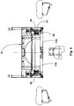
- the support frame corresponds to Outer contour of the bellows, d. H. essentially rectangular trained (Fig. 7).
- the housing 50 presents itself as a chamber-like, according to the contour of the bellows, recess formed in the Front side of the vehicle.
- the support frame 40 also has on his upper end further roles 42.
- the support frame 40 is by rolling 41, 42 stored in the housing 50.
- the rollers 41 rest on the floor 55 of the housing 50, however, the rollers 42 on the ceiling 56 of the Housing 50.
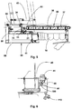
- the housing base 55 is through a false ceiling 58 covered, on which the link bridge 30 around a horizontal Axis 31 is pivotally mounted.
- This horizontal axis is part of a storage designated as 33, comprising a substantially L-shaped angle 34 that is transverse to the longitudinal axis of the vehicle extends over the intermediate floor 58 and one of them recorded bearing block 35, which is ultimately the inclusion of the horizontal axis 31 is used.
- the link bridge 30 (Fig. 5) consists of alternately arranged sliding and Tread members 37, 38, which are telescopically stored one inside the other such a link bridge is able to match the corresponding Movements, especially when cornering with each other to give way to connected vehicles. To cover the gap is between the link bridge and the floor 80 of the vehicle Bridge plate 81 provided.
- the Support frame 40 has a bar 45, corresponding to this bar 45 the housing has a circumferential strip 58, between which a seal 100 is arranged. That means that in the extended state of the support frame 40, d. H. in the condition of the support frame in which it is is at the front opening of the housing that The interior of the housing is sealed against contamination.
Abstract
Description
Die Erfindung betrifft einen Übergang zwischen zwei gelenkig miteinander verbundenen Fahrzeugen bzw. Fahrzeugteilen, insbesondere zwischen zwei gelenkig miteinander verbundenen Triebwagen, wobei der Übergang unter Bildung zweier miteinander kuppelbaren Übergangshälften teilbar ist, wobei jede einen Balg und eine Brücke umfassende Übergangshälfte durch ein im Fahrzeug bzw. Fahrzeugteil stirnseitig angeordnetes Gehäuse aufnehmbar ist, wobei dieses Gehäuse verschließbar ist.The invention relates to a transition between two articulated with each other connected vehicles or vehicle parts, in particular between two articulated railcar, the transition under Formation of two interlocking transition halves is divisible, wherein each transition half comprising a bellows and a bridge by an im Vehicle or vehicle part can be accommodated on the front side of the housing is, this housing is closable.
Triebwagenzüge sind bekannt; sie werden überwiegend im Nahbereichsverkehr eingesetzt und bestehen üblicherweise aus zwei Triebwagen und einem Mittelwagen. Bei hohem Fahrgastaufkommen kann es erforderlich sein, zwei derartige Züge miteinander zu kuppeln. Hierzu ist entweder bereits ein Übergang an der Stirnseite des Triebwagens vorgesehen, oder er wird nachträglich eingebaut. Die Bedienkonsole für den Triebwagen ist häufig seitlich zur stirnseitigen Öffnung des Triebwagens angeordnet. Railcar trains are known; they are mainly used in Local traffic is used and usually consists of two Railcars and an intermediate car. With high passenger volume can it may be necessary to couple two such trains together. This is either a transition at the front of the railcar provided, or it is installed later. The control console for the The railcar is often to the side of the front opening of the railcar arranged.
Aus der EP 608 455 ist allerdings ebenfalls bekannt, sowohl die Bedienkonsole als auch den Übergang in die stirnseitige Öffnung des Triebwagens wahlweise einzuschwenken.However, EP 608 455 also discloses both Control console and the transition into the front opening of the Rail car optionally swiveled in.
Aus der DE-A 11 088 253 ist ein Waggon mit stirnseitig angeordneter verschließbarer Türöffnung bekannt, wobei zu einer Seite der Türöffnung ein Türelement mit einem flexiblen Übergang vorgesehen ist, wobei der flexible Übergang einen Faltenbalg mit einer Übergangsbrücke umfaßt. Ein derartiger Waggon ist jedoch nicht geeignet, als Triebwagen eingesetzt zu werden, da die hierzu erforderliche Bedienkonsole fehlt.DE-A 11 088 253 describes a wagon with a front end closable door opening known, to one side of the door opening a door element with a flexible transition is provided, the flexible transition includes a bellows with a transition bridge. A such wagon is not suitable to be used as a railcar because the required control console is missing.
Die bekannte EP-A 167 766 zeigt ein Schienenfahrzeug, bei dem die Bedienkonsole in die stirnseitig angeordnete Öffnung einschwenkbar ist, jedoch bei seitlicher Stellung der Bedienkonsole in die nunmehr freie Türöffnung ein kompletter Übergang eingeschoben wird, der im nichtbenötigten Zustand im Wageninneren gelagert ist. Nachteilig hierbei ist, daß durch die Lagerung des kompletten Überganges im Wageninneren relativ viel Raum benötigt wird, der dann naturgemäß nicht mehr für den Transport von Personen zur Verfügung steht.The known EP-A 167 766 shows a rail vehicle in which the Control console can be swung into the opening on the front, however, with the control console in the side position in the now free position A complete transition is inserted into the door opening unused condition is stored inside the car. The disadvantage here is that by storing the entire transition inside the car relatively much space is required, which is then naturally no longer for the Transport of people is available.
Bei einer weiterhin bekannten Übergangseinrichtung gemäß der DE-A 1 220 463 ist bekannt, den Faltenbalg des Überganges bei Nichtgebrauch ebenfalls im Inneren des Fahrzeugs zu verstauen, wobei jedoch der Ort der Aufbewahrung auch wahlweise durch die Frontverkleidung, d. h. die Tür zum Verschließen der Wagenöffnung eingenommen werden kann, um auf diese Weise Raum zu sparen. Gleichwohl gilt aber auch bei dieser Übergangseinrichtung, daß im Innenraum des Fahrzeugs Platz verloren geht, der ansonsten für die Beförderung von Passagieren zur Verfügung stünde.In a further known transition device according to DE-A 1 220 463 is known, the bellows of the transition when not in use also stowed inside the vehicle, but the location of the Storage optionally also through the front panel, d. H. the door to close the car opening can be taken to this way saving space. Nevertheless, this also applies to this Transition device that space is lost in the interior of the vehicle, which would otherwise be available for the transportation of passengers.
Aus der US-A 846 740 ist eine Verbindung zwischen zwei miteinander kuppelbaren Lokomotiven durch einen Übergang bekannt. Die Übergangsbrücke des aus Balg und Brücke bestehenden Überganges wird hierbei durch ein Übergangsblech gebildet. Im Einzelnen ist hierbei vorgesehen, daß im nichtbenötigen Zustand des Überganges die einzelnen Übergangshälften in einem in der Stirnseite des Zuges angeordneten Gehäuse lagern, wobei die Gehäuseöffnung durch seitlich verschwenkbare Türelemente verschließbar ist. Der Balg der Übergangshälfte ist hierbei an der Rückwand des Gehäuses der Lokomotive angeordnet, so daß beim Auseinanderfahren des Balges der Balg immer noch die Tiefe des Gehäuses überbrücken muß, bevor er tatsächlich aus dem Fahrzeug herausgelangt, um dann mit dem Balg der anderen Übergangshälfte gekuppelt zu werden. Das heißt, daß aufgrund der Tiefe des Gehäuses der Balg relativ länger sein muß, um eben die Tiefe des Gehäuses zu überspannen, als dies an sich notwendig ist, wenn man davon ausgeht, daß der Balg an sich nur den lichten Raum zwischen zwei gelenkig miteinander verbundenen Fahrzeugen bzw. Fahrzeugteilen überspannen soll.From US-A 846 740 there is a connection between two detachable locomotives known by a transition. The Transition bridge of the transition consisting of bellows and bridge here formed by a transition plate. In detail here is provided that the individual in the unnecessary state of the transition Transition halves arranged in one in the front of the train Store the housing, the housing opening being pivoted laterally Door elements can be locked. The bellows of the transition half is on the rear wall of the housing of the locomotive arranged so that when Spread the bellows the bellows still the depth of the housing bridge before it actually gets out of the vehicle, to be coupled with the bellows of the other half of the transition. This means that due to the depth of the housing, the bellows will be relatively longer must, in order to span the depth of the housing, than this in itself is necessary if one assumes that the bellows per se only clear space between two articulated vehicles or vehicle parts.
Der Erfindung liegt daher die Aufgabe zugrunde, einen Übergang der eingangs genannten Art derart weiter zu entwickeln, daß der Balg nur die absolut notwendige Länge zum Überbrücken des lichten Raumes zwischen zwei Fahrzeugen bzw. Fahrzeugenteilen aufweist.The invention is therefore based on the object of a transition type mentioned at the beginning to develop such that the bellows only the absolutely necessary length to bridge the clear space between has two vehicles or vehicle parts.
Die Aufgabe wird erfindungsgemäß dadurch gelöst, daß der Balg der Übergangshälfte einen Tragrahmen aufweist, der im Gehäuse verschieblich gelagert ist. Durch die Verschiebung des Tragrahmens und damit des Balges an den stirnseiten Rand des Gehäuses wird erreicht, daß der Balg nur genauso lang wie der Abstand bzw. der halbe Abstand zwischen zwei Fahrzeugen sein muß. Aufgrund des kürzeren Balges kann der Übergang preiswerter hergestellt werden. Die Kontur des Tragrahmens entspricht der des Balges, das heißt, der Tragrahmen weist die Form eines geschlossenen Rechteckprofils auf.The object is achieved in that the bellows Transitional half has a support frame that is slidable in the housing is stored. By moving the support frame and thus the Bellows on the front edge of the housing is achieved that the bellows only as long as the distance or half the distance between two Vehicles must be. Due to the shorter bellows, the transition can can be manufactured more cheaply. The contour of the support frame corresponds to des Bellows, that is, the support frame has the shape of a closed Rectangular profile.
Nach einem vorteilhaften Merkmal der Erfindung ist vorgesehen, daß der Tragrahmen Rollen aufweist, um eine leichte Verschiebung des Balges der Übergangshälfte im Gehäuse, das heißt, auf dem Boden des Gehäuses, zu ermöglichen. According to an advantageous feature of the invention it is provided that the Carrier frame has rollers to slightly shift the bellows Transitional half in the housing, that is, on the bottom of the housing enable.
Um weiterhin sicherzustellen, daß im ausgefahrenen Zustand des Tragrahmens, d. h. in dem Zustand, in dem der Tragrahmen sich unmittelbar an der Gehäuseöffnung befindet, der Tragrahmen in dieser Stellung verbleibt, sind Stützmittel vorgesehen, durch die der Tragrahmen gegenüber dem Gehäuse abstützbar gelagert ist. Im Einzelnen kann ein solches Stützmittel als Gelenkhebel oder auch als Kolben-Zylinderantrieb ausgebildet sein.To further ensure that when the Support frame, d. H. in the state in which the support frame is the support frame is located directly at the housing opening Position remains, support means are provided through which the support frame is supported against the housing. In particular, one such support means as an articulated lever or as a piston-cylinder drive be trained.
Nach einem weiteren besonderen Merkmal der Erfindung ist das Gehäuse durch den Tragrahmen im ausgefahrenen Zustand der Übergangshälfte bzw. des Balges abdichtbar. Hierdurch wird verhindert, daß im gekuppelten Zustand zweier Fahrzeuge Verunreinigungen in das den Balg aufnehmende Gehäuse eintreten können. Wird der Übergang bzw. die Übergangshälfte des Triebwagens nicht benötigt, dann kann naturgemäß kein Schmutz in das Gehäuse eindringen, da dann das Gehäuse insbesondere durch Türen verschließbar ist. Um im einzelnen eine Abdichtung des Gehäuses zu ermöglichen, weist der Tragrahmen eine umlaufende Leiste auf, die im ausgefahrenen Zustand der Übergangshälfte mit einer am Gehäuse korrespondierend zu der Leiste des Tragrahmens angeordneten umlaufenden Leiste abdichtend zusammenwirkt, wobei vorteilhaft zwischen den Leisten eine Dichtung angeordnet ist.According to another special feature of the invention is the housing through the support frame in the extended state of the transition half or of the bellows sealable. This prevents the coupled Condition of two vehicles soiling in the bellows receiving Housing can enter. If the transition or the transition half of the railcar is not required, then naturally no dirt can get in penetrate the housing, since then the housing in particular through doors is lockable. In order to seal the housing in detail enable, the support frame has a circumferential bar, which in extended state of the transition half with one on the housing arranged corresponding to the bar of the support frame circumferential strip cooperates sealingly, advantageously between a seal is arranged on the strips.
Weiterhin ist vorgesehen, daß der Balg der Übergangshälfte einen Kuppelrahmen zur Kupplung mit dem Balg der anderen Übergangshälfte aufweist. Zum Verstauen der Gliederbrücke besitzt die Gliederbrücke eine vertikal verlaufende Achse, um die die Gliederbrücke nach oben in das Gehäuse einklappbar ist.It is also provided that the bellows of the transition half Dome frame for coupling with the bellows of the other transition half having. To store the link bridge, the link bridge has one vertical axis around which the sectional bridge moves upwards into the Housing is collapsible.
Anhand der Zeichnungen wird die Erfindung nachstehend beispielhaft näher erläutert.
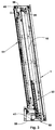
Figur 1- zeigt die Übergangshälfte in einer Seitenansicht im ausgefahrenen Zustand;
- Figur 2
- zeigt eine Draufsicht auf die Übergangshälfte gemäß Fig. 1;
- Figur 3
- zeigt eine Seitenansicht auf die Übergangshälfte gemäß Fig. 1, wobei sich jedoch die Übergangshälfte im Gehäuse befindet;
- Figur 4
- zeigt eine Draufsicht auf die Übergangshälfte gemäß Fig. 3;
- Figur 5
- zeigt die Einzelheit V aus Fig. 1 in vergrößerter Darstellung;
- Figur 6
- zeigt die Einzelheit VI aus Fig. 2 in vergrößerter Darstellung;
- Figur 7
- zeigt eine Frontansicht auf die Übergangshälfte bei geöffneten Türen.
- Figure 1
- shows the transition half in a side view in the extended state;
- Figure 2
- shows a plan view of the transition half of FIG. 1;
- Figure 3
- shows a side view of the transition half of Figure 1, but the transition half is in the housing.
- Figure 4
- shows a plan view of the transition half of FIG. 3;
- Figure 5
- shows the detail V of Figure 1 in an enlarged view.
- Figure 6
- shows the detail VI of Figure 2 in an enlarged view.
- Figure 7
- shows a front view of the transition half with the doors open.
Gemäß den Figuren 1 bis 4 zeigt die insgesamt mit 1 bezeichnete
Übergangshälfte den Balg 10 und den stirnseitig am Balg angeordneten
Kuppelrahmen 20. Die Übergangshälfte 1 besitzt darüber hinaus die
Gliederbrücke 30. Der Balg 10 ist an dem mit 40 bezeichneten Tragrahmen
angelenkt, der im insgesamt mit 50 bezeichneten Gehäuse auf Rollen 41
verschieblich gelagert ist. Der Tragrahmen ist korrespondierend zur
Außenkontur des Balges, d. h. im Wesentlichen umlaufend rechteckförmig
ausgebildet (Fig. 7). Das Gehäuse 50 stellt sich als kammerartige,
entsprechend der Kontur des Balges, ausgebildete Ausnehmung in der
Stirnseite des Fahrzeuges dar. Um ein Verkanten des Tragrahmens 40 im
Gehäuse 50 zu vermeiden, besitzt der Tragrahmen 40 auch an seinem
oberen Ende weitere Rollen 42. Im ausgefahrenen Zustand des
Tragrahmens 40 wird dieser durch den Gelenkhebel 43 gegenüber dem
Gehäuse 50 abgestützt. Insbesondere sind vier solche Gelenkhebel 43
vorgesehen, die sich umfangsverteilt am Tragrahmen 40 anordnen. Zur
Abdeckung des Abstandes zwischen Tragrahmen 40 und
Gehäuserückwand 51 ist im Seitenwandbereich eine sich ähnlich einem
Faltenbalg zusammenschiebende Abdeckung 70 vorgesehen. Verschließbar
ist das Gehäuse durch die beiden Türflügel 110 (Fig. 7). According to FIGS. 1 to 4, the one designated as a
Wie bereits an andere Stelle ausgeführt, ist der Tragrahmen 40 durch Rollen
41, 42 im Gehäuse 50 gelagert. Hierbei lagern die Rollen 41 auf dem Boden
55 des Gehäuses 50, hingegen die Rollen 42 an der Decke 56 des
Gehäuses 50. Der Gehäuseboden 55 ist durch eine Zwischendecke 58
abgedeckt, auf der die Gliederbrücke 30 um eine horizontal verlaufende
Achse 31 verschwenkbar gelagert ist. Diese horizontal verlaufende Achse
ist Bestandteil einer insgesamt mit 33 bezeichneten Lagerung, umfassend
einen im Wesentlichen L-förmigen Winkel 34, der sich quer zur Längsachse
des Fahrzeuges über den Zwischenboden 58 erstreckt und einen davon
aufgenommenen Lagerbock 35, der schlußendlich der Aufnahme der
horizontal verlaufenden Achse 31 dient.As stated elsewhere, the
Die Gliederbrücke 30 (Fig. 5) besteht aus abwechselnd angeordneten Gleit- und
Trittgliedern 37, 38, die teleskopartig ineinander gelagert sind, damit
eine solche Gliederbrücke in der Lage ist, den entsprechenden
Fahrbewegungen, insbesondere bei Kurvenfahrt der gelenkig miteinander
verbundenen Fahrzeuge nachgeben zu können. Zur Abdeckung des Spaltes
zwischen Gliederbrücke und dem Boden 80 des Fahrzeugs ist ein
Brückenblech 81 vorgesehen.The link bridge 30 (Fig. 5) consists of alternately arranged sliding and
Zur Abdichtung des Gehäuses 50 (Fig. 6) im ausgefahrenen Zustand der
Übergangshälfte bzw. im ausgefahrenen Zustand des Balges 10 zeigt der
Tragrahmen 40 eine Leiste 45, wobei korrespondierend zu dieser Leiste 45
das Gehäuse eine ebenfalls umlaufende Leiste 58 besitzt, zwischen denen
eine Dichtung 100 angeordnet. Das heißt, daß im ausgefahrenen Zustand
des Tragrahmens 40, d. h. in dem Zustand des Tragrahmens, in dem dieser
sich an der stirnseitigen Öffnung des Gehäuses befindet, das
Gehäuseinnere gegenüber Verschmutzung abgedichtet ist.To seal the housing 50 (Fig. 6) in the extended state of the
Transition half or in the extended state of the
Claims (11)
dadurch gekennzeichnet,
daß der Balg (10) der Übergangshälfte (1) einen Tragrahmen (40) aufweist, der im Gehäuse (50) verschieblich gelagert ist.Transition between two articulated vehicles or vehicle parts, in particular railcars connected to one another, the transition being separable to form two coupling halves (1) which can be coupled to one another, each with a transition half (1) comprising a bellows (10) and a bridge (30) a housing (50) arranged at the end in the vehicle or vehicle part can be accommodated, this housing (50) being closable,
characterized,
that the bellows (10) of the transition half (1) has a support frame (40) which is slidably mounted in the housing (50).
dadurch gekennzeichnet,
daß der Tragrahmen (40) Rollen (41, 42) aufweist.Transition according to claim 1,
characterized,
that the support frame (40) has rollers (41, 42).
dadurch gekennzeichnet,
daß der Tragrahmen (40) gegenüber dem Gehäuse (50) durch Stützmittel abstützbar gelagert ist.Transition according to one of the preceding claims,
characterized,
that the support frame (40) relative to the housing (50) is supported by support means.
dadurch gekennzeichnet,
daß das Stützmittel als Gelenkhebel (43) ausgebildet ist.Transition according to claim 3,
characterized,
that the support means is designed as an articulated lever (43).
dadurch gekennzeichnet,
daß das Stützmittel als Kolben-Zylinderantrieb ausgebildet ist. Transition according to claim 3,
characterized,
that the support means is designed as a piston-cylinder drive.
dadurch gekennzeichnet,
daß durch den Tragrahmen (40) das Gehäuse (50) im ausgefahrenen Zustand der Übergangshälfte (1) abdichtbar ist.Transition according to one of the preceding claims,
characterized,
that the housing (50) can be sealed by the support frame (40) in the extended state of the transition half (1).
dadurch gekennzeichnet,
daß der Tragrahmen (40) eine umlaufende Leiste (45) aufweist, die im ausgefahrenen Zustand der Übergangshälfte mit einer am Gehäuse (50) angeordneten umlaufenden Leiste (58) des Gehäuses (50) abdichtend zusammenwirkt.Transition according to claim 6,
characterized,
that the support frame (40) has a circumferential bar (45) which, in the extended state of the transition half, cooperates sealingly with a circumferential bar (58) of the housing (50) arranged on the housing (50).
dadurch gekennzeichnet,
daß zwischen den beiden Leisten (45, 58) eine Dichtung (100) angeordnet ist.Transition according to claim 7,
characterized,
that a seal (100) is arranged between the two strips (45, 58).
dadurch gekennzeichnet,
daß der Balg (10) der Übergangshälfte (1) einen Kuppelrahmen (20) zur Kupplung mit dem Balg der anderen Übergangshälfte aufweist.Transition according to one of the preceding claims,
characterized,
that the bellows (10) of the transition half (1) has a coupling frame (20) for coupling with the bellows of the other transition half.
dadurch gekennzeichnet,
daß die Gliederbrücke (30) um eine horizontal verlaufende Achse (31) in das Gehäuse (50) einklappbar ist.Transition according to claim 9,
characterized,
that the link bridge (30) can be folded into the housing (50) about a horizontally extending axis (31).
dadurch gekennzeichnet,
daß der Balg (10) als Wellen- oder Faltenbalg ausgebildet ist.Transition according to one of the preceding claims,
characterized,
that the bellows (10) is designed as a bellows or bellows.
Priority Applications (2)
| Application Number | Priority Date | Filing Date | Title |
|---|---|---|---|
| EP19980108969 EP0958981B1 (en) | 1998-05-16 | 1998-05-16 | Two vehicles or vehicle parts flexibly connected to each other, especially between two motor cars flexibly connected to each other, with an inter-communication diaphram. |
| DE59805506T DE59805506D1 (en) | 1998-05-16 | 1998-05-16 | Two articulated vehicles or vehicle parts, in particular between two articulated railcars, with a transition. |
Applications Claiming Priority (1)
| Application Number | Priority Date | Filing Date | Title |
|---|---|---|---|
| EP19980108969 EP0958981B1 (en) | 1998-05-16 | 1998-05-16 | Two vehicles or vehicle parts flexibly connected to each other, especially between two motor cars flexibly connected to each other, with an inter-communication diaphram. |
Publications (2)
| Publication Number | Publication Date |
|---|---|
| EP0958981A1 true EP0958981A1 (en) | 1999-11-24 |
| EP0958981B1 EP0958981B1 (en) | 2002-09-11 |
Family
ID=8231949
Family Applications (1)
| Application Number | Title | Priority Date | Filing Date |
|---|---|---|---|
| EP19980108969 Expired - Lifetime EP0958981B1 (en) | 1998-05-16 | 1998-05-16 | Two vehicles or vehicle parts flexibly connected to each other, especially between two motor cars flexibly connected to each other, with an inter-communication diaphram. |
Country Status (2)
| Country | Link |
|---|---|
| EP (1) | EP0958981B1 (en) |
| DE (1) | DE59805506D1 (en) |
Cited By (3)
| Publication number | Priority date | Publication date | Assignee | Title |
|---|---|---|---|---|
| EP1580094A1 (en) * | 2004-03-24 | 2005-09-28 | HÜBNER GmbH | Bellow of a gangway between the carbodies of two articulated vehicles, comprising a frame for absorbing shocks. |
| CN102476641A (en) * | 2010-11-26 | 2012-05-30 | 许布奈有限公司 | Bridge for the intersection of two vehicles with a jointed connection |
| WO2013182221A1 (en) * | 2012-06-04 | 2013-12-12 | Siemens Ag Österreich | Wagon connection for a rail vehicle |
Families Citing this family (3)
| Publication number | Priority date | Publication date | Assignee | Title |
|---|---|---|---|---|
| ES2376181T3 (en) | 2009-04-02 | 2012-03-09 | Hübner GmbH | INTERCOM COMMUNICATION FUEL OF A FRONT STEP BETWEEN TWO VEHICLES? CONNECTED CULTS ARTICULATED BETWEEN THEM |
| CN102180177B (en) * | 2011-01-26 | 2014-05-07 | 常州虎伯拉今创交通设备有限公司 | Run-through channel for high-speed rail passenger vehicle |
| PL2700553T3 (en) | 2012-08-22 | 2015-02-27 | Huebner Gmbh & Co Kg | Passage with a bridge and a tunnel-shaped enveloping bellows between two vehicles joined through an articulated connection |
Citations (8)
| Publication number | Priority date | Publication date | Assignee | Title |
|---|---|---|---|---|
| US846740A (en) | 1906-08-27 | 1907-03-12 | Milton Forder | Wrench. |
| DE1088253B (en) | 1957-03-26 | 1960-09-01 | Bayer Ag | Method for determining the vulcanization state of vulcanization mixtures of natural and synthetic rubber by measuring mechanical properties and device for practicing the method |
| DE1220463B (en) | 1962-08-03 | 1966-07-07 | Kloeckner Humboldt Deutz Ag | Transition device on the streamlined head of rail powered rail cars and control cars |
| US3486464A (en) * | 1968-01-29 | 1969-12-30 | Budd Co | Retractable and extensible railway car diaphragm |
| EP0167766A2 (en) | 1984-06-30 | 1986-01-15 | Duewag Aktiengesellschaft | Vehicle, especially a rail vehicle |
| EP0504458A1 (en) * | 1991-03-21 | 1992-09-23 | HÜBNER Gummi- und Kunststoff GmbH | Communication passage between two vehicles, especially railway vehicles |
| EP0608455A1 (en) | 1993-01-28 | 1994-08-03 | HÜBNER Gummi- und Kunststoff GmbH | Rail coach with closeable dooropening on its face |
| DE9410551U1 (en) * | 1994-06-30 | 1994-09-08 | Ammendorf Waggonbau | Front wall transition of a train with streamlined power car and / or control car |
-
1998
- 1998-05-16 DE DE59805506T patent/DE59805506D1/en not_active Expired - Lifetime
- 1998-05-16 EP EP19980108969 patent/EP0958981B1/en not_active Expired - Lifetime
Patent Citations (8)
| Publication number | Priority date | Publication date | Assignee | Title |
|---|---|---|---|---|
| US846740A (en) | 1906-08-27 | 1907-03-12 | Milton Forder | Wrench. |
| DE1088253B (en) | 1957-03-26 | 1960-09-01 | Bayer Ag | Method for determining the vulcanization state of vulcanization mixtures of natural and synthetic rubber by measuring mechanical properties and device for practicing the method |
| DE1220463B (en) | 1962-08-03 | 1966-07-07 | Kloeckner Humboldt Deutz Ag | Transition device on the streamlined head of rail powered rail cars and control cars |
| US3486464A (en) * | 1968-01-29 | 1969-12-30 | Budd Co | Retractable and extensible railway car diaphragm |
| EP0167766A2 (en) | 1984-06-30 | 1986-01-15 | Duewag Aktiengesellschaft | Vehicle, especially a rail vehicle |
| EP0504458A1 (en) * | 1991-03-21 | 1992-09-23 | HÜBNER Gummi- und Kunststoff GmbH | Communication passage between two vehicles, especially railway vehicles |
| EP0608455A1 (en) | 1993-01-28 | 1994-08-03 | HÜBNER Gummi- und Kunststoff GmbH | Rail coach with closeable dooropening on its face |
| DE9410551U1 (en) * | 1994-06-30 | 1994-09-08 | Ammendorf Waggonbau | Front wall transition of a train with streamlined power car and / or control car |
Cited By (4)
| Publication number | Priority date | Publication date | Assignee | Title |
|---|---|---|---|---|
| EP1580094A1 (en) * | 2004-03-24 | 2005-09-28 | HÜBNER GmbH | Bellow of a gangway between the carbodies of two articulated vehicles, comprising a frame for absorbing shocks. |
| CN102476641A (en) * | 2010-11-26 | 2012-05-30 | 许布奈有限公司 | Bridge for the intersection of two vehicles with a jointed connection |
| CN102476641B (en) * | 2010-11-26 | 2014-09-10 | 许布奈有限公司 | Bridge for the intersection of two vehicles with a jointed connection |
| WO2013182221A1 (en) * | 2012-06-04 | 2013-12-12 | Siemens Ag Österreich | Wagon connection for a rail vehicle |
Also Published As
| Publication number | Publication date |
|---|---|
| EP0958981B1 (en) | 2002-09-11 |
| DE59805506D1 (en) | 2002-10-17 |
Similar Documents
| Publication | Publication Date | Title |
|---|---|---|
| DE2757201C2 (en) | Transition device between vehicles, in particular railway vehicles | |
| DE2739415C2 (en) | Sleeping facilities in long-haul cabs for trucks with built-in caravans | |
| EP1864833B1 (en) | Articulated vehicle composed of several coupled vehicle sections | |
| DE4020020A1 (en) | RAILWAY TROLLEY FOR TRANSPORTING PASSENGER VEHICLES | |
| EP0958981B1 (en) | Two vehicles or vehicle parts flexibly connected to each other, especially between two motor cars flexibly connected to each other, with an inter-communication diaphram. | |
| DE1220463B (en) | Transition device on the streamlined head of rail powered rail cars and control cars | |
| EP0608455B1 (en) | Rail coach with closeable dooropening on its face | |
| AT518631B1 (en) | articulated vehicle | |
| EP0854813B1 (en) | Communication point between two vehicles flexibly connected to each other, e.g. railway coaches or underground coaches | |
| DE19824404A1 (en) | Vehicle with at least one sliding side door | |
| DE19503081A1 (en) | Rail car with passenger crossover for inner, trailer or driving unit | |
| DE4317013B4 (en) | Multi-purpose railway carriages | |
| DE102013102698A1 (en) | Multi-part rail vehicle | |
| EP0061680A1 (en) | Articulated-vehicle arrangement with a totally enclosed articulation space | |
| EP3838668A1 (en) | Mobile enclosed space | |
| DE102017115542B4 (en) | rail vehicle association | |
| DE7033588U (en) | CARAVAN TRAILER. | |
| DE1168945B (en) | Articulated connection of a rail or road articulated vehicle | |
| AT394170B (en) | PRESSURE-TIGHT TRANSITION FITTING FIXED TO A CAR BOX END OF A RAIL VEHICLE | |
| DE4235612A1 (en) | Two part railway goods car - each part is formed as track vehicle with wheel units and impact bumper plates on ends and has loading surfaces spaced apart so as not to touch | |
| EP0612637A1 (en) | Sliding door for driving cab of a truck | |
| DE69905523T2 (en) | Arrangement of a road vehicle cab | |
| WO1993008061A1 (en) | Flexible weatherproof gangway between two goods-wagon units with height-adjustable roofs | |
| EP3812234B1 (en) | Passenger transport vehicle and step device for a passenger transport vehicle | |
| AT413684B (en) | REPLACEMENT BY FRONT TRANSITION |
Legal Events
| Date | Code | Title | Description |
|---|---|---|---|
| PUAI | Public reference made under article 153(3) epc to a published international application that has entered the european phase |
Free format text: ORIGINAL CODE: 0009012 |
|
| AK | Designated contracting states |
Kind code of ref document: A1 Designated state(s): DE ES FR GB IT |
|
| AX | Request for extension of the european patent |
Free format text: AL;LT;LV;MK;RO;SI |
|
| 17P | Request for examination filed |
Effective date: 19991018 |
|
| AKX | Designation fees paid |
Free format text: DE ES FR GB IT |
|
| 17Q | First examination report despatched |
Effective date: 20001019 |
|
| GRAG | Despatch of communication of intention to grant |
Free format text: ORIGINAL CODE: EPIDOS AGRA |
|
| RTI1 | Title (correction) |
Free format text: TWO VEHICLES OR VEHICLE PARTS FLEXIBLY CONNECTED TO EACH OTHER, ESPECIALLY BETWEEN TWO MOTOR CARS FLEXIBLY CONNECTED TO EACH OTHER, WITH AN INTER-COMMUNICATION DIAPHRAM. |
|
| RTI1 | Title (correction) |
Free format text: TWO VEHICLES OR VEHICLE PARTS FLEXIBLY CONNECTED TO EACH OTHER, ESPECIALLY BETWEEN TWO MOTOR CARS FLEXIBLY CONNECTED TO EACH OTHER, WITH AN INTER-COMMUNICATION DIAPHRAM. |
|
| GRAG | Despatch of communication of intention to grant |
Free format text: ORIGINAL CODE: EPIDOS AGRA |
|
| GRAG | Despatch of communication of intention to grant |
Free format text: ORIGINAL CODE: EPIDOS AGRA |
|
| GRAH | Despatch of communication of intention to grant a patent |
Free format text: ORIGINAL CODE: EPIDOS IGRA |
|
| GRAH | Despatch of communication of intention to grant a patent |
Free format text: ORIGINAL CODE: EPIDOS IGRA |
|
| GRAA | (expected) grant |
Free format text: ORIGINAL CODE: 0009210 |
|
| AK | Designated contracting states |
Kind code of ref document: B1 Designated state(s): DE ES FR GB IT |
|
| PG25 | Lapsed in a contracting state [announced via postgrant information from national office to epo] |
Ref country code: IT Free format text: LAPSE BECAUSE OF FAILURE TO SUBMIT A TRANSLATION OF THE DESCRIPTION OR TO PAY THE FEE WITHIN THE PRESCRIBED TIME-LIMIT;WARNING: LAPSES OF ITALIAN PATENTS WITH EFFECTIVE DATE BEFORE 2007 MAY HAVE OCCURRED AT ANY TIME BEFORE 2007. THE CORRECT EFFECTIVE DATE MAY BE DIFFERENT FROM THE ONE RECORDED. Effective date: 20020911 Ref country code: FR Free format text: LAPSE BECAUSE OF NON-PAYMENT OF DUE FEES Effective date: 20020911 |
|
| REG | Reference to a national code |
Ref country code: GB Ref legal event code: FG4D Free format text: NOT ENGLISH |
|
| GBT | Gb: translation of ep patent filed (gb section 77(6)(a)/1977) |
Effective date: 20020911 |
|
| REF | Corresponds to: |
Ref document number: 59805506 Country of ref document: DE Date of ref document: 20021017 |
|
| PG25 | Lapsed in a contracting state [announced via postgrant information from national office to epo] |
Ref country code: ES Free format text: LAPSE BECAUSE OF FAILURE TO SUBMIT A TRANSLATION OF THE DESCRIPTION OR TO PAY THE FEE WITHIN THE PRESCRIBED TIME-LIMIT Effective date: 20030328 |
|
| EN | Fr: translation not filed | ||
| PLBE | No opposition filed within time limit |
Free format text: ORIGINAL CODE: 0009261 |
|
| STAA | Information on the status of an ep patent application or granted ep patent |
Free format text: STATUS: NO OPPOSITION FILED WITHIN TIME LIMIT |
|
| 26N | No opposition filed |
Effective date: 20030612 |
|
| PGFP | Annual fee paid to national office [announced via postgrant information from national office to epo] |
Ref country code: DE Payment date: 20160324 Year of fee payment: 19 Ref country code: GB Payment date: 20160520 Year of fee payment: 19 |
|
| REG | Reference to a national code |
Ref country code: DE Ref legal event code: R119 Ref document number: 59805506 Country of ref document: DE |
|
| GBPC | Gb: european patent ceased through non-payment of renewal fee |
Effective date: 20170516 |
|
| PG25 | Lapsed in a contracting state [announced via postgrant information from national office to epo] |
Ref country code: DE Free format text: LAPSE BECAUSE OF NON-PAYMENT OF DUE FEES Effective date: 20171201 Ref country code: GB Free format text: LAPSE BECAUSE OF NON-PAYMENT OF DUE FEES Effective date: 20170516 |