EP0958957B1 - Vorrichtung zur Halterung eines Fahrzeugsitzes - Google Patents
Vorrichtung zur Halterung eines Fahrzeugsitzes Download PDFInfo
- Publication number
- EP0958957B1 EP0958957B1 EP99109112A EP99109112A EP0958957B1 EP 0958957 B1 EP0958957 B1 EP 0958957B1 EP 99109112 A EP99109112 A EP 99109112A EP 99109112 A EP99109112 A EP 99109112A EP 0958957 B1 EP0958957 B1 EP 0958957B1
- Authority
- EP
- European Patent Office
- Prior art keywords
- retaining members
- seat
- vehicle floor
- expanding part
- manner
- Prior art date
- Legal status (The legal status is an assumption and is not a legal conclusion. Google has not performed a legal analysis and makes no representation as to the accuracy of the status listed.)
- Expired - Lifetime
Links
- 230000009471 action Effects 0.000 claims description 2
- 230000003993 interaction Effects 0.000 claims description 2
- 241000826860 Trapezium Species 0.000 claims 1
- 230000007480 spreading Effects 0.000 description 7
- 238000003892 spreading Methods 0.000 description 7
- 230000008901 benefit Effects 0.000 description 2
- 210000000078 claw Anatomy 0.000 description 2
- 230000000694 effects Effects 0.000 description 2
- 238000003780 insertion Methods 0.000 description 2
- 230000037431 insertion Effects 0.000 description 2
- 238000000034 method Methods 0.000 description 2
- 230000008569 process Effects 0.000 description 2
- 238000004873 anchoring Methods 0.000 description 1
- 238000010276 construction Methods 0.000 description 1
- 230000009760 functional impairment Effects 0.000 description 1
- 238000005304 joining Methods 0.000 description 1
- 238000004519 manufacturing process Methods 0.000 description 1
Images
Classifications
-
- F—MECHANICAL ENGINEERING; LIGHTING; HEATING; WEAPONS; BLASTING
- F16—ENGINEERING ELEMENTS AND UNITS; GENERAL MEASURES FOR PRODUCING AND MAINTAINING EFFECTIVE FUNCTIONING OF MACHINES OR INSTALLATIONS; THERMAL INSULATION IN GENERAL
- F16B—DEVICES FOR FASTENING OR SECURING CONSTRUCTIONAL ELEMENTS OR MACHINE PARTS TOGETHER, e.g. NAILS, BOLTS, CIRCLIPS, CLAMPS, CLIPS OR WEDGES; JOINTS OR JOINTING
- F16B21/00—Means for preventing relative axial movement of a pin, spigot, shaft or the like and a member surrounding it; Stud-and-socket releasable fastenings
- F16B21/06—Releasable fastening devices with snap-action
- F16B21/065—Releasable fastening devices with snap-action with an additional locking element
-
- B—PERFORMING OPERATIONS; TRANSPORTING
- B60—VEHICLES IN GENERAL
- B60N—SEATS SPECIALLY ADAPTED FOR VEHICLES; VEHICLE PASSENGER ACCOMMODATION NOT OTHERWISE PROVIDED FOR
- B60N2/00—Seats specially adapted for vehicles; Arrangement or mounting of seats in vehicles
- B60N2/005—Arrangement or mounting of seats in vehicles, e.g. dismountable auxiliary seats
- B60N2/015—Attaching seats directly to vehicle chassis
- B60N2/01508—Attaching seats directly to vehicle chassis using quick release attachments
- B60N2/01516—Attaching seats directly to vehicle chassis using quick release attachments with locking mechanisms
- B60N2/01525—Attaching seats directly to vehicle chassis using quick release attachments with locking mechanisms with locking elements expanding inside or under the vehicle floor or rail
Definitions
- the present invention relates to a mounting device for a vehicle seat detachable mounting of the vehicle seat on a vehicle floor, with at least two Seat-side holding members for interaction with the bottom-side, in particular stationary mounting elements, the holding members in a locked state in a form-fitting connection with the mounting elements and between the holding members a tapering towards the vehicle floor Spreading part is arranged, by its relative movement to the holding members Holding members from an unspread release state, in which they with the Bracket elements can be coupled and separated from them, in a spread Locked state are convertible.
- brackets have the disadvantage in part that the entire seat for Loosen or insert moves in a certain way, especially tilted must become. This is particularly disadvantageous for heavy seats (benches).
- a holder of the type described at the outset is known from of the two parts pivotably attached to a seat foot, each provided with a groove (a bolt part and a claw part) one in front and one in a locking position can reach behind the bolt part fastened to the vehicle floor, whereby the grooves, the locking parts and concave sections of the seat base with each other form a positive connection.
- This known device does Advantage that the joining direction between the seat and the vehicle is essentially vertical to the vehicle floor, which is a simple longitudinal movement without any tilting of the seat.
- the known device has the Disadvantage that it is relatively expensive to construct, because of a necessary fairly precise adherence to assembly tolerances for the pin connections rotatable attachment of the moving parts, a required spring element and the precisely coordinated contour of the bolt part, Claw part and seat foot.
- the present invention has for its object a device Generic type to create, which is characterized by structural simplicity as well high ease of use.
- the holding members are in one Have direction tapering towards the vehicle floor head section whose end on the seat side faces away from each other on the outside Holding links are grooves, which in the locked state with contact surfaces that the Are facing the seat, the positive connection with the bracket elements form, and the holding members on mutually facing inner sides towards the Vehicle floor converging towards the tapered contour of the Spreading part adapted inclined surfaces as contact and sliding surfaces for the expansion part have, such that the holding members under a wedge action of the expansion part linear lateral, essentially parallel to the vehicle floor Carry out translation movement.
- the mounting device according to the invention is extremely simple in construction educated.
- the expansion part can advantageously be a vertical one for locking the seat Carry out movement on the vehicle floor, thereby the direction of the seat bracket corresponds to the direction of actuation of the expansion part. It is from special advantage that this movement is only a linear, for Vehicle floor is essentially vertical movement.
- the holding links need only linear, parallel to the vehicle floor Carry out movements. This makes complicated and complex movements, especially tilting movements, the entire seat avoided, which is especially the case heavy seats (benches) is particularly advantageous.
- the mounting device according to the invention is advantageously used only for Locking the seat.
- the load-bearing capacity or load support can preferably be via separate support parts (seat feet) can be guaranteed.
- the invention Bracket device but can be advantageously integrated into a seat base.
- one can also advantageously move the expansion part Remote control via a suitable control device, such as a Bowden cable, a linkage, a hydraulic device, etc. may be provided.
- the fixed mounting elements can advantageously by edges of a optionally edge-reinforced opening in the vehicle floor, which is in the locked state be gripped by the holding members.
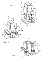
- 1 to 3 in Schematic perspective view of an embodiment of an inventive Holding device, namely in the release state, in an intermediate state and in the locked state.
- a device for releasably holding a vehicle seat a vehicle floor 1 (the seat is not shown; the vehicle floor 1 is in the Drawing indicated by a frame part) consists of at least two seat-side Holding members 2, which interact with the bottom, in particular stationary Bracket elements 3 are determined.
- the stationary mounting elements 3 are through formed at least two edges of an opening 4 in the vehicle floor 1, which in Locking state can be engaged by the holding members 2. Kick this way the holding members 2 in the locked state in a positive connection with the Brackets 3.
- the Vehicle floor 1 tapering expansion part 5 by its movement in the direction A on the vehicle floor 1 towards the holding members 2 from an unexpanded release state (Fig. 1), in which they can be coupled to the holding elements 3 or by these are separable, via intermediate states - as shown in Fig. 2 - into a spread Locking state (Fig. 3) can be transferred. Since the expansion part 5 has a wedge effect on the Exercises holding members 2, they perform a lateral, advantageously linear, in essentially (translational) movement directed parallel to the vehicle floor 1.
- the holding members 2 have a tapering in the direction A towards the vehicle floor 1 Head section 6, at the end of the seat facing each other facing away from the outside of the holding members 2 grooves 7, which are in the locked state with contact surfaces 8, which face the seat, the positive connection form with the support elements 3.
- the tapered Head section 6 facilitates the insertion of the holding members 2 into the bottom opening 4, where self-centering advantageously takes place during insertion. This is where particularly clear that the manufacturing tolerances to be observed of the different Parts of the device according to the invention are large in relation to those of the known Devices can be selected without associated functional impairment would be feared.
- the holding members 2 point in the direction A. towards the vehicle floor 1 towards the tapering contour of the expansion part 5 adapted inclined surfaces 9, which as contact and sliding surfaces for serve the expansion part 5.
- the expansion part 5 has at its tip an expansion section 10 which in the shown embodiment is formed as a straight prism, the Prism each have a base and top surface in the form of an isosceles trapezoid has a shorter base line facing the vehicle floor 1.
- the Spreading section 10 could also be formed in the shape of a truncated pyramid; on the However, the manner shown is advantageously distributed by the expansion part 5 spreading forces exerted on the holding members 2 over a larger effective area, so that relatively lower surface pressures arise.
- the expansion section 10 is followed by a guide section 11, which in its Basic shape is prismatic, in particular as a cuboid.
- a broken line indicates the position of the separating surface between the expansion section 10 and the guide section 11.
- the guide section 11 of the expansion part 5 is during the anchoring process of the seat in the vehicle floor 1 (FIG. 2) held between guide surfaces 12 which extend towards the vehicle seat on the mutually facing inner sides of the holding members 2 to those described above Connect inclined surfaces 9 of the retaining links 2.
- the guide surfaces 12 itself can only be seen uncovered in FIG. 3, where it is spaced apart in the locked state are arranged to the expansion part 5.
- a pressure in direction A on the vehicle floor 1 is applied to the expansion part 5 exercised so that it moves in this direction relative to the holding members 2 which Holding members 2 moved apart (Fig. 2) and so from their unspread release state transferred into the spread locking state (Fig. 3). It is advisable that on the one hand the holding members 2 are connected to the seat in such a way that a lateral, however no vertical relative movement to the seat is possible, and on the other hand that Spreading part 5 is connected to the seat in such a way that a vertical, but not one lateral movement relative to the seat is possible.
- the expansion part 5 needs against Direction arrow A to be moved (pulled) away from the vehicle floor 1, whereby a release of the positive connection between the holding members 2 and Bracket elements 3 is possible.
- the release process can, for example, by a the retaining members 2 encompassing and pushing against each other spring clip get supported.
- the holding members 2 have a substantially ring segment-shaped Have floor plan
- the expansion part 5 is a substantially circular Has floor plan.
- the holding members 2 can in this case the spike and conical grasp the trained expansion part 5 in a bowl shape.
- the expansion section 10 would be in in this case the shape of a truncated cone and the adjoining one Guide section 11 designed in its basic form as a cylinder. It can both in the illustrated embodiment and in the latter Execution more than two, in particular three or four, holding members 2 and corresponding mounting elements 3 may be provided.
- the term "floor” (and consequently also the associated directional information) is in the preceding Versions in the broader sense, namely of "mounting surface” or “mounting board”, to understand, which may also be a Wall area could act.
Landscapes
- Engineering & Computer Science (AREA)
- Mechanical Engineering (AREA)
- General Engineering & Computer Science (AREA)
- Aviation & Aerospace Engineering (AREA)
- Transportation (AREA)
- Seats For Vehicles (AREA)
Description
- 1
- Fahrzeugboden
- 2
- Halteglieder
- 3
- Halterungselemente
- 4
- Öffnung in 1
- 5
- Spreizteil
- 6
- Kopfabschnitt von 2
- 7
- Nuten an 2
- 8
- Anlageflächen von 7
- 9
- innere Schrägflächen von 2
- 10
- Spreizabschnitt von 5
- 11
- Führungsabschnitt von 5
- 12
- Führungsflächen von 2
- A
- (senkrechte) Richtung Sitz-Boden
- B
- Arretierungsrichtung von 2, (waagrechte) Richtung parallel zum Boden
Claims (9)
- Halterungsvorrichtung eines Fahrzeugssitzes zur lösbaren Halterung des Fahrzeugsitzes an einem Fahrzeugboden (1), mit mindestens zwei sitzseitigen Haltegliedern (2) zum Zusammenwirken mit bodenseitigen, insbesondere ortsfesten Halterungselementen (3), wobei die Halteglieder (2) in einem Arretierzustand in eine formschlüssige Verbindung mit den Halterungselementen (3) treten und wobei zwischen den Haltegliedem (2) ein sich in Richtung (A) auf den Fahrzeugboden (1) hin verjüngendes Spreizteil (5) angeordnet ist, durch dessen Relativbewegung zu den Haltegliedern (2) die Halteglieder (2) aus einem ungespreizten Lösezustand, in dem sie mit den Halterungselementen (3) kuppelbar und von diesen trennbar sind, in einen gespreizten Arretierzustand überführbar sind,
dadurch gekennzeichnet, daß die Halteglieder (2) einen sich in Richtung (A) auf den Fahrzeugboden (1) hin verjüngenden Kopfabschnitt (6) aufweisen, an dessen sitzseitigem Ende sich auf einander abgekehrten Außenseiten der Halteglieder (2) Nuten (7) befinden, welche im Arretierzustand mit Anlageflächen (8), die dem Sitz zugewandt sind, die formschlüssige Verbindung mit den Halterungselementen (3) bilden, und die Halteglieder (2) auf einander zugekehrten Innenseiten in Richtung (A) auf den Fahrzeugboden (1) hin aufeinanderzulaufende, an die sich verjüngende Kontur des Spreizteiles (5) angepaßte Schrägflächen (9) als Anlage- und Gleitflächen für das Spreizteil (5) aufweisen, derart, daß die Halteglieder (2) unter einer Keilwirkung des Spreizteils (5) eine lineare laterale, im wesentlichen parallel zum Fahrzeugboden (1) gerichtete Translationsbewegung ausführen. - Vorrichtung nach Anspruch 1,
dadurch gekennzeichnet, daß die ortsfesten Halterungselemente (3) durch Kanten einer Öffnung (4) im Fahrzeugboden (1) gebildet sind, die im Arretierzustand von den Haltegliedern (2) hintergriffen werden. - Vorrichtung nach einem der Ansprüche 1 oder 2,
dadurch gekennzeichnet, daß das Spreizteil (5) an seiner Spitze einen Spreizabschnitt (10) aufweisen, der in seiner Grundgestalt kegelstumpfartig, pyramidenstumpfartig oder als gerades, liegendes Prisma mit jeweils einer Grund- und Deckfläche in Form eines gleichschenkligen Trapezes, das eine dem Fahrzeugboden (1) zugewandte kürzere Grundlinie aufweist, ausgebildet ist. - Vorrichtung nach einem der Ansprüche 1 bis 3,
dadurch gekennzeichnet, daß das Spreizteil (5) einen sich insbesondere an den Spreizabschnitt (10) anschließenden Führungsabschnitt (11) aufweist, der in seiner Grundgestalt als Zylinder oder als Prisma, insbesondere als Quader, ausgebildet ist. - Vorrichtung nach einem der Ansprüche 1 bis 4,
dadurch gekennzeichnet, daß die Halteglieder (2) derart mit dem Sitz verbunden sind, daß eine laterale, jedoch keine senkrechte Relativbewegung zum Sitz möglich ist. - Vorrichtung nach einem der Ansprüche 1 bis 5,
dadurch gekennzeichnet, daß das Spreizteil (5) derart mit dem Sitz verbunden ist, daß eine senkrechte, jedoch keine laterale Relativbewegung zum Sitz möglich ist. - Vorrichtung nach einem der Ansprüche 1 bis 6,
dadurch gekennzeichnet, daß zur Bewegung des Spreizteiles (5) in Richtung (A) auf den Fahrzeugboden (1) hin und zurück eine Betätigungseinrichtung vorgesehen ist. - Vorrichtung nach einem der Ansprüche 1 bis 7,
gekennzeichnet durch einen im wesentlichen ringsegmentförmigen Grundriß der Halteglieder (2) und einen im wesentlichen kreisförmigen Grundriß des Spreizteiles (5), wobei die Halteglieder (2) das domartig ausgebildete Spreizteil (5) schalenförmig umgreifen. - Vorrichtung nach einem der Ansprüche 1 bis 8,
gekennzeichnet durch drei oder vier Halteglieder (2) und drei oder vier Halterungselemente (3).
Applications Claiming Priority (2)
| Application Number | Priority Date | Filing Date | Title |
|---|---|---|---|
| DE29808871U DE29808871U1 (de) | 1998-05-16 | 1998-05-16 | Vorrichtung zur Halterung eines Fahrzeugsitzes |
| DE29808871U | 1998-05-16 |
Publications (2)
| Publication Number | Publication Date |
|---|---|
| EP0958957A1 EP0958957A1 (de) | 1999-11-24 |
| EP0958957B1 true EP0958957B1 (de) | 2003-02-26 |
Family
ID=8057262
Family Applications (1)
| Application Number | Title | Priority Date | Filing Date |
|---|---|---|---|
| EP99109112A Expired - Lifetime EP0958957B1 (de) | 1998-05-16 | 1999-05-07 | Vorrichtung zur Halterung eines Fahrzeugsitzes |
Country Status (2)
| Country | Link |
|---|---|
| EP (1) | EP0958957B1 (de) |
| DE (2) | DE29808871U1 (de) |
Families Citing this family (11)
| Publication number | Priority date | Publication date | Assignee | Title |
|---|---|---|---|---|
| GB2347619B (en) * | 1999-03-10 | 2002-11-13 | Nmi Safety Systems Ltd | Improvements in or relating to a seat support |
| WO2003004304A1 (de) * | 2001-06-29 | 2003-01-16 | Werner Badorrek | Einrichtung zur verstellung und arretierung einer mit einer struktur, z.b. mit einem boden eines verkehrs- oder transportmittels verbindbaren baueinheit |
| DE102005058333B4 (de) * | 2005-12-07 | 2008-04-30 | Faurecia Autositze Gmbh | Vorrichtung zur lösbaren Halterung eines Fahrzeugsitzes an einem Fahrzeugboden |
| GB2459660B (en) * | 2008-04-29 | 2012-07-18 | Rescroft Ltd | Apparatus for connecting a seat support to a structure |
| FR2947759A1 (fr) * | 2009-07-10 | 2011-01-14 | Raymond Naftule | Element decoratif tridimensionnel, objet decore et leurs procedes de fabrication |
| GB201012987D0 (en) * | 2010-08-03 | 2010-09-15 | Airbus Operations Ltd | Single-sided fitting |
| DE102011050485A1 (de) * | 2011-02-28 | 2012-08-30 | Johnson Controls Gmbh | Befestigungsvorrichtung und Kopfstütze mit einer solchen Befestigungsvorrichtung |
| DE102015216145B4 (de) * | 2015-08-24 | 2019-01-10 | Mekra Lang Gmbh & Co. Kg | Sichtsystem für Fahrzeuge |
| CN105235550B (zh) * | 2015-11-10 | 2018-07-24 | 北京汽车股份有限公司 | 汽车用座椅系统及汽车 |
| DE102021205770A1 (de) | 2021-06-08 | 2022-12-08 | Magna Seating (Germany) Gmbh | Befestigungsvorrichtung für eine Rückenlehne eines Fahrzeugsitzes mit wenigstens zwei unabhängig voneinander verschwenkbaren Lehnenelementen, sowie Verfahren zur Montage eines Lehnenelements mittels einer Befestigungsvorrichtung |
| WO2023283179A1 (en) * | 2021-07-09 | 2023-01-12 | Valeda Company, Llc | Quick-release track fittings |
Family Cites Families (14)
| Publication number | Priority date | Publication date | Assignee | Title |
|---|---|---|---|---|
| CH451602A (de) * | 1963-01-24 | 1968-05-15 | Glissa Ag | Befestigungsknopf für Leisten |
| DE1500833A1 (de) * | 1966-03-05 | 1969-12-18 | Merk Gmbh Telefonbau Fried | Befestigungsvorrichtung fuer Schutzkappen |
| AT283947B (de) * | 1968-03-01 | 1970-08-25 | Anton Ing Sprung | Vorrichtung zum Befestigen von Bolzen od.dgl. in verhältnismäßig dünnen Wänden |
| US4489979A (en) * | 1982-07-30 | 1984-12-25 | General Motors Corporation | Adjustable headrest |
| US4971379A (en) | 1989-05-08 | 1990-11-20 | Hoover Universal, Inc. | Vehicle seat latch with take-up mechanism |
| DE4034129C1 (de) * | 1990-10-26 | 1992-05-07 | Gkn Cardantec International Gesellschaft Fuer Antriebstechnik Mbh, 4300 Essen, De | |
| FR2684934B1 (fr) | 1991-12-12 | 1994-03-18 | Faure Automobile Bertrand | Siege mobile pour vehicule. |
| US5282662A (en) | 1992-12-14 | 1994-02-01 | General Motors Corporation | Rear seat for all purpose vehicle |
| FR2700735B1 (fr) | 1993-01-27 | 1995-04-07 | Matra Automobile | Siège de véhicule enlevable et réglable en position. |
| FR2704492B1 (fr) | 1993-04-27 | 1995-06-16 | Renault | Support de siege de vehicule automobile. |
| AUPM945094A0 (en) * | 1994-11-15 | 1994-12-08 | Beurteaux (Australia) Pty Ltd | Leg attachment system and method for seats |
| FR2729439B1 (fr) * | 1995-01-16 | 1997-04-04 | Faure Bertrand Equipements Sa | Systeme de montage d'un element de siege sur un vehicule automobile |
| ES2142696B1 (es) | 1995-12-19 | 2001-03-16 | Antolin Grupo Ing Sa | Sistema de anclaje para asientos de vehiculos. |
| GB2315013B (en) * | 1996-07-10 | 2000-03-08 | Nmi Safety Systems Ltd | Improvements in or relating to a carriage adapted to be slideably mounted on a track |
-
1998
- 1998-05-16 DE DE29808871U patent/DE29808871U1/de not_active Expired - Lifetime
-
1999
- 1999-05-07 DE DE59904354T patent/DE59904354D1/de not_active Expired - Fee Related
- 1999-05-07 EP EP99109112A patent/EP0958957B1/de not_active Expired - Lifetime
Also Published As
| Publication number | Publication date |
|---|---|
| DE59904354D1 (de) | 2003-04-03 |
| DE29808871U1 (de) | 1999-09-30 |
| EP0958957A1 (de) | 1999-11-24 |
Similar Documents
| Publication | Publication Date | Title |
|---|---|---|
| DE3532170C2 (de) | Vorrichtung zum Tragen einer Last | |
| DE3604397A1 (de) | Laengeneinstellbare tragsaeule | |
| DE19601367A1 (de) | Einbausystem für ein Sitzelement in einem Kraftfahrzeug | |
| DE102019122533B4 (de) | Abdeckungsvorrichtung für Fahrzeugsitze | |
| DE69501940T2 (de) | Abnehmbare Befestigung eines Fahrzeugsitzuntergestells auf einem Boden | |
| DE60028068T2 (de) | Vorrichtung zum verbinden von gerüstteilen | |
| EP0958957A1 (de) | Vorrichtung zur Halterung eines Fahrzeugsitzes | |
| DE8107964U1 (de) | Vorrichtung zur selbsttaetigen verriegelung der schiebetuer eines fahrzeugs | |
| EP1309479B1 (de) | Sicherheitseinrichtung im pedalbereich für einen pkw | |
| DE4332437C2 (de) | Tisch und Tischsystem | |
| DE29923174U1 (de) | Geteilte Kraftfahrzeug-Fondlehne | |
| DE102004047711A1 (de) | Anordnung zum Lokalisieren einer Pedaleinheit an einer Haltereinheit in einem Kraftfahrzeug | |
| DE10034019B4 (de) | Befestigungsvorrichtung, insbesondere für einen Fahrzeugsitz | |
| EP3626521B1 (de) | Abdeckungsvorrichtung für fahrzeugsitze | |
| EP0856441A1 (de) | Höhenversteller für Umlenk-beschläge von Fahrzeug-Sicherheitsgurten | |
| EP1062116B1 (de) | Vorrichtung zur halterung eines fahrzeugsitzes | |
| DE2751202C3 (de) | Einsteckwagenheber | |
| DE29820923U1 (de) | Befestigungselement | |
| DE69937526T2 (de) | Halterung von Sitzgleitschienen auf dem Boden eines Kraftfahrzeuges | |
| DE4304968C2 (de) | Vorrichtung zum Verbinden eines Fahrzeugsitzes mit der Fahrzeugstruktur | |
| DE10201622A1 (de) | Vorrichtung zum Verankern eines Sitzes an einem Fahrzeugboden | |
| EP2803533B1 (de) | Vorrichtung zum Anordnen einer einen Längskanal aufweisenden Leiste an einer Unterlage | |
| DE20019891U1 (de) | Vorrichtung zum zeitweiligen Verbinden eines bewegbaren Gegenstandes mit einer Halteschiene | |
| DE4441011C1 (de) | Verriegelungsvorrichtung für die Armlehne eines Fahrzeugsitzes | |
| DE1915863C3 (de) | Klappenscharnier |
Legal Events
| Date | Code | Title | Description |
|---|---|---|---|
| PUAI | Public reference made under article 153(3) epc to a published international application that has entered the european phase |
Free format text: ORIGINAL CODE: 0009012 |
|
| 17P | Request for examination filed |
Effective date: 19990908 |
|
| AK | Designated contracting states |
Kind code of ref document: A1 Designated state(s): DE FR GB IT |
|
| AX | Request for extension of the european patent |
Free format text: AL;LT;LV;MK;RO;SI |
|
| AKX | Designation fees paid |
Free format text: DE FR GB IT |
|
| 17Q | First examination report despatched |
Effective date: 20010809 |
|
| GRAG | Despatch of communication of intention to grant |
Free format text: ORIGINAL CODE: EPIDOS AGRA |
|
| GRAG | Despatch of communication of intention to grant |
Free format text: ORIGINAL CODE: EPIDOS AGRA |
|
| GRAH | Despatch of communication of intention to grant a patent |
Free format text: ORIGINAL CODE: EPIDOS IGRA |
|
| GRAH | Despatch of communication of intention to grant a patent |
Free format text: ORIGINAL CODE: EPIDOS IGRA |
|
| GRAA | (expected) grant |
Free format text: ORIGINAL CODE: 0009210 |
|
| AK | Designated contracting states |
Designated state(s): DE FR GB IT |
|
| REG | Reference to a national code |
Ref country code: GB Ref legal event code: FG4D Free format text: NOT ENGLISH |
|
| REF | Corresponds to: |
Ref document number: 59904354 Country of ref document: DE Date of ref document: 20030403 Kind code of ref document: P |
|
| GBT | Gb: translation of ep patent filed (gb section 77(6)(a)/1977) |
Effective date: 20030329 |
|
| ET | Fr: translation filed | ||
| PLBE | No opposition filed within time limit |
Free format text: ORIGINAL CODE: 0009261 |
|
| STAA | Information on the status of an ep patent application or granted ep patent |
Free format text: STATUS: NO OPPOSITION FILED WITHIN TIME LIMIT |
|
| 26N | No opposition filed |
Effective date: 20031127 |
|
| PGFP | Annual fee paid to national office [announced via postgrant information from national office to epo] |
Ref country code: FR Payment date: 20040408 Year of fee payment: 6 |
|
| PGFP | Annual fee paid to national office [announced via postgrant information from national office to epo] |
Ref country code: GB Payment date: 20040415 Year of fee payment: 6 |
|
| PGFP | Annual fee paid to national office [announced via postgrant information from national office to epo] |
Ref country code: DE Payment date: 20040531 Year of fee payment: 6 |
|
| PG25 | Lapsed in a contracting state [announced via postgrant information from national office to epo] |
Ref country code: IT Free format text: LAPSE BECAUSE OF NON-PAYMENT OF DUE FEES Effective date: 20050507 Ref country code: GB Free format text: LAPSE BECAUSE OF NON-PAYMENT OF DUE FEES Effective date: 20050507 |
|
| PG25 | Lapsed in a contracting state [announced via postgrant information from national office to epo] |
Ref country code: DE Free format text: LAPSE BECAUSE OF NON-PAYMENT OF DUE FEES Effective date: 20051201 |
|
| GBPC | Gb: european patent ceased through non-payment of renewal fee |
Effective date: 20050507 |
|
| PG25 | Lapsed in a contracting state [announced via postgrant information from national office to epo] |
Ref country code: FR Free format text: LAPSE BECAUSE OF NON-PAYMENT OF DUE FEES Effective date: 20060131 |
|
| REG | Reference to a national code |
Ref country code: FR Ref legal event code: ST Effective date: 20060131 |