EP0958899B1 - Zangenartiges Schneidwerkzeug zum Abschneiden von Rohren - Google Patents
Zangenartiges Schneidwerkzeug zum Abschneiden von Rohren Download PDFInfo
- Publication number
- EP0958899B1 EP0958899B1 EP99109813A EP99109813A EP0958899B1 EP 0958899 B1 EP0958899 B1 EP 0958899B1 EP 99109813 A EP99109813 A EP 99109813A EP 99109813 A EP99109813 A EP 99109813A EP 0958899 B1 EP0958899 B1 EP 0958899B1
- Authority
- EP
- European Patent Office
- Prior art keywords
- knife
- cutting
- cutting tool
- tongs
- guide
- Prior art date
- Legal status (The legal status is an assumption and is not a legal conclusion. Google has not performed a legal analysis and makes no representation as to the accuracy of the status listed.)
- Expired - Lifetime
Links
- 230000000717 retained effect Effects 0.000 claims 1
- 210000003739 neck Anatomy 0.000 description 5
- 244000089486 Phragmites australis subsp australis Species 0.000 description 2
- 210000000080 chela (arthropods) Anatomy 0.000 description 2
- 230000006835 compression Effects 0.000 description 2
- 238000007906 compression Methods 0.000 description 2
- 238000003780 insertion Methods 0.000 description 2
- 230000037431 insertion Effects 0.000 description 2
- 241001295925 Gegenes Species 0.000 description 1
- 230000004308 accommodation Effects 0.000 description 1
- 238000009825 accumulation Methods 0.000 description 1
- 230000001747 exhibiting effect Effects 0.000 description 1
- 238000007654 immersion Methods 0.000 description 1
- 238000001746 injection moulding Methods 0.000 description 1
- 239000000463 material Substances 0.000 description 1
- 230000013011 mating Effects 0.000 description 1
- 230000003287 optical effect Effects 0.000 description 1
- 230000035515 penetration Effects 0.000 description 1
- 230000001681 protective effect Effects 0.000 description 1
- 230000003716 rejuvenation Effects 0.000 description 1
- 230000002441 reversible effect Effects 0.000 description 1
- 238000000926 separation method Methods 0.000 description 1
- 239000000243 solution Substances 0.000 description 1
- 230000007704 transition Effects 0.000 description 1
Images




Classifications
-
- B—PERFORMING OPERATIONS; TRANSPORTING
- B26—HAND CUTTING TOOLS; CUTTING; SEVERING
- B26D—CUTTING; DETAILS COMMON TO MACHINES FOR PERFORATING, PUNCHING, CUTTING-OUT, STAMPING-OUT OR SEVERING
- B26D3/00—Cutting work characterised by the nature of the cut made; Apparatus therefor
- B26D3/16—Cutting rods or tubes transversely
- B26D3/169—Hand held tube cutters
Definitions
- the invention relates to a pincer-like cutting tool for cutting of pipes, in particular jacket protective pipes, with a cross-overflow-free Articulated connection consisting of two each a handle portion and a Maulabintroductory training tool halves, the mouth sections respectively Guide sections having facing, concave guide surfaces, and wherein in a guide portion having a blade tip Cutting knife is arranged, whose knife tip on the opposite Guide section is aligned.
- a pliers-like, for cutting a hose serving cutting tool is For example, by DE-GM 93 18 747 known.
- Plastic pipe shears and plastic pipe cutter with handles and Spindle adjustment of the cutting blade can be found in the catalog ALARM-Werkmaschinefabrik GmbH & Co., D 42583 Remscheid, 1997, pages 22-25.
- a pincers cutting tool consisting of two Tool halves, which with a crossing joint free joint are connected, each consisting of a handle portion and a mouth portion.
- the object of the invention is structurally simple and a generic cutting tool advantageous to use.
- the knife holder forms a part of the guide surface.
- Clamping pressure of the pipe to be cut also contributes to securing the clip-mounted knife holder at. moreover can the accumulation of material in the area of the jaw section of the cutting tool.
- the cutting efficiency can be achieved with simple means increase that two opposite each in one Klipsgehalterten knife holder recorded cutting blade are assigned so that their knife tips on the same radius line with respect to the hinge connection lie and thus on the same Bogenbahn. That in the Guide surfaces recorded pipe becomes so practical slotted diametrically opposite surfaces. Turning the cutting tool or the Pipe then closes so only a practical one Semicircle going pulling divisional cut, on.
- An operationally suitable Bonding of the cutting blade is characterized achieved that it form-fitting on the one hand by investment on a cover of the knife holder and on the other by abutment against an inner surface of the guide section is held.
- the relevant abutment can be realized in an advantageous manner as a support rib.
- the cutting blade formed spade-shaped with a central tip is. In association with the above-mentioned positive results on the cutting side in the area of covering, so to speak a self-centering shot.
- the knife holder starting from the guide surface and directed outward two opposing, having resiliently mutually movable mounting bracket.
- the latter bring a good, leading bracket and are also actuation applicable, if continue to proceed so that on a bracket formed outwardly directed locking pin is associated with a free mounting area of the Support bracket.
- the knife holder becomes like a tooth pressed into his pocket. It only needs one thing cylindrical mounting core, comparable to the common Pipe diameter.
- the locking pin is the male part of klipsgehalterten Knife holder. It is further proposed that between the support brackets a adapted to the width dimension of the cutting blade receiving pocket is formed. The latter functions besides the form-locking at the same time as comb-like Stiffening strip of the knife holder designed as an insert. The mouth of the pliers-like cutting tool is largely closed in its basic position.
- the Sensitive cutting knife is so from a nearly closed ringwall protectively embrace.
- the illustrated, tong-like cutting tool is realized as a hand cutting device. It is used to cut tubes 1 from schneiditzem plastic. Thought is mainly on jacket protection tubes.
- the indicated pliers shape are two tool halves 2 ago.
- The are identical. It can be plastic injection molding.
- the tool halves 2 are hinged.
- the articulation is with 3 designated. Its geometric axis x-x intersects the median longitudinal plane y-y of the Cutting tool. The latter also forms the plane of symmetry.
- the hinge joint 3 is held crossover-free, i. the elongated ones Tool halves 2 do not cross each other.
- the tool halves 2 are divided functionally, namely each in a handle portion 4 and a respective mouth section. 5
- the mouth sections 5 umrißparty circumscribe a conspicuous Head 6.
- the neck is only on the periphery realized.
- the neck represented as a long wave valley, which in the area of the grip portion 4 to a relatively long wave crest becomes.
- the curl overall shows a flat S-shape. The whole thing is similar to a human torso.
- the in front view also the contour of a pliers Close-up head 6 shapes with respect to the insides its mouth sections 5 in the closed position of the cutting tool a lenticular mouth 8. That sits down Outlined from two the tube 1 summarizing guide sections 9 together. The latter each form a concave one Guide surface 10 off. They are facing each other.
- the guide surfaces 10 take a circular arc Course and go over the entire parallel to the axis x-x width of the mouth 8.
- the chord of the Circular arcs coincide with the longitudinal center plane y-y.
- the tube 1 is held without tilting in the mouth 8.
- the Cutting tool extends perpendicular to the tube axis.
- the jaw-like boundary contour of the guide surfaces 10 is from the inside of the mold walking separating tools surmounted. These are sharpened knife tips 11 arranged in the guide portions 9 cutting blade 12th
- the knife tips 11 are directed against each other. she point in the direction of the greatest depth of the concave guide surfaces 10th
- the blade tips 11 of both mold halves 2 run on a common arc 13, determined by the Radius R to the joint 3 out. That's what it does as it were diametrically oriented immersion of the knife tips 11 in the wall of the seized pipe 1. From This puncture is then the rotary cut, be it by turning the cutting tool on the pipe first or by turning the tube in the guiding jaw 8. The rotary cut is, as executable as a double cut, only over a good 180 ° commute.
- the cutting blades 12 are the jaw sections 5 interchangeable assigned.
- the assignment is indirect and Although with the interposition of a knife holder H.
- the latter can be with the respective guide section 9 connect. It is based on a clip holder, and, according to the goal, reversible Art.
- the equipped with the cutting blade 12 knife holder H is inserted into the guide section 9 from the mouth.
- the knife holder H has one of the described Guide surface 10 of the guide portions 9 accordingly concave guide surface 10. To this Way, the knife holder H forms a part of the guide surface 10 with out.
- a triangular tip exhibiting Blades are resorted to - forms the Knife holder H a receiving pocket 15 (see Figures 13 and 14).
- the space of the receiving bag 15 is largely on the outline shape of the cutting blade 12 turned off, at least cutting side and lengthwise. It is based on a positive reception, which securely maintains the operating position of the blade and leaves a removal section.
- the knife holder-side share forms a Overlap 16. This has blunt converging flanks 17 on. The latter leave a slot-like window 18 in the bottom of the mouth-side guide surface 10. There occurs the knife tip 11 off.
- the said rejuvenation corresponds to the mouth-side and backward partially adjoining outline office of Cutting knife 12, which spade-shaped with a central Knife tip 11 is formed.
- the overlap 16 clearly provides a good investment thetienttaschten portion of the cutting blades of the cutting blade 12. Reference is made to FIG. 9 in this regard.
- the pocket space is on the width dimension and at all adapted to the cross section of the blade.
- the tool-side portion of the positive bondage the spade-shaped cutting blade 12 provides an im Back of the same lying inner surface i9 of the tool halves 2.
- the inner surface 19 is in the guide section 9 realized, in the form of a centrally extending, grip-oriented support rib 20. Against this occurs in assignment basis the area-narrowed Handle side 21 of the spade-shaped cutting blade 12th
- the perforation in the transition area of stem 21 and leaf is intended for a different position and not Subject of the invention.
- the push button 24 is crescent-shaped. Your Outer edge 25 acts with a contour-corresponding Counter flank 26 of a trough of the jaw portion 5 of Tool half 2 together.
- the outer edge 25 and accordingly their counter flanks are out of round, i. Not circular, so that a rotation of the knife holder H is excluded in their tool-side recording.
- the free ends of a guide surface 10 mitreenden, designated above as a part wall 27 supporting mating surfaces 28 and 29 of the jaw section 5 under attack.
- the push buttons 24 on the outside be gerieft. Specifically, there is a routing structure concentric with the circular course of the guide surface 10 ago. 24 can take off in color.
- Each bracket bracket 22 is such a locking pin 30 formed on the outside. He is sitting outdoors Holding area of the mounting bracket 22.
- the locking pin 30 acts with a congruent Detent opening 31 of the respective mold half. 2 together. Is realized, the latching opening 31 at the Inside a U-leg 32 of at least in the Area of the guide section 9 im Section U-shaped profile of the tool half 2.
- the U-web 33 of the U-shaped Profils forms the back of the mold half 2.
- the U-interior 34 forms with his lateral boundaries a tool half-side, centering acting Introductory Section 35. The slight convergence in the direction of insertion results Figure 11. From this representation it is clear at the same time that the clip holder can be canceled by exerting a pressure arrow P on the push buttons 24.
- the Locking pin 30 can be completely out of 31. A related, that Cancel avoiding, finite counter-attack offers the above explained Support rib 20 at which the back of the cutting blade 12 finds its abutment. In the U-interior 34 also conveniently finds the receiving bag 15 accommodation.
- the compression spring 41 loads the tool halves 2 in the direction of the closed position (FIG 1) and is biased accordingly. Nevertheless, the pincers can be Open cutting tool such as a clothespin, so that the pipe to be cut. 1 can be conveniently inserted into the mouth 8, where it centers. One in the direction of Arrows P1 applied against the back of the head of the mouth sections 5 causes the pressure Penetration of the knife tip 11 into the pipe wall. Now follows the relative rotation in one way or the other, depending on whether a left- or right-handed person Hand cutter used.
Landscapes
- Life Sciences & Earth Sciences (AREA)
- Forests & Forestry (AREA)
- Engineering & Computer Science (AREA)
- Mechanical Engineering (AREA)
- Knives (AREA)
Description
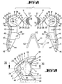
- Fig. 1
- das Schneidwerkzeug in unbetätigter Stellung, in Vorderansicht,
- Fig. 2
- eine Seitenansicht,
- Fig. 3
- die Draufsicht,
- Fig. 4
- das Schneidwerkzeug in Darstellung wie Figur 1, jedoch in betätigter Stellung, also geöffnetem Maul, einen maximalen Rohrquerschnitt aufnehmend,
- Fig. 5
- eine Darstellung wie Fig. 4, jedoch bei gefasstem und bereits stichgeschnittenem Rohr, also in der Schneidbereitschaftsstellung,
- Fig. 6
- eine der Figur 4 entsprechende Darstellung des Schneidwerkzeuges bei weniger weit geöffnetem Maul, ein Rohr kleineren Durchmessers aufnehmend,
- Fig. 7
- eine der Figur 5 entsprechende Darstellung also die Schneidbereitschaftsstellung verkörpernd,
- Fig. 8
- eine Explosionsdarstellung, zeigend die beiden U-profilierten Werkzeughälften im Längsschnitt, die Messerhalterungen in zuordnungsgerechter Ausrichtung, die Schneidmesser in korrekter Einsteckrichtung platziert sowie eine als Rückholfeder fungierende Druckfeder sowohl in Einzeldarstellung als auch in positionierter Stellung, hier jedoch in strichpunktierter Linienart wiedergegeben,
- Fig. 9
- einen Maulabschnitt, nun fertig schneidmesserbestückt und gegenüber Figur 8 vergrößert,
- Fig. 10
- ebenfalls in vergrößerter Wiedergabe eine isoliert dargestellte Messerhalterung in Seitenansicht, vergrößert,
- Fig. 11
- den Schnitt gemäß Linie XI-XI in Figur 9 mit in strichpunktierter Linienart angedeuteter Aufhebung der Klipshalterung (die Messerhalterung selbst ist nicht mitgeschnitten),
- Fig. 12
- die Messerhalterung in Vorderansicht,
- Fig. 13
- dieselbe in vertikal geschnittener Seitenansicht,
- Fig. 14
- die Messerhalterung in Rückansicht,
- Fig. 15
- die Messerhalterung in perspektivischer Darstellung, und zwar gegen die Rückseite gesehen, zusammen mit zuordnungsgerecht ausgerichtetem Schneidmesser.
Claims (9)
- Zangenartiges Schneidwerkzeug zum Abschneiden von Rohren (1), insbesondere Mantelschutzrohren, mit einer kreuzübertrittsfreien Gelenkverbindung (3), bestehend aus zwei jeweils einen Griffabschnitt (4) und einen Maulabschnitt (5) ausbildenden Werkzeughälften (2), wobei die Maulabschnitte (5) jeweils Führungsabschnitte (9) aufweisen, mit einander zugewandten, konkaven Führungsflächen (10), und wobei in einem Führungsabschnitt (9) ein eine Messerspitze (11) aufweisendes Schneidmesser (12) angeordnet ist, dessen Messerspitze (11) auf den gegenüberliegenden Führungsabschnitt (9) gerichtet ist, dadurch gekennzeichnet, dass das Schneidmesser (12) in einer in dem Führungsabschnitt (9) klipsgehalterten Messerhalterung (H) aufgenommen ist.
- Zangenartiges Schneidwerkzeug, nach Anspruch 1, dadurch gekennzeichnet, dass die Messerhaltung (H) einen Teil der Führungsfläche (10) ausformt.
- Zangenartiges Schneidwerkzeug nach Anspruch 1 oder 2, dadurch gekennzeichnet, dass zwei gegenüberliegend jeweils in einer klipsgehalterten Messerhalterung (H) aufgenommene Schneidmesser (12) so zugeordnet ist, dass ihre Messerspitzen (11) auf derselben Radiuslinie (R) bezüglich der Gelenkverbindung (3) liegen und somit auf derselben Bogenbahn (13).
- Zangenartiges Schneidwerkzeug nach einem der vorhergehenden Ansprüche, dadurch gekennzeichnet, dass das Schneidmesser (12) formschlüssig einerseits durch Anlage an einer Überdeckung (16) der Messerhalterung (H) und andererseits durch Anlage an einer Innenfläche (19) des Führungsabschnittes (9) gehaltert ist.
- Zangenartiges Schneidwerkzeug nach einem der vorhergehenden Ansprüche, dadurch gekennzeichnet, dass das Schneidmesser (12) spatenförmig mit einer mittigen Messerspitze (11) ausgebildet ist.
- Zangenartiges Schneidwerkzeug nach einem Ansprüchen der vorhergehenden Ansprüche, dadurch gekennzeichnet, dass die Messerhalterung (H), ausgehend von einer Führungsfläche (23) und gerichtet nach außen zwei gegenüberliegende, federnd gegeneinander bewegbare Halterungsbügel (22) aufweist.
- Zangenartiges Schneidwerkzeug nach einem der vorhergehenden Ansprüche, dadurch gekennzeichnet, dass an einem Halterungsbügel (22) ein nach außen gerichteter Rastzapfen (30) geformt ist, zugeordnet einem freien Halterungsbereich des Halterungsbügels (22).
- Zangenartiges Schneidwerkzeug nach einem der vorhergehenden Ansprüche, dadurch gekennzeichnet, dass zwischen den Halterungsbügeln (22) eine an das Breitenmaß des Schneidmessers (12) angepasste Aufnahmetasche (15) ausgeformt ist.
- Zangenartiges Schneidwerkzeug nach einem der vorhergehenden Ansprüchen, dadurch gekennzeichnet, dass die der Gelenkverbindung (3) abgewandten Enden (9') der Führungsabschnitte (9) in unbetätigter Stellung nicht weiter voneinander beabstandet sind als das Freistandsmaß eines Schneidmessers (12) beträgt.
Applications Claiming Priority (2)
| Application Number | Priority Date | Filing Date | Title |
|---|---|---|---|
| DE19822421 | 1998-05-19 | ||
| DE19822421A DE19822421A1 (de) | 1998-05-19 | 1998-05-19 | Zangenartiges Schneidwerkzeug zum Abschneiden von Rohren |
Publications (3)
| Publication Number | Publication Date |
|---|---|
| EP0958899A2 EP0958899A2 (de) | 1999-11-24 |
| EP0958899A3 EP0958899A3 (de) | 2002-04-10 |
| EP0958899B1 true EP0958899B1 (de) | 2005-02-16 |
Family
ID=7868276
Family Applications (1)
| Application Number | Title | Priority Date | Filing Date |
|---|---|---|---|
| EP99109813A Expired - Lifetime EP0958899B1 (de) | 1998-05-19 | 1999-05-19 | Zangenartiges Schneidwerkzeug zum Abschneiden von Rohren |
Country Status (2)
| Country | Link |
|---|---|
| EP (1) | EP0958899B1 (de) |
| DE (2) | DE19822421A1 (de) |
Families Citing this family (4)
| Publication number | Priority date | Publication date | Assignee | Title |
|---|---|---|---|---|
| DE10233856B4 (de) * | 2001-09-19 | 2006-08-24 | Geberit Mapress Gmbh | Vorrichtung zum Trennen eines Rohres |
| DE102005030735B3 (de) * | 2005-07-01 | 2006-11-16 | Daimlerchrysler Ag | Vorrichtung zum Abschneiden eines Rohrs, insbesondere eines flexiblen Rohrs mit einer Drahtummantelung |
| JP6020936B2 (ja) * | 2014-09-30 | 2016-11-02 | 極東工業株式会社 | パイプカッタ |
| CN109454672A (zh) * | 2018-12-17 | 2019-03-12 | 安徽灿邦电气有限公司 | 一种热缩管剪切装置 |
Family Cites Families (4)
| Publication number | Priority date | Publication date | Assignee | Title |
|---|---|---|---|---|
| GB1383295A (en) * | 1971-11-02 | 1974-02-12 | Gault R | Knives and blades therefor |
| DE3715988C1 (en) * | 1987-05-13 | 1988-08-18 | Huedig Und Rocholz Gmbh & Co K | Severing device for web like material |
| DE9318747U1 (de) * | 1993-12-07 | 1994-02-03 | Taiwan Shin-Lin Company, Ltd., Shen Kang Hsiang, Taichung | Vorrichtung zum Durchschneiden eines Schlauches |
| DE29711774U1 (de) * | 1997-07-04 | 1997-09-18 | Josef Schlemmer GmbH, 85586 Poing | Handschneidegerät zum Abschneiden von Wellrohren |
-
1998
- 1998-05-19 DE DE19822421A patent/DE19822421A1/de not_active Withdrawn
-
1999
- 1999-05-19 DE DE59911629T patent/DE59911629D1/de not_active Expired - Lifetime
- 1999-05-19 EP EP99109813A patent/EP0958899B1/de not_active Expired - Lifetime
Also Published As
| Publication number | Publication date |
|---|---|
| EP0958899A2 (de) | 1999-11-24 |
| EP0958899A3 (de) | 2002-04-10 |
| DE19822421A1 (de) | 1999-11-25 |
| DE59911629D1 (de) | 2005-03-24 |
Similar Documents
| Publication | Publication Date | Title |
|---|---|---|
| US7458160B2 (en) | Ergonomic handle for scissors and other tools | |
| DE69902314T2 (de) | Zange mit ergonomischen Griffen | |
| US5826338A (en) | Wire cutter structure for multipurpose tool | |
| US5937523A (en) | Cigar cutter | |
| EP1354672B1 (de) | Mehrzweckwerkzeug | |
| EP2056415B1 (de) | Abisolierzange | |
| US4442559A (en) | Utility knife | |
| DE60000093T2 (de) | Klappbares Mehrzweckwerkzeug mit Korkenzieher | |
| EP0338243B1 (de) | Schere, insbesondere Friseurschere | |
| DE602004009738T2 (de) | Rasierer | |
| US5491856A (en) | Foldable multiple function tool | |
| DE3245460A1 (de) | Werkzeug, das in der hand zu halten sowie durch einen oeffnungs- und schliessvorgang betaetigbar ist | |
| DE19503840A1 (de) | Messergriff | |
| DE29908436U1 (de) | Eßbesteck | |
| DE60013393T2 (de) | Werkzeug für die Hygiene und zum Schneiden von Häutchen,Finger- und Fussnägeln | |
| EP1031399A1 (de) | Vorrichtung zum Zerteilen von Werkstücken | |
| US6135123A (en) | Hair cutting guide | |
| US4790059A (en) | Carpet laying tool and method of use | |
| CH678906A5 (de) | ||
| EP1469976B1 (de) | Multifunktionswerkzeug | |
| US6550142B1 (en) | Hand tool with retractable implement | |
| EP0958899A2 (de) | Zangenartiges Schneidwerkzeug zum Abschneiden von Rohren | |
| EP3771534A1 (de) | Rollschneider mit auswechselbarer klinge | |
| DE3444871C2 (de) | Chirurgisches Messer mit einer Messerklinge | |
| DE4301764A1 (de) | Mehrzweckwerkzeug |
Legal Events
| Date | Code | Title | Description |
|---|---|---|---|
| PUAI | Public reference made under article 153(3) epc to a published international application that has entered the european phase |
Free format text: ORIGINAL CODE: 0009012 |
|
| AK | Designated contracting states |
Kind code of ref document: A2 Designated state(s): AT BE CH CY DE DK ES FI FR GB GR IE IT LI LU MC NL PT SE Kind code of ref document: A2 Designated state(s): DE ES FR GB IT |
|
| AX | Request for extension of the european patent |
Free format text: AL;LT;LV;MK;RO;SI |
|
| PUAL | Search report despatched |
Free format text: ORIGINAL CODE: 0009013 |
|
| AK | Designated contracting states |
Kind code of ref document: A3 Designated state(s): AT BE CH CY DE DK ES FI FR GB GR IE IT LI LU MC NL PT SE |
|
| AX | Request for extension of the european patent |
Free format text: AL;LT;LV;MK;RO;SI |
|
| 17P | Request for examination filed |
Effective date: 20021004 |
|
| AKX | Designation fees paid |
Free format text: DE ES FR GB IT |
|
| RAP1 | Party data changed (applicant data changed or rights of an application transferred) |
Owner name: EDUARD WILLE GMBH & CO KG |
|
| 17Q | First examination report despatched |
Effective date: 20030507 |
|
| GRAP | Despatch of communication of intention to grant a patent |
Free format text: ORIGINAL CODE: EPIDOSNIGR1 |
|
| GRAS | Grant fee paid |
Free format text: ORIGINAL CODE: EPIDOSNIGR3 |
|
| GRAA | (expected) grant |
Free format text: ORIGINAL CODE: 0009210 |
|
| AK | Designated contracting states |
Kind code of ref document: B1 Designated state(s): DE ES FR GB IT |
|
| PG25 | Lapsed in a contracting state [announced via postgrant information from national office to epo] |
Ref country code: IT Free format text: LAPSE BECAUSE OF FAILURE TO SUBMIT A TRANSLATION OF THE DESCRIPTION OR TO PAY THE FEE WITHIN THE PRESCRIBED TIME-LIMIT;WARNING: LAPSES OF ITALIAN PATENTS WITH EFFECTIVE DATE BEFORE 2007 MAY HAVE OCCURRED AT ANY TIME BEFORE 2007. THE CORRECT EFFECTIVE DATE MAY BE DIFFERENT FROM THE ONE RECORDED. Effective date: 20050216 |
|
| REG | Reference to a national code |
Ref country code: GB Ref legal event code: FG4D Free format text: NOT ENGLISH |
|
| RIN1 | Information on inventor provided before grant (corrected) |
Inventor name: VENNE, WINFRIED Inventor name: WEGERHOFF, DIRK |
|
| REG | Reference to a national code |
Ref country code: IE Ref legal event code: FG4D Free format text: GERMAN |
|
| REF | Corresponds to: |
Ref document number: 59911629 Country of ref document: DE Date of ref document: 20050324 Kind code of ref document: P |
|
| GBT | Gb: translation of ep patent filed (gb section 77(6)(a)/1977) |
Effective date: 20050415 |
|
| PG25 | Lapsed in a contracting state [announced via postgrant information from national office to epo] |
Ref country code: ES Free format text: LAPSE BECAUSE OF FAILURE TO SUBMIT A TRANSLATION OF THE DESCRIPTION OR TO PAY THE FEE WITHIN THE PRESCRIBED TIME-LIMIT Effective date: 20050527 |
|
| PLBE | No opposition filed within time limit |
Free format text: ORIGINAL CODE: 0009261 |
|
| STAA | Information on the status of an ep patent application or granted ep patent |
Free format text: STATUS: NO OPPOSITION FILED WITHIN TIME LIMIT |
|
| ET | Fr: translation filed | ||
| 26N | No opposition filed |
Effective date: 20051117 |
|
| PGFP | Annual fee paid to national office [announced via postgrant information from national office to epo] |
Ref country code: GB Payment date: 20120522 Year of fee payment: 14 Ref country code: FR Payment date: 20120608 Year of fee payment: 14 |
|
| REG | Reference to a national code |
Ref country code: DE Ref legal event code: R082 Ref document number: 59911629 Country of ref document: DE Representative=s name: PATENTANWAELTE WEISSE, MOLTMANN & WILLEMS PART, DE Ref country code: DE Ref legal event code: R082 Ref document number: 59911629 Country of ref document: DE Representative=s name: WEISSE, MOLTMANN & WILLEMS PARTNERSCHAFTGESELL, DE |
|
| GBPC | Gb: european patent ceased through non-payment of renewal fee |
Effective date: 20130519 |
|
| REG | Reference to a national code |
Ref country code: FR Ref legal event code: ST Effective date: 20140131 |
|
| PG25 | Lapsed in a contracting state [announced via postgrant information from national office to epo] |
Ref country code: GB Free format text: LAPSE BECAUSE OF NON-PAYMENT OF DUE FEES Effective date: 20130519 |
|
| PG25 | Lapsed in a contracting state [announced via postgrant information from national office to epo] |
Ref country code: FR Free format text: LAPSE BECAUSE OF NON-PAYMENT OF DUE FEES Effective date: 20130531 |
|
| REG | Reference to a national code |
Ref country code: DE Ref legal event code: R082 Ref document number: 59911629 Country of ref document: DE Representative=s name: PATENTANWAELTE WEISSE, MOLTMANN & WILLEMS PART, DE Ref country code: DE Ref legal event code: R081 Ref document number: 59911629 Country of ref document: DE Owner name: STAHLWILLE EDUARD WILLE GMBH & CO. KG, DE Free format text: FORMER OWNER: EDUARD WILLE GMBH & CO. KG, 42349 WUPPERTAL, DE |
|
| PGFP | Annual fee paid to national office [announced via postgrant information from national office to epo] |
Ref country code: DE Payment date: 20160725 Year of fee payment: 18 |
|
| REG | Reference to a national code |
Ref country code: DE Ref legal event code: R119 Ref document number: 59911629 Country of ref document: DE |
|
| PG25 | Lapsed in a contracting state [announced via postgrant information from national office to epo] |
Ref country code: DE Free format text: LAPSE BECAUSE OF NON-PAYMENT OF DUE FEES Effective date: 20171201 |