EP0955160A2 - Procédé pour la fabrication d'un manchon en particulier pour l'industrie de l'imprimerie - Google Patents
Procédé pour la fabrication d'un manchon en particulier pour l'industrie de l'imprimerie Download PDFInfo
- Publication number
- EP0955160A2 EP0955160A2 EP99108139A EP99108139A EP0955160A2 EP 0955160 A2 EP0955160 A2 EP 0955160A2 EP 99108139 A EP99108139 A EP 99108139A EP 99108139 A EP99108139 A EP 99108139A EP 0955160 A2 EP0955160 A2 EP 0955160A2
- Authority
- EP
- European Patent Office
- Prior art keywords
- sleeve
- tube
- roll core
- inner jacket
- production
- Prior art date
- Legal status (The legal status is an assumption and is not a legal conclusion. Google has not performed a legal analysis and makes no representation as to the accuracy of the status listed.)
- Granted
Links
Images
Classifications
-
- B—PERFORMING OPERATIONS; TRANSPORTING
- B41—PRINTING; LINING MACHINES; TYPEWRITERS; STAMPS
- B41N—PRINTING PLATES OR FOILS; MATERIALS FOR SURFACES USED IN PRINTING MACHINES FOR PRINTING, INKING, DAMPING, OR THE LIKE; PREPARING SUCH SURFACES FOR USE AND CONSERVING THEM
- B41N6/00—Mounting boards; Sleeves Make-ready devices, e.g. underlays, overlays; Attaching by chemical means, e.g. vulcanising
-
- B—PERFORMING OPERATIONS; TRANSPORTING
- B41—PRINTING; LINING MACHINES; TYPEWRITERS; STAMPS
- B41C—PROCESSES FOR THE MANUFACTURE OR REPRODUCTION OF PRINTING SURFACES
- B41C1/00—Forme preparation
- B41C1/18—Curved printing formes or printing cylinders
- B41C1/182—Sleeves; Endless belts
Definitions
- the invention relates to a method for producing a sleeve, in particular for the printing industry, with an essentially inelastic outer jacket and an elastic and compressible inner jacket, in which the sleeve is produced on a production roll core.
- metallic cylinders are mainly used, on the surface of which a functional profile is created.
- Steel rollers are usually galvanically coated with a copper layer, into which the functional profile is then introduced.
- nickel sleeves are also known, which are also produced galvanically.
- the sleeves can be used, for example, as gravure, flexographic or embossed sleeves.
- a pneumatic method is preferably used for removing or re-installing sleeves on a roller core.
- an inner jacket or an expansion layer made of an elastic and compressible material is arranged on the inside of the sleeve.
- This inner jacket or the expansion layer between the roller core and the outer jacket of the sleeve is necessary because the sleeve must not be damaged by excessive pressures when being pulled on or pulled off, and the pressure of the pneumatic means, which is generally caused by radial passages in which the roller core is pressed between the outer shell of the roller core and the inner shell of the sleeve must act on the entire surface in order to enable problem-free removal of the sleeve.
- the inner jacket or the expansion layer has the task of compensating for unevenness on the inside of a tubular sleeve.
- connection of the sleeve to the carrier core which can be made of steel or plastic, for example, can be carried out by means of frictional engagement or positive engagement, the sleeve being produced in the frictional connection on a core which has a slightly smaller diameter than the later carrier core.
- a release agent is first applied to the roll core, on which the expansion layer is then built up. After the expansion layer has dried, its surface must be treated and / or ground down before the outer jacket of the sleeve can be applied in a further step.
- Such a method is very complex, in particular because it is necessary to wait for the expansion layer to harden before the further construction of the sleeve can take place.
- the step of processing the expansion layer after it has hardened, e.g. grinding very time consuming.
- the method according to the invention accordingly comprises the steps of coating the roll core with a release agent, pulling an essentially inelastic tube onto the production roll core, the tube having an inside diameter which is larger than the outside diameter of the production roll core, so that an intermediate space is formed between them, centering the Pipe on the production roll core, so that there is a substantially equal distance between the pipe and the production roll core, injection of a mass forming the elastic and compressible inner jacket into the space between the pipe and the production roll core and hardening of the injected mass.
- the expansion layer or the inner jacket of the sleeve is formed and at the same time a connection is made to the outer jacket of the sleeve, an essentially inelastic tube.
- problems with the connection of the inner jacket and the outer jacket are also avoided, since the inner jacket or the expansion layer can be connected directly to the thermoplastic or metallic tube during injection.
- the expansion layer can also harden after completion of all necessary process steps, so that there is no need to wait for sufficient hardening between the individual process steps.
- the manufacturing process is accelerated, in particular the efficiency of the machines used is improved, since in a method according to the invention no special machine park is necessary during the curing.
- venting devices are preferably closable and are closed as soon as the cavity between the tube and the production roll core is completely filled with the mass forming the inner jacket.
- this ensures a controlled and trouble-free ventilation of the intermediate space, and the mass forming the inner jacket is prevented from escaping from the intermediate space and the possibility is created of compressing the mass in the intermediate space as desired.
- the injection of the mass forming the inner jacket takes place on one side of the space between the production roller core and the tube, while the ventilation is carried out on the opposite side, in the direction of the longitudinal axis of the roller core, which enables and prevents particularly controlled ventilation. that unwanted air pockets remain in the expansion layer or in the inner jacket.
- the above-mentioned ventilation devices and / or injection devices are arranged in a centering device, which the tube in one maintains predetermined, uniform distance from the manufacturing roll core.
- the compact structure provided thereby simplifies the method, and errors due to the interaction of several components can be largely avoided.
- the finished sleeve is preferably removed pneumatically by pressing a liquid or gaseous medium into the roll core and exerting pressure on the sleeve through radial bores in the lateral surface of the production roll core.
- the finished sleeve can be pulled off the production roll core without higher pressures or frictional forces occurring which lead to damage to the inner jacket or the expansion layer.
- the inside of the inner jacket is formed with a structure by a structured surface of the production roll core. This ensures a positive connection between the finished sleeve and a carrier core. Such a positive connection can be desirable, in particular when high forces are to be expected, in order to provide an increased holding force compared to the frictional connection.
- the production roller core preferably consists of metallic materials, in particular aluminum or steel. However, depending on the requirements, other materials can also be used for the production roller core, these are selected in particular for their durability or durability, but also for their weight.
- Closed-cell foams into which additional air bubbles and / or expanded polystyrene beads can be introduced, are particularly suitable as an elastic and compressible mass for the inner jacket.
- Such a material shows excellent elasticity and compression values, while at the same time ensuring a secure connection between the inner jacket and the outer jacket of the sleeve.
- the processing of these foams is also very unproblematic.
- particles can be introduced into the mass forming the inner jacket in order to make the inner jacket electrically conductive.
- the inner jacket consists of two or more layers.
- Such a multilayer structure leads to a higher flexibility of adaptation of the sleeve to the desired task, so that the more complex manufacturing process is accepted.
- a functional profile for later use, in particular in rotary printing, is preferably introduced onto the outer jacket, and further coatings can also be applied to the outer jacket.
- These further coatings are particularly preferably made of polyurethane (PU), polytetrate fluoroethylene (PTFE) or copper and allow problem-free incorporation of a functional profile and also fulfill a protective function for the layers of the sleeve underneath.
- Both the materials for the outer jacket, preferably metallic or thermoplastic material, and the materials of any further coatings are selected and in particular with regard to the desired method for applying a functional profile, such as, for example, direct structuring by means of a laser beam or removal from an ionized state customized.
- a functional layer is additionally glued on, as a result of which the usual manufacturing step of attaching a functional profile, for example by means of direct structuring by means of a laser beam or by removal from the ionized state, is significantly simplified.
- the functional layer can also be a wear protection layer, for example.
- Functional profile should also be understood to mean openings, bores and the like through the sleeve. It is also possible to subsequently provide the sleeve with perforations in the manner of a sieve. Such a sleeve can then be used, for example, as a rotary sieve for sieving bulk goods or as a suction cylinder, for example for sucking in foils or for removing water from paper.
- the production roller core has a conical shape, which in particular simplifies the pneumatic mounting or removal of the sleeve from the roller core.
- a conical course can also be desirable for later use depending on the area of application.
- the production roller core is used directly as a carrier core for the use of the manufactured sleeve. This eliminates the step of pulling off the sleeve, which likewise leads to a simplified processing process and to an immediate introduction of the manufactured sleeve into the manufacturing process.
- all known methods can be used for applying a wide variety of surfaces or layers to the sleeve. These include in particular spraying processes, thermal spraying, fluidized bed sintering, vulcanizing rubber, pouring on or applying shrink sleeves etc.
- All known methods can also be used for structuring the sleeve. These include, in particular, the laser direct structuring already mentioned, which can be variable both in terms of area and depth, the abovementioned removal from the ionized state or mechanical engraving, etc.
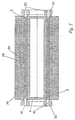
- FIG. 1 shows a cross section through an embodiment of a system which produces a sleeve according to the method according to the invention.
- a roll core 1 which has a compressed air connection 2, through which compressed air is pressed as one of the possible liquid or gaseous media in the roll core, and a radial bore 3 in the outer jacket of the roll core 1, through which the compressed air between the Inner jacket or the expansion layer 60, 65 and the manufacturing roll core 1 is pressed for pneumatic removal or mounting of the sleeve.
- thermoplastic tube 20 is used here as the inelastic tube, which is kept at a uniform distance from the production roll core 1 by means of centering devices 30.
- the methods for applying the surfaces or layers can be selected or used in combination.
- injection nozzles 40 are formed on the one hand, which are directly connected to the space between the thermoplastic tube 20 and the roller core 1, and on the other hand ventilation nozzles 50 on the opposite side of the space, so that a controlled ventilation of the space during the injection of the the inner jacket 60, 65 forming material is guaranteed.
- the inner jacket or the expansion layer 60, 65 has already been injected, the expansion layer being an elastomeric matrix 60 into which expanded polystyrene beads 65 have been introduced.
Applications Claiming Priority (2)
| Application Number | Priority Date | Filing Date | Title |
|---|---|---|---|
| DE19820498 | 1998-05-07 | ||
| DE19820498A DE19820498C2 (de) | 1998-05-07 | 1998-05-07 | Verfahren zum Herstellen einer Hülse, insbesondere für die Druckindustrie |
Publications (3)
| Publication Number | Publication Date |
|---|---|
| EP0955160A2 true EP0955160A2 (fr) | 1999-11-10 |
| EP0955160A3 EP0955160A3 (fr) | 2000-02-23 |
| EP0955160B1 EP0955160B1 (fr) | 2004-01-21 |
Family
ID=7867015
Family Applications (1)
| Application Number | Title | Priority Date | Filing Date |
|---|---|---|---|
| EP99108139A Expired - Lifetime EP0955160B1 (fr) | 1998-05-07 | 1999-04-26 | Procédé pour la fabrication d'un manchon en particulier pour l'industrie de l'imprimerie |
Country Status (3)
| Country | Link |
|---|---|
| EP (1) | EP0955160B1 (fr) |
| AT (1) | ATE258113T1 (fr) |
| DE (2) | DE19820498C2 (fr) |
Cited By (4)
| Publication number | Priority date | Publication date | Assignee | Title |
|---|---|---|---|---|
| WO2001039973A1 (fr) * | 1999-12-03 | 2001-06-07 | Macdermid Graphic Arts S.A. | Un manchon comprenant une couche de solidarisation sur un cylindre support metallique |
| DE10243183C1 (de) * | 2002-03-19 | 2003-08-21 | Polywest Kunststofftechnik | Hülse für den Flexodruck |
| EP1346846A2 (fr) * | 2002-03-19 | 2003-09-24 | POLYWEST KUNSTSTOFFTECHNIK Saueressig & Partner GmbH & Co. KG | Manchon pour l'impression flexographique |
| US6745692B2 (en) | 2002-03-19 | 2004-06-08 | Polywest Kunststofftechnik Saueressig & Partner Gmbh & Co. Kg | Sleeve for flexographic printing |
Families Citing this family (3)
| Publication number | Priority date | Publication date | Assignee | Title |
|---|---|---|---|---|
| DE10127912B4 (de) * | 2001-06-08 | 2011-05-12 | Eastman Kodak Co. | Manschette für einen Zylinder einer Druckmaschine |
| DE10251616B4 (de) * | 2002-11-06 | 2010-03-11 | Eastman Kodak Co. | Verfahren und Einrichtung zum Herstellen einer Beschichtung eines Druckzylinders |
| CN113097943A (zh) * | 2021-03-24 | 2021-07-09 | 来安县友鹏交通设备有限公司 | 一种多层结构的电缆保护管及其生产方法 |
Citations (5)
| Publication number | Priority date | Publication date | Assignee | Title |
|---|---|---|---|---|
| GB2051681A (en) * | 1979-06-25 | 1981-01-21 | Drg Ltd | Printing rolls |
| JPH01163017A (ja) * | 1987-12-03 | 1989-06-27 | Fuji Kako Kk | 硬化性樹脂をライニングしたロールの製造方法 |
| US5089201A (en) * | 1987-12-29 | 1992-02-18 | Canon Kabushiki Kaisha | Method for preparing elastic roller |
| DE19545597A1 (de) * | 1995-12-06 | 1997-06-12 | Polywest Kunststofftechnik | Hülse für Druck- oder Rasterwalzen |
| EP0791477A2 (fr) * | 1996-02-22 | 1997-08-27 | Praxair S.T. Technology, Inc. | Douille pour un rouleau de transfert pour liquide et procédé de fabrication |
-
1998
- 1998-05-07 DE DE19820498A patent/DE19820498C2/de not_active Expired - Fee Related
-
1999
- 1999-04-26 DE DE59908339T patent/DE59908339D1/de not_active Expired - Lifetime
- 1999-04-26 AT AT99108139T patent/ATE258113T1/de not_active IP Right Cessation
- 1999-04-26 EP EP99108139A patent/EP0955160B1/fr not_active Expired - Lifetime
Patent Citations (5)
| Publication number | Priority date | Publication date | Assignee | Title |
|---|---|---|---|---|
| GB2051681A (en) * | 1979-06-25 | 1981-01-21 | Drg Ltd | Printing rolls |
| JPH01163017A (ja) * | 1987-12-03 | 1989-06-27 | Fuji Kako Kk | 硬化性樹脂をライニングしたロールの製造方法 |
| US5089201A (en) * | 1987-12-29 | 1992-02-18 | Canon Kabushiki Kaisha | Method for preparing elastic roller |
| DE19545597A1 (de) * | 1995-12-06 | 1997-06-12 | Polywest Kunststofftechnik | Hülse für Druck- oder Rasterwalzen |
| EP0791477A2 (fr) * | 1996-02-22 | 1997-08-27 | Praxair S.T. Technology, Inc. | Douille pour un rouleau de transfert pour liquide et procédé de fabrication |
Non-Patent Citations (1)
| Title |
|---|
| PATENT ABSTRACTS OF JAPAN vol. 013, no. 425 (M-873), 21. September 1989 (1989-09-21) & JP 01 163017 A (FUJI KAKO KK), 27. Juni 1989 (1989-06-27) * |
Cited By (7)
| Publication number | Priority date | Publication date | Assignee | Title |
|---|---|---|---|---|
| WO2001039973A1 (fr) * | 1999-12-03 | 2001-06-07 | Macdermid Graphic Arts S.A. | Un manchon comprenant une couche de solidarisation sur un cylindre support metallique |
| FR2801833A1 (fr) * | 1999-12-03 | 2001-06-08 | Rollin Sa | Un manchon comprenant une couche de solidarisation sur un cylindre support metallique |
| JP2003515704A (ja) * | 1999-12-03 | 2003-05-07 | マクデルミ・グラフィック・アール・エス・アー | 金属支持シリンダ上の組込みカバーリングを含むスリーブ |
| DE10243183C1 (de) * | 2002-03-19 | 2003-08-21 | Polywest Kunststofftechnik | Hülse für den Flexodruck |
| EP1346846A2 (fr) * | 2002-03-19 | 2003-09-24 | POLYWEST KUNSTSTOFFTECHNIK Saueressig & Partner GmbH & Co. KG | Manchon pour l'impression flexographique |
| US6745692B2 (en) | 2002-03-19 | 2004-06-08 | Polywest Kunststofftechnik Saueressig & Partner Gmbh & Co. Kg | Sleeve for flexographic printing |
| EP1346846A3 (fr) * | 2002-03-19 | 2004-09-08 | POLYWEST KUNSTSTOFFTECHNIK Saueressig & Partner GmbH & Co. KG | Manchon pour l'impression flexographique |
Also Published As
| Publication number | Publication date |
|---|---|
| DE59908339D1 (de) | 2004-02-26 |
| ATE258113T1 (de) | 2004-02-15 |
| EP0955160A3 (fr) | 2000-02-23 |
| DE19820498C2 (de) | 2000-07-06 |
| DE19820498A1 (de) | 1999-11-11 |
| EP0955160B1 (fr) | 2004-01-21 |
Similar Documents
| Publication | Publication Date | Title |
|---|---|---|
| DE102006031336B4 (de) | Verfahren zur Herstellung eines Faserverbundbauteils in der Luft- und Raumfahrt | |
| EP0715966A1 (fr) | Blanchet d'impression tubulaire sans fente | |
| EP0878248A2 (fr) | Manchon pour presses à imprimer rotatives | |
| EP0819550A2 (fr) | Manchon à base de caoutchouc pour machines rotatives offset | |
| EP0955160B1 (fr) | Procédé pour la fabrication d'un manchon en particulier pour l'industrie de l'imprimerie | |
| EP1110748B1 (fr) | Blanchet d'impression comprenant une couche de renforcement isotropique | |
| EP1275520B1 (fr) | Procédé de fabrication d'un blanchet d'impression tubulaire flexible en caoutchouc | |
| DE2817522C3 (de) | Drucktuch | |
| DE102005023331A1 (de) | Druckzylinder und Verfahren zur Herstellung eines Druckzylinders, insbesondere für den Flexodruck | |
| EP1702745B1 (fr) | Procédé de fabrication d'une forme d'impression sans ligne de soudure et cylindre d'impression avec couche superficielle flexible | |
| DE19906855A1 (de) | Verfahren zur Herstellung eines Schwingungsabsorbers | |
| DE60021758T2 (de) | Anordnung mit einer hülse die auf einem metallischen zylinder installiert ist | |
| EP1177100B1 (fr) | Couche extensible constituee d'un materiau compressible | |
| DE2804476A1 (de) | Verfahren und vorrichtung zur laufflaechenbehandlung von reifen | |
| EP1967360B1 (fr) | Manchon et outil de serrage destinés à l'utilisation dans un système constitué d'un outil de serrage et d'au moins un manchon | |
| WO2000032409A1 (fr) | Manchon en materiau thermoformable et procede permettant de le produire | |
| DE2820090C2 (fr) | ||
| DE102007047172A1 (de) | Gummisleeve | |
| EP2274156B1 (fr) | Procédé de fabrication d'un rouleau pour l'usinage d'un matériau en forme de bande et rouleau fabriqué conformément à ce procédé | |
| DE10046559A1 (de) | Druckklischee-Montagesystem | |
| DE4435856C1 (de) | Verfahren zum Herstellen von Faserverbundrohren mit äußerer, metallischer Oberfläche und Vorrichtung zum Durchführen des Verfahrens | |
| WO2003054957A2 (fr) | Composant electronique et son procede de production | |
| DE60006285T2 (de) | Druckhülse mit befestigungsmitteln für druckplatten und verfahren zu ihrer herstellung | |
| DE3246821A1 (de) | Abstandshalter fuer metallische vulkanisierungsformen fuer gummischlaeuche | |
| DE3730791C2 (fr) |
Legal Events
| Date | Code | Title | Description |
|---|---|---|---|
| PUAI | Public reference made under article 153(3) epc to a published international application that has entered the european phase |
Free format text: ORIGINAL CODE: 0009012 |
|
| AK | Designated contracting states |
Kind code of ref document: A2 Designated state(s): AT BE CH DE ES FR GB LI NL |
|
| AX | Request for extension of the european patent |
Free format text: AL;LT;LV;MK;RO;SI |
|
| PUAL | Search report despatched |
Free format text: ORIGINAL CODE: 0009013 |
|
| AK | Designated contracting states |
Kind code of ref document: A3 Designated state(s): AT BE CH CY DE DK ES FI FR GB GR IE IT LI LU MC NL PT SE |
|
| AX | Request for extension of the european patent |
Free format text: AL;LT;LV;MK;RO;SI |
|
| RIC1 | Information provided on ipc code assigned before grant |
Free format text: 7B 41C 1/18 A, 7B 29C 45/14 B, 7B 41N 1/20 B, 7B 41N 1/22 B |
|
| AKX | Designation fees paid | ||
| 17P | Request for examination filed |
Effective date: 20001102 |
|
| RBV | Designated contracting states (corrected) |
Designated state(s): AT BE CH CY DE DK ES FI LI |
|
| RBV | Designated contracting states (corrected) |
Designated state(s): AT BE CH DE ES FR GB LI NL |
|
| 17Q | First examination report despatched |
Effective date: 20030210 |
|
| GRAP | Despatch of communication of intention to grant a patent |
Free format text: ORIGINAL CODE: EPIDOSNIGR1 |
|
| GRAS | Grant fee paid |
Free format text: ORIGINAL CODE: EPIDOSNIGR3 |
|
| GRAA | (expected) grant |
Free format text: ORIGINAL CODE: 0009210 |
|
| AK | Designated contracting states |
Kind code of ref document: B1 Designated state(s): AT BE CH DE ES FR GB LI NL |
|
| PG25 | Lapsed in a contracting state [announced via postgrant information from national office to epo] |
Ref country code: NL Free format text: LAPSE BECAUSE OF FAILURE TO SUBMIT A TRANSLATION OF THE DESCRIPTION OR TO PAY THE FEE WITHIN THE PRESCRIBED TIME-LIMIT Effective date: 20040121 |
|
| REG | Reference to a national code |
Ref country code: GB Ref legal event code: FG4D Free format text: NOT ENGLISH |
|
| REG | Reference to a national code |
Ref country code: CH Ref legal event code: EP |
|
| REF | Corresponds to: |
Ref document number: 59908339 Country of ref document: DE Date of ref document: 20040226 Kind code of ref document: P |
|
| PG25 | Lapsed in a contracting state [announced via postgrant information from national office to epo] |
Ref country code: AT Free format text: LAPSE BECAUSE OF NON-PAYMENT OF DUE FEES Effective date: 20040426 |
|
| PG25 | Lapsed in a contracting state [announced via postgrant information from national office to epo] |
Ref country code: LI Free format text: LAPSE BECAUSE OF NON-PAYMENT OF DUE FEES Effective date: 20040430 Ref country code: CH Free format text: LAPSE BECAUSE OF NON-PAYMENT OF DUE FEES Effective date: 20040430 Ref country code: BE Free format text: LAPSE BECAUSE OF NON-PAYMENT OF DUE FEES Effective date: 20040430 |
|
| PG25 | Lapsed in a contracting state [announced via postgrant information from national office to epo] |
Ref country code: ES Free format text: LAPSE BECAUSE OF FAILURE TO SUBMIT A TRANSLATION OF THE DESCRIPTION OR TO PAY THE FEE WITHIN THE PRESCRIBED TIME-LIMIT Effective date: 20040502 |
|
| GBT | Gb: translation of ep patent filed (gb section 77(6)(a)/1977) |
Effective date: 20040507 |
|
| NLV1 | Nl: lapsed or annulled due to failure to fulfill the requirements of art. 29p and 29m of the patents act | ||
| BERE | Be: lapsed |
Owner name: SAUERESSIG G.M.B.H. & CO. Effective date: 20040430 |
|
| ET | Fr: translation filed | ||
| PLBE | No opposition filed within time limit |
Free format text: ORIGINAL CODE: 0009261 |
|
| STAA | Information on the status of an ep patent application or granted ep patent |
Free format text: STATUS: NO OPPOSITION FILED WITHIN TIME LIMIT |
|
| REG | Reference to a national code |
Ref country code: CH Ref legal event code: PL |
|
| 26N | No opposition filed |
Effective date: 20041022 |
|
| REG | Reference to a national code |
Ref country code: FR Ref legal event code: PLFP Year of fee payment: 18 |
|
| PGFP | Annual fee paid to national office [announced via postgrant information from national office to epo] |
Ref country code: FR Payment date: 20160309 Year of fee payment: 18 |
|
| PGFP | Annual fee paid to national office [announced via postgrant information from national office to epo] |
Ref country code: DE Payment date: 20160429 Year of fee payment: 18 Ref country code: GB Payment date: 20160420 Year of fee payment: 18 |
|
| REG | Reference to a national code |
Ref country code: DE Ref legal event code: R119 Ref document number: 59908339 Country of ref document: DE |
|
| GBPC | Gb: european patent ceased through non-payment of renewal fee |
Effective date: 20170426 |
|
| REG | Reference to a national code |
Ref country code: FR Ref legal event code: ST Effective date: 20171229 |
|
| PG25 | Lapsed in a contracting state [announced via postgrant information from national office to epo] |
Ref country code: FR Free format text: LAPSE BECAUSE OF NON-PAYMENT OF DUE FEES Effective date: 20170502 Ref country code: DE Free format text: LAPSE BECAUSE OF NON-PAYMENT OF DUE FEES Effective date: 20171103 |
|
| PG25 | Lapsed in a contracting state [announced via postgrant information from national office to epo] |
Ref country code: GB Free format text: LAPSE BECAUSE OF NON-PAYMENT OF DUE FEES Effective date: 20170426 |