EP0955160A2 - Process for the fabrication of a sleeve , especially for the printing industrie - Google Patents
Process for the fabrication of a sleeve , especially for the printing industrie Download PDFInfo
- Publication number
- EP0955160A2 EP0955160A2 EP99108139A EP99108139A EP0955160A2 EP 0955160 A2 EP0955160 A2 EP 0955160A2 EP 99108139 A EP99108139 A EP 99108139A EP 99108139 A EP99108139 A EP 99108139A EP 0955160 A2 EP0955160 A2 EP 0955160A2
- Authority
- EP
- European Patent Office
- Prior art keywords
- sleeve
- tube
- roll core
- inner jacket
- production
- Prior art date
- Legal status (The legal status is an assumption and is not a legal conclusion. Google has not performed a legal analysis and makes no representation as to the accuracy of the status listed.)
- Granted
Links
Images
Classifications
-
- B—PERFORMING OPERATIONS; TRANSPORTING
- B41—PRINTING; LINING MACHINES; TYPEWRITERS; STAMPS
- B41N—PRINTING PLATES OR FOILS; MATERIALS FOR SURFACES USED IN PRINTING MACHINES FOR PRINTING, INKING, DAMPING, OR THE LIKE; PREPARING SUCH SURFACES FOR USE AND CONSERVING THEM
- B41N6/00—Mounting boards; Sleeves Make-ready devices, e.g. underlays, overlays; Attaching by chemical means, e.g. vulcanising
-
- B—PERFORMING OPERATIONS; TRANSPORTING
- B41—PRINTING; LINING MACHINES; TYPEWRITERS; STAMPS
- B41C—PROCESSES FOR THE MANUFACTURE OR REPRODUCTION OF PRINTING SURFACES
- B41C1/00—Forme preparation
- B41C1/18—Curved printing formes or printing cylinders
- B41C1/182—Sleeves; Endless belts
Definitions
- the invention relates to a method for producing a sleeve, in particular for the printing industry, with an essentially inelastic outer jacket and an elastic and compressible inner jacket, in which the sleeve is produced on a production roll core.
- metallic cylinders are mainly used, on the surface of which a functional profile is created.
- Steel rollers are usually galvanically coated with a copper layer, into which the functional profile is then introduced.
- nickel sleeves are also known, which are also produced galvanically.
- the sleeves can be used, for example, as gravure, flexographic or embossed sleeves.
- a pneumatic method is preferably used for removing or re-installing sleeves on a roller core.
- an inner jacket or an expansion layer made of an elastic and compressible material is arranged on the inside of the sleeve.
- This inner jacket or the expansion layer between the roller core and the outer jacket of the sleeve is necessary because the sleeve must not be damaged by excessive pressures when being pulled on or pulled off, and the pressure of the pneumatic means, which is generally caused by radial passages in which the roller core is pressed between the outer shell of the roller core and the inner shell of the sleeve must act on the entire surface in order to enable problem-free removal of the sleeve.
- the inner jacket or the expansion layer has the task of compensating for unevenness on the inside of a tubular sleeve.
- connection of the sleeve to the carrier core which can be made of steel or plastic, for example, can be carried out by means of frictional engagement or positive engagement, the sleeve being produced in the frictional connection on a core which has a slightly smaller diameter than the later carrier core.
- a release agent is first applied to the roll core, on which the expansion layer is then built up. After the expansion layer has dried, its surface must be treated and / or ground down before the outer jacket of the sleeve can be applied in a further step.
- Such a method is very complex, in particular because it is necessary to wait for the expansion layer to harden before the further construction of the sleeve can take place.
- the step of processing the expansion layer after it has hardened, e.g. grinding very time consuming.
- the method according to the invention accordingly comprises the steps of coating the roll core with a release agent, pulling an essentially inelastic tube onto the production roll core, the tube having an inside diameter which is larger than the outside diameter of the production roll core, so that an intermediate space is formed between them, centering the Pipe on the production roll core, so that there is a substantially equal distance between the pipe and the production roll core, injection of a mass forming the elastic and compressible inner jacket into the space between the pipe and the production roll core and hardening of the injected mass.
- the expansion layer or the inner jacket of the sleeve is formed and at the same time a connection is made to the outer jacket of the sleeve, an essentially inelastic tube.
- problems with the connection of the inner jacket and the outer jacket are also avoided, since the inner jacket or the expansion layer can be connected directly to the thermoplastic or metallic tube during injection.
- the expansion layer can also harden after completion of all necessary process steps, so that there is no need to wait for sufficient hardening between the individual process steps.
- the manufacturing process is accelerated, in particular the efficiency of the machines used is improved, since in a method according to the invention no special machine park is necessary during the curing.
- venting devices are preferably closable and are closed as soon as the cavity between the tube and the production roll core is completely filled with the mass forming the inner jacket.
- this ensures a controlled and trouble-free ventilation of the intermediate space, and the mass forming the inner jacket is prevented from escaping from the intermediate space and the possibility is created of compressing the mass in the intermediate space as desired.
- the injection of the mass forming the inner jacket takes place on one side of the space between the production roller core and the tube, while the ventilation is carried out on the opposite side, in the direction of the longitudinal axis of the roller core, which enables and prevents particularly controlled ventilation. that unwanted air pockets remain in the expansion layer or in the inner jacket.
- the above-mentioned ventilation devices and / or injection devices are arranged in a centering device, which the tube in one maintains predetermined, uniform distance from the manufacturing roll core.
- the compact structure provided thereby simplifies the method, and errors due to the interaction of several components can be largely avoided.
- the finished sleeve is preferably removed pneumatically by pressing a liquid or gaseous medium into the roll core and exerting pressure on the sleeve through radial bores in the lateral surface of the production roll core.
- the finished sleeve can be pulled off the production roll core without higher pressures or frictional forces occurring which lead to damage to the inner jacket or the expansion layer.
- the inside of the inner jacket is formed with a structure by a structured surface of the production roll core. This ensures a positive connection between the finished sleeve and a carrier core. Such a positive connection can be desirable, in particular when high forces are to be expected, in order to provide an increased holding force compared to the frictional connection.
- the production roller core preferably consists of metallic materials, in particular aluminum or steel. However, depending on the requirements, other materials can also be used for the production roller core, these are selected in particular for their durability or durability, but also for their weight.
- Closed-cell foams into which additional air bubbles and / or expanded polystyrene beads can be introduced, are particularly suitable as an elastic and compressible mass for the inner jacket.
- Such a material shows excellent elasticity and compression values, while at the same time ensuring a secure connection between the inner jacket and the outer jacket of the sleeve.
- the processing of these foams is also very unproblematic.
- particles can be introduced into the mass forming the inner jacket in order to make the inner jacket electrically conductive.
- the inner jacket consists of two or more layers.
- Such a multilayer structure leads to a higher flexibility of adaptation of the sleeve to the desired task, so that the more complex manufacturing process is accepted.
- a functional profile for later use, in particular in rotary printing, is preferably introduced onto the outer jacket, and further coatings can also be applied to the outer jacket.
- These further coatings are particularly preferably made of polyurethane (PU), polytetrate fluoroethylene (PTFE) or copper and allow problem-free incorporation of a functional profile and also fulfill a protective function for the layers of the sleeve underneath.
- Both the materials for the outer jacket, preferably metallic or thermoplastic material, and the materials of any further coatings are selected and in particular with regard to the desired method for applying a functional profile, such as, for example, direct structuring by means of a laser beam or removal from an ionized state customized.
- a functional layer is additionally glued on, as a result of which the usual manufacturing step of attaching a functional profile, for example by means of direct structuring by means of a laser beam or by removal from the ionized state, is significantly simplified.
- the functional layer can also be a wear protection layer, for example.
- Functional profile should also be understood to mean openings, bores and the like through the sleeve. It is also possible to subsequently provide the sleeve with perforations in the manner of a sieve. Such a sleeve can then be used, for example, as a rotary sieve for sieving bulk goods or as a suction cylinder, for example for sucking in foils or for removing water from paper.
- the production roller core has a conical shape, which in particular simplifies the pneumatic mounting or removal of the sleeve from the roller core.
- a conical course can also be desirable for later use depending on the area of application.
- the production roller core is used directly as a carrier core for the use of the manufactured sleeve. This eliminates the step of pulling off the sleeve, which likewise leads to a simplified processing process and to an immediate introduction of the manufactured sleeve into the manufacturing process.
- all known methods can be used for applying a wide variety of surfaces or layers to the sleeve. These include in particular spraying processes, thermal spraying, fluidized bed sintering, vulcanizing rubber, pouring on or applying shrink sleeves etc.
- All known methods can also be used for structuring the sleeve. These include, in particular, the laser direct structuring already mentioned, which can be variable both in terms of area and depth, the abovementioned removal from the ionized state or mechanical engraving, etc.
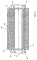
- FIG. 1 shows a cross section through an embodiment of a system which produces a sleeve according to the method according to the invention.
- a roll core 1 which has a compressed air connection 2, through which compressed air is pressed as one of the possible liquid or gaseous media in the roll core, and a radial bore 3 in the outer jacket of the roll core 1, through which the compressed air between the Inner jacket or the expansion layer 60, 65 and the manufacturing roll core 1 is pressed for pneumatic removal or mounting of the sleeve.
- thermoplastic tube 20 is used here as the inelastic tube, which is kept at a uniform distance from the production roll core 1 by means of centering devices 30.
- the methods for applying the surfaces or layers can be selected or used in combination.
- injection nozzles 40 are formed on the one hand, which are directly connected to the space between the thermoplastic tube 20 and the roller core 1, and on the other hand ventilation nozzles 50 on the opposite side of the space, so that a controlled ventilation of the space during the injection of the the inner jacket 60, 65 forming material is guaranteed.
- the inner jacket or the expansion layer 60, 65 has already been injected, the expansion layer being an elastomeric matrix 60 into which expanded polystyrene beads 65 have been introduced.
Abstract
Description
Die Erfindung bezieht sich auf ein Verfahren zum Herstellen einer Hülse, insbesondere für die Druckindustrie, mit einem im wesentlichen unelastischen Außenmantel und einem elastischen und kompressiblen Innenmantel, bei dem die Hülse auf einem Fertigungswalzenkern hergestellt wird.The invention relates to a method for producing a sleeve, in particular for the printing industry, with an essentially inelastic outer jacket and an elastic and compressible inner jacket, in which the sleeve is produced on a production roll core.
Für Hülsen, insbesondere im Bereich der Rotationsdruckformen in der Druckindustrie, kommen vorwiegend metallische Zylinder zum Einsatz, auf deren Oberfläche ein Funktionsprofil erzeugt wird. Üblicherweise werden Stahlwalzen galvanisch mit einer Kupferschicht überzogen, in die dann das Funktionsprofil eingebracht wird. Ferner sind auch Nickel-Hülsen bekannt, die ebenfalls galvanisch hergestellt werden.For sleeves, especially in the field of rotary printing forms in the printing industry, metallic cylinders are mainly used, on the surface of which a functional profile is created. Steel rollers are usually galvanically coated with a copper layer, into which the functional profile is then introduced. Furthermore, nickel sleeves are also known, which are also produced galvanically.
Die Hülsen können beispielsweise als Tief-, Flexodruck oder Prägehülse eingesetzt werden.The sleeves can be used, for example, as gravure, flexographic or embossed sleeves.
Für das Entfernen bzw. das Wiederaufziehen von Hülsen auf einem Walzenkern wird bevorzugt ein pneumatisches Verfahren angewendet. Zu diesem Zweck ist auf der Innenseite der Hülse ein Innenmantel bzw. eine Dehnschicht aus einem elastischen und kompressiblen Material angeordnet. Dieser Innenmantel bzw. die Dehnschicht zwischen dem Walzenkern und dem Außenmantel der Hülse ist notwendig, da die Hülse zum einen beim Aufziehen bzw. Abziehen nicht durch zu hohe Drücke beschädigt werden darf und zum anderen der Druck des pneumatischen Mittels, der im allgemeinen durch radiale Durchlässe in dem Walzenkern zwischen Außenmantel des Walzenkerns und Innenmantel der Hülse gedrückt wird, auf der gesamten Fläche wirksam werden muß, um ein problemloses Entfernen der Hülse zu ermöglichen. Ferner haben der Innenmantel bzw. die Dehnschicht die Aufgabe, auf der Innenseite einer rohrförmigen Hülse Unebenheiten auszugleichen.A pneumatic method is preferably used for removing or re-installing sleeves on a roller core. For this purpose, an inner jacket or an expansion layer made of an elastic and compressible material is arranged on the inside of the sleeve. This inner jacket or the expansion layer between the roller core and the outer jacket of the sleeve is necessary because the sleeve must not be damaged by excessive pressures when being pulled on or pulled off, and the pressure of the pneumatic means, which is generally caused by radial passages in which the roller core is pressed between the outer shell of the roller core and the inner shell of the sleeve must act on the entire surface in order to enable problem-free removal of the sleeve. Furthermore, the inner jacket or the expansion layer has the task of compensating for unevenness on the inside of a tubular sleeve.
Die Verbindung der Hülse zum Trägerkern, der zum Beispiel aus Stahl oder Kunststoff hergestellt sein kann, kann mittels Reibschluß oder Formschluß erfolgen, wobei bei der reibschlüssigen Verbindung die Hülse auf einem Kern hergestellt wird, der einen geringfügig kleineren Durchmesser als der spätere Trägerkern aufweist.The connection of the sleeve to the carrier core, which can be made of steel or plastic, for example, can be carried out by means of frictional engagement or positive engagement, the sleeve being produced in the frictional connection on a core which has a slightly smaller diameter than the later carrier core.
Es sind Verfahren bekannt, bei denen auf den Walzenkern zuerst ein Trennmittel aufgebracht wird, auf dem dann die Dehnschicht aufgebaut wird. Nach einem Trocknen der Dehnschicht muß deren Oberfläche behandelt und/oder abgeschliffen werden, bevor in einem weiteren Schritt der Außenmantel der Hülse aufgebracht werden kann. Ein solches Verfahren ist sehr aufwendig, insbesondere deshalb, weil auf das Aushärten der Dehnschicht gewartet werden muß, bevor der weitere Aufbau der Hülse erfolgen kann. Ferner ist der Schritt der Bearbeitung der Dehnschicht nach deren Aushärtung, z.B. das Schleifen, sehr zeitaufwendig.Methods are known in which a release agent is first applied to the roll core, on which the expansion layer is then built up. After the expansion layer has dried, its surface must be treated and / or ground down before the outer jacket of the sleeve can be applied in a further step. Such a method is very complex, in particular because it is necessary to wait for the expansion layer to harden before the further construction of the sleeve can take place. Furthermore, the step of processing the expansion layer after it has hardened, e.g. grinding, very time consuming.
Es ist demnach die Aufgabe der vorliegenden Erfindung, ein Verfahren zum Herstellen einer Hülse mit einem im wesentlichen unelastischen Außenmantel und einem elastischen und kompressiblen Innenmantel zur Verfügung zu stellen, das die notwendigen Verfahrensschritte minimiert und insbesondere Zeitverzögerungen zwischen den einzelnen Verfahrensschritten, die zum Beispiel auf Aushärtezeiten etc. beruhen, zu vermeiden.It is therefore the object of the present invention to provide a method for producing a sleeve with a substantially inelastic outer jacket and an elastic and compressible inner jacket, which minimizes the necessary process steps and in particular time delays between the individual process steps, for example due to curing times etc. to avoid.
Diese Aufgabe wird durch ein Verfahren gemäß Anspruch 1 gelöst, bevorzugte Ausführungen sind Gegenstand der Unteransprüche.This object is achieved by a method according to claim 1, preferred embodiments are the subject of the dependent claims.
Das erfindungsgemäße Verfahren umfaßt demnach die Schritte Beschichten des Walzenkerns mit einem Trennmittel, Aufziehen eines im wesentlichen unelastischen Rohres auf den Fertigungswalzenkern, wobei das Rohr einen Innendurchmesser aufweist, der größer ist als der Außendurchmesser des Fertigungswalzenkernes, so daß zwischen diesen ein Zwischenraum entsteht, Zentrieren des Rohres auf dem Fertigungswalzenkern, so daß ein im wesentlichen gleicher Abstand zwischen Rohr und Fertigungswalzenkern entsteht, Injektion einer den elastischen und kompressiblen Innenmantel bildenden Masse in den Zwischenraum zwischen Rohr und Fertigungswalzenkern und Aushärten der injizierten Masse.The method according to the invention accordingly comprises the steps of coating the roll core with a release agent, pulling an essentially inelastic tube onto the production roll core, the tube having an inside diameter which is larger than the outside diameter of the production roll core, so that an intermediate space is formed between them, centering the Pipe on the production roll core, so that there is a substantially equal distance between the pipe and the production roll core, injection of a mass forming the elastic and compressible inner jacket into the space between the pipe and the production roll core and hardening of the injected mass.
Dadurch wird in einem einzigen Verfahrensschritt zum einen die Dehnschicht bzw. der Innenmantel der Hülse gebildet und gleichzeitig eine Verbindung mit dem Außenmantel der Hülse, einem im wesentlichen unelastischen Rohr, hergestellt. Neben der deutlichen Vereinfachung des Verfahrensablaufs werden darüber hinaus Problematiken bei der Verbindung des Innenmantels und des Außenmantels vermieden, da sich der Innenmantel bzw. die Dehnschicht bei der Injektion direkt mit dem thermoplastischen oder metallischen Rohr verbinden kann.As a result, in a single process step, the expansion layer or the inner jacket of the sleeve is formed and at the same time a connection is made to the outer jacket of the sleeve, an essentially inelastic tube. In addition to the significant simplification of the process sequence, problems with the connection of the inner jacket and the outer jacket are also avoided, since the inner jacket or the expansion layer can be connected directly to the thermoplastic or metallic tube during injection.
Die Dehnschicht kann darüberhinaus nach Abschluß sämtlicher notwendiger Verfahrensschritte aushärten, so daß nicht zwischen den einzelnen Verfahrensschritten auf eine ausreichende Aushärtung gewartet werden muß. Dadurch wird der Herstellungsprozeß beschleunigt, insbesondere die Effizienz der eingesetzten Maschinen verbessert, da bei einem erfindungsgemäßen Verfahren während der Aushärtung kein spezieller Maschinenpark notwendig ist.The expansion layer can also harden after completion of all necessary process steps, so that there is no need to wait for sufficient hardening between the individual process steps. As a result, the manufacturing process is accelerated, in particular the efficiency of the machines used is improved, since in a method according to the invention no special machine park is necessary during the curing.
Bevorzugt ist vorgesehen, daß der Zwischenraum zwischen Rohr und Fertigungswalzenkern während der Injektion der den Innenmantel bildenden Masse durch Entlüftungsvorrichtungen entlüftet wird. Diese Entlüftungsvorrichtungen sind bevorzugt verschließbar und werden geschlossen, sobald der Hohlraum zwischen Rohr und Fertigungswalzenkern vollständig mit der den Innenmantel bildenden Masse gefüllt ist. Dadurch wird zum einen eine kontrollierte und störungsfreie Entlüftung des Zwischenraumes sichergestellt, ferner wird ein Austreten der den Innenmantel bildenden Masse aus dem Zwischenraum verhindert und die Möglichkeit geschaffen, die Masse in dem Zwischenraum wunschgemäß zu komprimieren.It is preferably provided that the space between the tube and the production roll core is vented by venting devices during the injection of the mass forming the inner jacket. These venting devices are preferably closable and are closed as soon as the cavity between the tube and the production roll core is completely filled with the mass forming the inner jacket. On the one hand, this ensures a controlled and trouble-free ventilation of the intermediate space, and the mass forming the inner jacket is prevented from escaping from the intermediate space and the possibility is created of compressing the mass in the intermediate space as desired.
Bei einer bevorzugten Ausführungsform findet die Injektion der den Innenmantel bildenden Masse an einer Seite des Zwischenraumes zwischen Fertigungswalzenkern und Rohr statt, während die Entlüftung an der gegenüberliegenden Seite, in Richtung der Längsachse des Walzenkerns, durchgeführt wird, was eine besonders kontrollierte Entlüftung ermöglicht und verhindert, daß ungewollte Lufteinschlüsse in der Dehnschicht bzw. in dem Innenmantel verbleiben.In a preferred embodiment, the injection of the mass forming the inner jacket takes place on one side of the space between the production roller core and the tube, while the ventilation is carried out on the opposite side, in the direction of the longitudinal axis of the roller core, which enables and prevents particularly controlled ventilation. that unwanted air pockets remain in the expansion layer or in the inner jacket.
Besonders bevorzugt ist, daß die oben genannten Entlüftungsvorrichtungen und/oder Injektionsvorrichtungen in einer Zentriervorrichtung angeordnet sind, die das Rohr in einem vorbestimmten, gleichmäßigen Abstand von dem Fertigungswalzenkern hält. Durch den dadurch zur Verfügung gestellten kompakten Aufbau wird das Verfahren vereinfacht, ferner können Fehler durch Zusammenwirken mehrerer Komponenten weitgehend vermieden werden.It is particularly preferred that the above-mentioned ventilation devices and / or injection devices are arranged in a centering device, which the tube in one maintains predetermined, uniform distance from the manufacturing roll core. The compact structure provided thereby simplifies the method, and errors due to the interaction of several components can be largely avoided.
Bevorzugt wird die Entnahme der fertiggestellten Hülse pneumatisch durchgeführt, indem ein flüssiges oder gasförmiges Medium in den Walzenkern gedrückt wird und durch radiale Bohrungen in der Mantelfläche des Fertigungswalzenkernes Druck auf die Hülse ausübt. Dadurch läßt sich die fertiggestellte Hülse von dem Fertigungswalzenkern abziehen, ohne daß höhere Drücke bzw. Reibungskräfte auftreten, die zu einer Beschädigung des Innenmantels bzw. der Dehnschicht führen.The finished sleeve is preferably removed pneumatically by pressing a liquid or gaseous medium into the roll core and exerting pressure on the sleeve through radial bores in the lateral surface of the production roll core. As a result, the finished sleeve can be pulled off the production roll core without higher pressures or frictional forces occurring which lead to damage to the inner jacket or the expansion layer.
Bei einer weiteren Ausführungsform wird die Innenseite des Innenmantels durch eine strukturierte Oberfläche des Fertigungswalzenkernes mit einer Struktur ausgebildet. Dadurch wird eine formschlüssige Verbindung zwischen der fertiggestellten Hülse und einem Tägerkern sichergestellt. Eine solche formschlüssige Verbindung kann insbesondere bei hohen zu erwartenden Kräften wünschenswert sein, um eine gegenüber der reibschlüssigen Verbindung erhöhte Haltekraft zur Verfügung zu stellen.In a further embodiment, the inside of the inner jacket is formed with a structure by a structured surface of the production roll core. This ensures a positive connection between the finished sleeve and a carrier core. Such a positive connection can be desirable, in particular when high forces are to be expected, in order to provide an increased holding force compared to the frictional connection.
Der Fertigungswalzenkern besteht bevorzugt aus metallischen Materialien, insbesondere Aluminium oder Stahl. Es können aber je nach Anforderungen auch andere Materialen für den Fertigungswalzenkern verwendet werden, diese werden insbesondere nach ihrer Haltbarkeit bzw. Beständigkeit, aber auch nach ihrem Gewicht, ausgesucht.The production roller core preferably consists of metallic materials, in particular aluminum or steel. However, depending on the requirements, other materials can also be used for the production roller core, these are selected in particular for their durability or durability, but also for their weight.
Als elastische und kompressible Masse für den Innenmantel eignen sich besonders geschlossenzellige Schäume, in die zusätzlich Luftbläschen und/oder expandierte Polystyrolperlen eingebracht werden können. Ein solches Material zeigt hervorragende Elastizitäts- und Kompressionswerte, wobei gleichzeitig eine sichere Verbindung zwischen Innenmantel und Außenmantel der Hülse sichergestellt bleibt. Auch die Verarbeitung dieser Schäume ist sehr unproblematisch.Closed-cell foams, into which additional air bubbles and / or expanded polystyrene beads can be introduced, are particularly suitable as an elastic and compressible mass for the inner jacket. Such a material shows excellent elasticity and compression values, while at the same time ensuring a secure connection between the inner jacket and the outer jacket of the sleeve. The processing of these foams is also very unproblematic.
Ferner können Partikel in die den Innenmantel bildende Masse eingebracht werden, um den Innenmantel elektrisch leitfähig zu machen.Furthermore, particles can be introduced into the mass forming the inner jacket in order to make the inner jacket electrically conductive.
Bei einer weiteren Ausführungsform besteht der Innenmantel aus zwei oder mehr Schichten. Ein solcher mehrschichtiger Aufbau führt zu einer höheren Anpassungsflexibilität der Hülse an die gewünschte Aufgabe, so daß der komplexere Herstellungsablauf in Kauf genommen wird.In a further embodiment, the inner jacket consists of two or more layers. Such a multilayer structure leads to a higher flexibility of adaptation of the sleeve to the desired task, so that the more complex manufacturing process is accepted.
Bevorzugt wird auf den Außenmantel ein Funktionsprofil für den späteren Einsatz, insbesondere beim Rotationsdruck, eingebracht, ferner können auf den Außenmantel zusätzlich weitere Beschichtungen aufgebracht werden. Diese weiteren Beschichtungen bestehen besonders bevorzugt aus Polyurethan (PU), Polytetratfluorethylen (PTFE) oder Kupfer und erlauben eine problemlose Einarbeitung eines Funktionsprofils und erfüllen darüber hinaus eine Schutzfunktion für die darunterliegenden Schichten der Hülse.A functional profile for later use, in particular in rotary printing, is preferably introduced onto the outer jacket, and further coatings can also be applied to the outer jacket. These further coatings are particularly preferably made of polyurethane (PU), polytetrate fluoroethylene (PTFE) or copper and allow problem-free incorporation of a functional profile and also fulfill a protective function for the layers of the sleeve underneath.
Sowohl die Materialien für den Außenmantel, bevorzugt metallisches oder thermoplastisches Material, als auch die Materialien eventuell weiterer Beschichtungen werden insbesondere im Hinblick auf die gewünschte Methode für das Aufbringen eines Funktionsprofils, wie zum Beispiel Direktstrukturierung mittels eines Laserstrahls oder Abtragen aus einem ionisierten Zustand, ausgesucht und angepaßt.Both the materials for the outer jacket, preferably metallic or thermoplastic material, and the materials of any further coatings are selected and in particular with regard to the desired method for applying a functional profile, such as, for example, direct structuring by means of a laser beam or removal from an ionized state customized.
Bei einer weiteren Ausführungsform ist vorgesehen, daß zusätzlich eine Funktionsschicht aufgeklebt wird, wodurch der übliche Fertigungsschritt des Anbringens eines Funktionsprofils, zum Beispiel mittels Direktstrukturierung durch einen Laserstrahl oder durch Abtragen aus dem ionisierten Zustand, deutlich vereinfacht wird.In a further embodiment it is provided that a functional layer is additionally glued on, as a result of which the usual manufacturing step of attaching a functional profile, for example by means of direct structuring by means of a laser beam or by removal from the ionized state, is significantly simplified.
Die Funktionsschicht kann beispielsweise auch eine Verschleißschutzschicht sein.The functional layer can also be a wear protection layer, for example.
Unter Funktionsprofil sollen auch Durchbrüche, Bohrungen und dergleichen durch die Hülse verstanden werden. So ist es auch möglich, die Hülse nachträglich mit Perforationen nach Art eines Siebes zu versehen. Dann kann eine solche Hülse beispielsweise als Rotationssieb zum Sieben von Schüttgütern oder als Saugzylinder, zum Beispiel um Folien anzusaugen oder um Wasser aus Papier abzuziehen, eingesetzt werden.Functional profile should also be understood to mean openings, bores and the like through the sleeve. It is also possible to subsequently provide the sleeve with perforations in the manner of a sieve. Such a sleeve can then be used, for example, as a rotary sieve for sieving bulk goods or as a suction cylinder, for example for sucking in foils or for removing water from paper.
Durch die flexible Gestaltung der Oberfläche wird auch die Verwendung als Textildruckschablone möglich.Thanks to the flexible design of the surface, it can also be used as a textile printing template.
Bei einer weiteren Ausführungsform weist der Fertigungswalzenkern einen konischen Verlauf auf, wodurch insbesondere das pneumatische Aufziehen bzw. Entfernen der Hülse von dem Walzenkern vereinfacht wird. Ein solcher konischer Verlauf kann aber auch je nach Anwendungsgebiet für den späteren Einsatz wünschenswert sein.In a further embodiment, the production roller core has a conical shape, which in particular simplifies the pneumatic mounting or removal of the sleeve from the roller core. Such a conical course can also be desirable for later use depending on the area of application.
In einer weiteren bevorzugten Ausführungsform wird der Fertigungswalzenkern direkt als Trägerkern für den Einsatz der gefertigten Hülse verwendet. Dadurch wird der Schritt des Abziehens der Hülse entbehrlich, was ebenfalls zu einem vereinfachten Verarbeitungsprozeß und zu einem unverzüglichen Einbringen der hergestellten Hülse in den Fertigungsprozeß führt.In a further preferred embodiment, the production roller core is used directly as a carrier core for the use of the manufactured sleeve. This eliminates the step of pulling off the sleeve, which likewise leads to a simplified processing process and to an immediate introduction of the manufactured sleeve into the manufacturing process.
Grundsätzlich können für das Aufbringen unterschiedlichster Oberflächen bzw. Schichten auf die Hülse alle bekannten Verfahren verwendet werden. Dazu zählen insbesondere Spritzverfahren, thermisches Spritzen, Wirbelsintern, Aufvulkanisieren von Gummi, Aufgießen oder das Aufbringen von Schrumpfschläuchen etc.In principle, all known methods can be used for applying a wide variety of surfaces or layers to the sleeve. These include in particular spraying processes, thermal spraying, fluidized bed sintering, vulcanizing rubber, pouring on or applying shrink sleeves etc.
Auch für die Strukturierung der Hülse können alle bekannten Verfahren eingesetzt werden. Dazu zählen insbesondere die bereits erwähnte Laserdirektstrukturierung, wobei diese sowohl flächen- als auch tiefenvariabel sein kann, das ebenfalls bereits erwähnte Abtragen aus dem ionisierten Zustand oder eine mechanische Gravur etc.All known methods can also be used for structuring the sleeve. These include, in particular, the laser direct structuring already mentioned, which can be variable both in terms of area and depth, the abovementioned removal from the ionized state or mechanical engraving, etc.
Das erfindungsgemäße Verfahren wird anhand der beiliegenden Figur 1, die einen Querschnitt durch eine Ausführungsform eines Systems zeigt, das eine Hülse nach dem erfindungsgemäßen Verfahren herstellt, näher erläutert.The method according to the invention is explained in more detail with reference to the attached FIG. 1, which shows a cross section through an embodiment of a system which produces a sleeve according to the method according to the invention.
In Figur 1 ist ein Walzenkern 1 gezeigt, der einen Drückluftanschluß 2, durch den Druckluft als eines der möglichen flüssigen oder gasförmigen Medien in den Walzenkern gedrückt wird, und eine radiale Bohrung 3 in dem Außenmantel des Walzenkernes 1 aufweist, durch den die Druckluft zwischen den Innenmantel bzw. die Dehnschicht 60, 65 und den Fertigungswalzenkern 1 für ein pneumatisches Entfernen bzw. Aufziehen der Hülse gedrückt wird.In Figure 1, a roll core 1 is shown, which has a
Als unelastisches Rohr wird hier ein thermoplastisches Rohr 20 verwendet, das mittels Zentriervorrichtungen 30 in einem gleichmäßigen Abstand von dem Fertigungswalzenkern 1 gehalten wird.A
Die Verfahren zum Aufbringen der Oberflächen bzw. Schichten können je nach Anwendung beliebig ausgewählt oder kombiniert angewendet werden.Depending on the application, the methods for applying the surfaces or layers can be selected or used in combination.
In den Zentriervorrichtungen 30 sind zum einen Injektionsdüsen 40 eingeformt, die direkt in Verbindung mit dem Zwischenraum zwischen dem thermoplastischen Rohr 20 und dem Walzenkern 1 stehen, zum anderen Entlüftungsdüsen 50 auf der gegenüberliegenden Seite des Zwischenraumes, damit eine kontrollierte Entlüftung des Zwischenraumes während der Injektion des den Innenmantel 60, 65 bildenden Materials gewährleistet ist.In the
In der Figur 1 ist der Innenmantel bzw. die Dehnschicht 60, 65 bereits injiziert, wobei die Dehnschicht eine elastomere Matrix 60 ist, in die expandierte Polystyrolperlen 65 eingebracht worden sind.In FIG. 1, the inner jacket or the
Die in der vorstehenden Beschreibung, in der Zeichnung sowie in den Ansprüchen offenbarten Merkmale der Erfindung können sowohl einzeln als auch in beliebiger Kombination für die Verwirklichung der Erfindung wesentlich sein.The features of the invention disclosed in the above description, in the drawing and in the claims can be essential for realizing the invention both individually and in any combination.
Claims (23)
dadurch gekennzeichnet, daß das Verfahren folgende Schritte umfaßt:
characterized in that the method comprises the following steps:
dadurch gekennzeichnet, daß zusätzlich Partikel in die den Innenmantel bildende Masse (60, 65) eingebracht werden, die den Innenmantel leitfähig machen.Method according to one of the preceding claims,
characterized in that particles are additionally introduced into the mass (60, 65) forming the inner jacket, which make the inner jacket conductive.
Applications Claiming Priority (2)
| Application Number | Priority Date | Filing Date | Title |
|---|---|---|---|
| DE19820498A DE19820498C2 (en) | 1998-05-07 | 1998-05-07 | Process for manufacturing a sleeve, in particular for the printing industry |
| DE19820498 | 1998-05-07 |
Publications (3)
| Publication Number | Publication Date |
|---|---|
| EP0955160A2 true EP0955160A2 (en) | 1999-11-10 |
| EP0955160A3 EP0955160A3 (en) | 2000-02-23 |
| EP0955160B1 EP0955160B1 (en) | 2004-01-21 |
Family
ID=7867015
Family Applications (1)
| Application Number | Title | Priority Date | Filing Date |
|---|---|---|---|
| EP99108139A Expired - Lifetime EP0955160B1 (en) | 1998-05-07 | 1999-04-26 | Process for the fabrication of a sleeve , especially for the printing industrie |
Country Status (3)
| Country | Link |
|---|---|
| EP (1) | EP0955160B1 (en) |
| AT (1) | ATE258113T1 (en) |
| DE (2) | DE19820498C2 (en) |
Cited By (4)
| Publication number | Priority date | Publication date | Assignee | Title |
|---|---|---|---|---|
| WO2001039973A1 (en) * | 1999-12-03 | 2001-06-07 | Macdermid Graphic Arts S.A. | Sleeve comprising a layer for being fixed on a metal support roll |
| DE10243183C1 (en) * | 2002-03-19 | 2003-08-21 | Polywest Kunststofftechnik | Sleeve for use on flexoprinting machines comprises an electrically conductive surface which is joined to a contact zone on the sleeve carrier cylinder via an electrically conductive unit accommodated in the sleeve body |
| EP1346846A2 (en) * | 2002-03-19 | 2003-09-24 | POLYWEST KUNSTSTOFFTECHNIK Saueressig & Partner GmbH & Co. KG | Sleeve for flexographic printing |
| US6745692B2 (en) | 2002-03-19 | 2004-06-08 | Polywest Kunststofftechnik Saueressig & Partner Gmbh & Co. Kg | Sleeve for flexographic printing |
Families Citing this family (3)
| Publication number | Priority date | Publication date | Assignee | Title |
|---|---|---|---|---|
| DE10127912B4 (en) * | 2001-06-08 | 2011-05-12 | Eastman Kodak Co. | Cuff for a cylinder of a printing machine |
| DE10251616B4 (en) * | 2002-11-06 | 2010-03-11 | Eastman Kodak Co. | Method and device for producing a coating of a printing cylinder |
| CN113097943A (en) * | 2021-03-24 | 2021-07-09 | 来安县友鹏交通设备有限公司 | Cable protection pipe with multilayer structure and production method thereof |
Citations (5)
| Publication number | Priority date | Publication date | Assignee | Title |
|---|---|---|---|---|
| GB2051681A (en) * | 1979-06-25 | 1981-01-21 | Drg Ltd | Printing rolls |
| JPH01163017A (en) * | 1987-12-03 | 1989-06-27 | Fuji Kako Kk | Manufacture of roll lined with cured resin |
| US5089201A (en) * | 1987-12-29 | 1992-02-18 | Canon Kabushiki Kaisha | Method for preparing elastic roller |
| DE19545597A1 (en) * | 1995-12-06 | 1997-06-12 | Polywest Kunststofftechnik | Shell for printing or screen roll |
| EP0791477A2 (en) * | 1996-02-22 | 1997-08-27 | Praxair S.T. Technology, Inc. | Sleeve for a liquid transfer roll and method for producing it |
-
1998
- 1998-05-07 DE DE19820498A patent/DE19820498C2/en not_active Expired - Fee Related
-
1999
- 1999-04-26 AT AT99108139T patent/ATE258113T1/en not_active IP Right Cessation
- 1999-04-26 DE DE59908339T patent/DE59908339D1/en not_active Expired - Lifetime
- 1999-04-26 EP EP99108139A patent/EP0955160B1/en not_active Expired - Lifetime
Patent Citations (5)
| Publication number | Priority date | Publication date | Assignee | Title |
|---|---|---|---|---|
| GB2051681A (en) * | 1979-06-25 | 1981-01-21 | Drg Ltd | Printing rolls |
| JPH01163017A (en) * | 1987-12-03 | 1989-06-27 | Fuji Kako Kk | Manufacture of roll lined with cured resin |
| US5089201A (en) * | 1987-12-29 | 1992-02-18 | Canon Kabushiki Kaisha | Method for preparing elastic roller |
| DE19545597A1 (en) * | 1995-12-06 | 1997-06-12 | Polywest Kunststofftechnik | Shell for printing or screen roll |
| EP0791477A2 (en) * | 1996-02-22 | 1997-08-27 | Praxair S.T. Technology, Inc. | Sleeve for a liquid transfer roll and method for producing it |
Non-Patent Citations (1)
| Title |
|---|
| PATENT ABSTRACTS OF JAPAN vol. 013, no. 425 (M-873), 21. September 1989 (1989-09-21) & JP 01 163017 A (FUJI KAKO KK), 27. Juni 1989 (1989-06-27) * |
Cited By (7)
| Publication number | Priority date | Publication date | Assignee | Title |
|---|---|---|---|---|
| WO2001039973A1 (en) * | 1999-12-03 | 2001-06-07 | Macdermid Graphic Arts S.A. | Sleeve comprising a layer for being fixed on a metal support roll |
| FR2801833A1 (en) * | 1999-12-03 | 2001-06-08 | Rollin Sa | A SLEEVE COMPRISING A SOLIDARIZATION LAYER ON A CYLINDER METAL SUPPORT |
| JP2003515704A (en) * | 1999-12-03 | 2003-05-07 | マクデルミ・グラフィック・アール・エス・アー | Sleeve with built-in covering on metal support cylinder |
| DE10243183C1 (en) * | 2002-03-19 | 2003-08-21 | Polywest Kunststofftechnik | Sleeve for use on flexoprinting machines comprises an electrically conductive surface which is joined to a contact zone on the sleeve carrier cylinder via an electrically conductive unit accommodated in the sleeve body |
| EP1346846A2 (en) * | 2002-03-19 | 2003-09-24 | POLYWEST KUNSTSTOFFTECHNIK Saueressig & Partner GmbH & Co. KG | Sleeve for flexographic printing |
| US6745692B2 (en) | 2002-03-19 | 2004-06-08 | Polywest Kunststofftechnik Saueressig & Partner Gmbh & Co. Kg | Sleeve for flexographic printing |
| EP1346846A3 (en) * | 2002-03-19 | 2004-09-08 | POLYWEST KUNSTSTOFFTECHNIK Saueressig & Partner GmbH & Co. KG | Sleeve for flexographic printing |
Also Published As
| Publication number | Publication date |
|---|---|
| DE59908339D1 (en) | 2004-02-26 |
| EP0955160A3 (en) | 2000-02-23 |
| EP0955160B1 (en) | 2004-01-21 |
| DE19820498A1 (en) | 1999-11-11 |
| ATE258113T1 (en) | 2004-02-15 |
| DE19820498C2 (en) | 2000-07-06 |
Similar Documents
| Publication | Publication Date | Title |
|---|---|---|
| DE102006031336B4 (en) | Method for producing a fiber composite component in the aerospace industry | |
| EP0715966A1 (en) | Tubular, gapless printing blanket | |
| EP0878248A2 (en) | Sleeve for rotary printing presses | |
| EP0819550A2 (en) | Rubber sleeve for rotary offset printing presses | |
| EP0955160B1 (en) | Process for the fabrication of a sleeve , especially for the printing industrie | |
| EP1110748B1 (en) | Printing blanket with isotropic reinforcing layer | |
| EP1275520B1 (en) | Process of production of a flexible rubber blanket sleeve | |
| DE2817522C3 (en) | Printing blanket | |
| DE102011053747A1 (en) | Printing form for use in high-pressure, in particular flexographic printing | |
| DE102005023331A1 (en) | Printing cylinder and method for producing a printing cylinder, in particular for flexographic printing | |
| EP1702745B1 (en) | Method for producing a seamless printing form and printing roller with flexible surface layer | |
| DE19906855A1 (en) | Manufacture of vibration absorber for vehicle shock absorbers | |
| DE60021758T2 (en) | ARRANGEMENT WITH A SLEEVE INSTALLED ON A METALLIC CYLINDER | |
| EP1177100B1 (en) | Expandable layer made of a compressible material | |
| DE2804476A1 (en) | METHOD AND DEVICE FOR TREAD TREATMENT OF TIRES | |
| EP1967360B1 (en) | Sleeve and clamp tool for use in a system comprising one clamp tool and at least one sleeve | |
| WO2000032409A1 (en) | Sleeve made of thermally deformable material and method for producing the same | |
| DE2820090C2 (en) | ||
| DE102007047172A1 (en) | rubber sleeve | |
| EP2274156B1 (en) | Method for producing a roll for processing strip-shaped material and roll produced according to said method | |
| DE10046559A1 (en) | Printing plate mounting system | |
| DE4435856C1 (en) | Compound pipe structure with inner fibre cpd. and outer metal pipes | |
| WO2003054957A2 (en) | Electronic component and method for producing the same | |
| DE60006285T2 (en) | PRESSURE SLEEVES WITH FASTENING AGENTS FOR PRINTING PLATES AND METHOD FOR THEIR PRODUCTION | |
| DE3246821A1 (en) | SPACERS FOR METALLIC VOLCANIZATION FORMS FOR RUBBER TUBES |
Legal Events
| Date | Code | Title | Description |
|---|---|---|---|
| PUAI | Public reference made under article 153(3) epc to a published international application that has entered the european phase |
Free format text: ORIGINAL CODE: 0009012 |
|
| AK | Designated contracting states |
Kind code of ref document: A2 Designated state(s): AT BE CH DE ES FR GB LI NL |
|
| AX | Request for extension of the european patent |
Free format text: AL;LT;LV;MK;RO;SI |
|
| PUAL | Search report despatched |
Free format text: ORIGINAL CODE: 0009013 |
|
| AK | Designated contracting states |
Kind code of ref document: A3 Designated state(s): AT BE CH CY DE DK ES FI FR GB GR IE IT LI LU MC NL PT SE |
|
| AX | Request for extension of the european patent |
Free format text: AL;LT;LV;MK;RO;SI |
|
| RIC1 | Information provided on ipc code assigned before grant |
Free format text: 7B 41C 1/18 A, 7B 29C 45/14 B, 7B 41N 1/20 B, 7B 41N 1/22 B |
|
| AKX | Designation fees paid | ||
| 17P | Request for examination filed |
Effective date: 20001102 |
|
| RBV | Designated contracting states (corrected) |
Designated state(s): AT BE CH CY DE DK ES FI LI |
|
| RBV | Designated contracting states (corrected) |
Designated state(s): AT BE CH DE ES FR GB LI NL |
|
| 17Q | First examination report despatched |
Effective date: 20030210 |
|
| GRAP | Despatch of communication of intention to grant a patent |
Free format text: ORIGINAL CODE: EPIDOSNIGR1 |
|
| GRAS | Grant fee paid |
Free format text: ORIGINAL CODE: EPIDOSNIGR3 |
|
| GRAA | (expected) grant |
Free format text: ORIGINAL CODE: 0009210 |
|
| AK | Designated contracting states |
Kind code of ref document: B1 Designated state(s): AT BE CH DE ES FR GB LI NL |
|
| PG25 | Lapsed in a contracting state [announced via postgrant information from national office to epo] |
Ref country code: NL Free format text: LAPSE BECAUSE OF FAILURE TO SUBMIT A TRANSLATION OF THE DESCRIPTION OR TO PAY THE FEE WITHIN THE PRESCRIBED TIME-LIMIT Effective date: 20040121 |
|
| REG | Reference to a national code |
Ref country code: GB Ref legal event code: FG4D Free format text: NOT ENGLISH |
|
| REG | Reference to a national code |
Ref country code: CH Ref legal event code: EP |
|
| REF | Corresponds to: |
Ref document number: 59908339 Country of ref document: DE Date of ref document: 20040226 Kind code of ref document: P |
|
| PG25 | Lapsed in a contracting state [announced via postgrant information from national office to epo] |
Ref country code: AT Free format text: LAPSE BECAUSE OF NON-PAYMENT OF DUE FEES Effective date: 20040426 |
|
| PG25 | Lapsed in a contracting state [announced via postgrant information from national office to epo] |
Ref country code: LI Free format text: LAPSE BECAUSE OF NON-PAYMENT OF DUE FEES Effective date: 20040430 Ref country code: CH Free format text: LAPSE BECAUSE OF NON-PAYMENT OF DUE FEES Effective date: 20040430 Ref country code: BE Free format text: LAPSE BECAUSE OF NON-PAYMENT OF DUE FEES Effective date: 20040430 |
|
| PG25 | Lapsed in a contracting state [announced via postgrant information from national office to epo] |
Ref country code: ES Free format text: LAPSE BECAUSE OF FAILURE TO SUBMIT A TRANSLATION OF THE DESCRIPTION OR TO PAY THE FEE WITHIN THE PRESCRIBED TIME-LIMIT Effective date: 20040502 |
|
| GBT | Gb: translation of ep patent filed (gb section 77(6)(a)/1977) |
Effective date: 20040507 |
|
| NLV1 | Nl: lapsed or annulled due to failure to fulfill the requirements of art. 29p and 29m of the patents act | ||
| BERE | Be: lapsed |
Owner name: SAUERESSIG G.M.B.H. & CO. Effective date: 20040430 |
|
| ET | Fr: translation filed | ||
| PLBE | No opposition filed within time limit |
Free format text: ORIGINAL CODE: 0009261 |
|
| STAA | Information on the status of an ep patent application or granted ep patent |
Free format text: STATUS: NO OPPOSITION FILED WITHIN TIME LIMIT |
|
| REG | Reference to a national code |
Ref country code: CH Ref legal event code: PL |
|
| 26N | No opposition filed |
Effective date: 20041022 |
|
| REG | Reference to a national code |
Ref country code: FR Ref legal event code: PLFP Year of fee payment: 18 |
|
| PGFP | Annual fee paid to national office [announced via postgrant information from national office to epo] |
Ref country code: FR Payment date: 20160309 Year of fee payment: 18 |
|
| PGFP | Annual fee paid to national office [announced via postgrant information from national office to epo] |
Ref country code: DE Payment date: 20160429 Year of fee payment: 18 Ref country code: GB Payment date: 20160420 Year of fee payment: 18 |
|
| REG | Reference to a national code |
Ref country code: DE Ref legal event code: R119 Ref document number: 59908339 Country of ref document: DE |
|
| GBPC | Gb: european patent ceased through non-payment of renewal fee |
Effective date: 20170426 |
|
| REG | Reference to a national code |
Ref country code: FR Ref legal event code: ST Effective date: 20171229 |
|
| PG25 | Lapsed in a contracting state [announced via postgrant information from national office to epo] |
Ref country code: FR Free format text: LAPSE BECAUSE OF NON-PAYMENT OF DUE FEES Effective date: 20170502 Ref country code: DE Free format text: LAPSE BECAUSE OF NON-PAYMENT OF DUE FEES Effective date: 20171103 |
|
| PG25 | Lapsed in a contracting state [announced via postgrant information from national office to epo] |
Ref country code: GB Free format text: LAPSE BECAUSE OF NON-PAYMENT OF DUE FEES Effective date: 20170426 |