EP0954007A1 - Entladungslampe verfahren und vorrichtung zur abdichtung einer entladungslampe - Google Patents
Entladungslampe verfahren und vorrichtung zur abdichtung einer entladungslampe Download PDFInfo
- Publication number
- EP0954007A1 EP0954007A1 EP98900405A EP98900405A EP0954007A1 EP 0954007 A1 EP0954007 A1 EP 0954007A1 EP 98900405 A EP98900405 A EP 98900405A EP 98900405 A EP98900405 A EP 98900405A EP 0954007 A1 EP0954007 A1 EP 0954007A1
- Authority
- EP
- European Patent Office
- Prior art keywords
- arc tube
- sealing
- discharge lamp
- sealing glass
- opening
- Prior art date
- Legal status (The legal status is an assumption and is not a legal conclusion. Google has not performed a legal analysis and makes no representation as to the accuracy of the status listed.)
- Withdrawn
Links
Images


Classifications
-
- H—ELECTRICITY
- H01—ELECTRIC ELEMENTS
- H01J—ELECTRIC DISCHARGE TUBES OR DISCHARGE LAMPS
- H01J9/00—Apparatus or processes specially adapted for the manufacture, installation, removal, maintenance of electric discharge tubes, discharge lamps, or parts thereof; Recovery of material from discharge tubes or lamps
- H01J9/24—Manufacture or joining of vessels, leading-in conductors or bases
- H01J9/26—Sealing together parts of vessels
- H01J9/265—Sealing together parts of vessels specially adapted for gas-discharge tubes or lamps
- H01J9/266—Sealing together parts of vessels specially adapted for gas-discharge tubes or lamps specially adapted for gas-discharge lamps
-
- H—ELECTRICITY
- H01—ELECTRIC ELEMENTS
- H01J—ELECTRIC DISCHARGE TUBES OR DISCHARGE LAMPS
- H01J61/00—Gas-discharge or vapour-discharge lamps
- H01J61/02—Details
- H01J61/36—Seals between parts of vessels; Seals for leading-in conductors; Leading-in conductors
- H01J61/366—Seals for leading-in conductors
-
- H—ELECTRICITY
- H01—ELECTRIC ELEMENTS
- H01J—ELECTRIC DISCHARGE TUBES OR DISCHARGE LAMPS
- H01J61/00—Gas-discharge or vapour-discharge lamps
- H01J61/02—Details
- H01J61/36—Seals between parts of vessels; Seals for leading-in conductors; Leading-in conductors
-
- H—ELECTRICITY
- H01—ELECTRIC ELEMENTS
- H01J—ELECTRIC DISCHARGE TUBES OR DISCHARGE LAMPS
- H01J61/00—Gas-discharge or vapour-discharge lamps
- H01J61/82—Lamps with high-pressure unconstricted discharge having a cold pressure > 400 Torr
-
- H—ELECTRICITY
- H01—ELECTRIC ELEMENTS
- H01J—ELECTRIC DISCHARGE TUBES OR DISCHARGE LAMPS
- H01J61/00—Gas-discharge or vapour-discharge lamps
- H01J61/82—Lamps with high-pressure unconstricted discharge having a cold pressure > 400 Torr
- H01J61/827—Metal halide arc lamps
Definitions
- the present invention relates to a discharge lamp, where luminescent substances are sealed in an arc tube that is mainly made of, for example, a translucent ceramic, as well as to a method of sealing such a discharge lamp and an apparatus for sealing such a discharge lamp.
- an electrode member having a pair of electrodes is fixed in an air-tight manner to an opening of an arc tube, which is mainly made of a translucent ceramic, and luminescent substances, such as mercury, inert gases, and metal halides, are sealed in the air-tight manner in the arc tube.
- a known method applied to seal the opening of the arc tube in the air-tight manner fuses a sealing glass like a glass frit and seals a gap between the electrode member and the opening of the arc tube with the fused sealing glass.
- One known technique uses infrared radiation as a heat source for fusing the sealing glass.
- infrared radiation As a heat source for fusing the sealing glass.
- the luminescent substances fly out of the arc tube.
- the technique can not accordingly attain the desired properties of the discharge lamp.
- the object of the present invention is thus to provide a discharge lamp that reduces a fly loss of luminescent substances in an arc tube in the precess of sealing an opening of the arc tube by using infrared radiation, as well as a method of sealing such a discharge lamp, and an apparatus for sealing such a discharge lamp.
- a first application of the present invention is directed to an apparatus for sealing a discharge lamp, which fuses a sealing glass to seal an opening of an arc tube, through which a luminescent substance has been charged into the arc tube.
- the apparatus includes: a support jig that supports the arc tube, which is provided with the sealing glass placed around a circumference of the opening; and an infrared irradiation unit that emits infrared radiation to fuse the sealing glass, wherein the support jig is mainly made of a material that has a greater thermal conductivity than that of the arc tube.
- the apparatus for sealing a discharge lamp in accordance with the first application of the present invention seals the opening of the arc tube, through which the luminescent substances are charged into the arc tube, by fusing the sealing glass with heat of infrared radiation emitted from the infrared irradiation unit.
- One end of the arc tube is supported by the support jig.
- the support jig is mainly made of a material having a greater thermal conductivity than that of the material of the arc tube, for example, a metal material like Al or Cu. This enables heat to be readily conducted from the arc tube to the support jig and thereby prevents a temperature rise in the arc tube. This arrangement effectively prevents the luminescent substances from being vaporised and released from the arc tube.
- a cooling unit that lowers the temperature of the support jig is favorably provided to enhance the heat conduction from the arc tube to the support jig.
- the apparatus for sealing a discharge lamp further includes an infrared shield that restricts the infrared radiation emitted from the infrared irradiation unit to a periphery of the sealing glass.
- This structure enables only the sealing glass to be fused for sealing the opening, while shielding the other part of the arc tube from the infrared radiation. This accordingly prevents a temperature rise in the arc tube.
- the support jig is attached to the infrared shield via a heat-insulator.
- This arrangement simplifies the attachment structure of the infrared shield.
- the heat-insulator reduces the quantity of heat conducted from the infrared shield to the support jig.
- This arrangement accordingly decreases the quantity of heat conducted from the support jig to the arc tube and prevents a temperature rise in the arc tube.
- a second application of the present invention is directed to a method of sealing a discharge lamp.
- the method fuses a sealing glass to seal an opening of an arc tube, through which a luminescent substance has been charged into the arc tube.
- the method includes the steps of: supporting one end of the arc tube with a support jig; placing the sealing glass around a circumference of the opening; and irradiating the sealing glass with infrared emission to fuse the sealing glass and thereby seal the opening, and cooling the support jig.
- the method of sealing a discharge lamp given as the second application cools the support jig down in the course of fusing the sealing glass placed on the arc tube, while the arc tube is supported by the support jig.
- This arrangement enhances the heat conduction from the arc tube to the support jig and thereby prevents a temperature rise in the arc tube.
- a third application of the present invention is directed to an apparatus for sealing a discharge lamp, which fuses a sealing glass to seal an opening of an arc tube, through which a luminescent substance has been charged into the arc tube.
- the apparatus includes: a support jig that supports one end of the arc tube; a feeding conduit that is arranged to cover the arc tube in an air-tight condition; an infrared irradiation unit; and a heating unit that condenses infrared radiation emitted from the infrared irradiation unit on a predetermined light condensing area, in order to fuse the sealing glass placed around a circumference of the opening of the arc tube.
- the heating unit has an opening, through which one end of the feeding conduit is protruded outward.
- the electrode member has a film layer on a circumference thereof.
- the film layer includes: a thin film layer that is formed on a specific part, which is in contact with the halide in the arc tube, and includes a halide-resistant material having high corrosion resistance to the halide; and a buffer layer that is interposed between the thin film layer and the circumference of the electrode member and formed to have a medium thermal expansion coefficient, which is between a thermal expansion coefficient of the thin film layer and a thermal expansion coefficient of the electrode member.
- the film layer including the thin film layer and the buffer layer is formed on the electrode member. Since the thin film layer having the resistance to the halide is formed on the specific part that is in contact with the halide, the electrode member has high corrosion resistance to the halide-containing luminescent substances and thereby excellent durability.
- the buffer layer is interposed between the electrode member and the thin film layer and has a thermal expansion coefficient, which is between the thermal expansion coefficient of the material of the electrode member and the thermal expansion coefficient of the material of the thin film layer. Even if the discharge lamp is exposed to the heat cycle from ordinary temperature to the emission temperature of the discharge lamp, this configuration reduces the thermal stresses on these interfaces and effectively prevents the thin film layer from coming off the electrode member. in the heating unit. When a part of the feeding conduit is stained, the other end of the feeding conduit that is not projected from the opening is cut off. This shifts the position of the stained part of the feeding conduit relative to the light condensing area of the infrared radiation and thereby favorably avoids frequent replacement with a new feeding conduit.
- the heating unit has a transparant window, through which the user can observe the state of fusing the sealing glass and sealing the opening of the arc tube. This arrangement enables the user to securely check the state of sealing the opening with the fused sealing glass.
- the heating unit has: a flow length detection unit that measures a flow length of the fused sealing glass flown into the arc tube; and a heating control unit that stops the emission of the infrared irradiation unit when the flow length of the fused sealing glass measured by the flow length detection unit becomes not less than a predetermined value.
- a fourth application of the present invention is directed to a discharge lamp, which includes: an arc tube with an opening; an electrode member that is inserted into the arc tube through the opening and has an electrode element: and a halide sealed in the arc tube, wherein electricity is suppled to the electrode member to
- the buffer layer contains both the halide-resistant material and a material of the electrode member.
- the buffer layer has concentration of the halide-resistant material that continuously increases from the electrode member towards the thin film layer.
- a fifth application of the present invention is directed to a method of manufacturing a discharge lamp.
- the method inserts an electrode member into an arc tube through an opening thereof and gives electricity to the electrode material, so as to make a halide, which is sealed in the arc tube, radiate.
- the method includes the steps of: providing the electrode member; forming a buffer layer, which partly contains a halide-resistant material, on surface of the electrode member; and forming a thin film layer, which comprises the halide-resistant material, around a circumference of the buffer layer.
- One preferable method applicable for forming the thin film layer and the buffer layer exposes the electrode member to a halide-resistant material-containing vapor. This attains a continuous increase in concentration of the halide-resistant material included in the buffer layer and causes the thin film layer to be formed on the buffer layer.
- Typical examples of the halide-resistant material include metals and allows of W, Mo, Zr, and Re.
- a sixth application of the present invention is directed to a discharge lamp, which includes: an arc tube having a large-diametral portion that has a hollow chamber filled with a luminescent substance and a small-diametral portion that extends from the large-diametral portion and defines a narrow tubular chamber, which is continuous with the hollow chamber; an electrode member having a sealing base element that is fitted in an opening of the small-diametral portion, a lead element that is arranged to run from the sealing base element to the hollow chamber and to be apart from an inner wall face of the small-diametral portion by a predetermined space, and an electrode element that is disposed on a free end of the lead element; and a sealing glass that is interposed between the inner wall face of the small-diametral portion and an outer surface of the sealing base element, in order to seal the hollow chamber and thereby disconnect the hollow chamber from outside of the arc tube.
- a length of the lead element is determined to cause a temperature of a specific part of
- the arc tube has the large-diametral portion and the small-diametral portion.
- the large-diametral portion has a hollow chamber, in which luminescent substances are sealed.
- the hollow chamber is continuous with a narrow tubular chamber defined by the small-diametral portion.
- the opening of the small-diametral portion is sealed with the sealing base element formed on one end of the electrode member via the sealing glass.
- the lead element extending from the sealing base element runs through the narrow tubular chamber to the hollow chamber and has the electrode member on the free end thereof. Electricity given to the electrode member having this configuration causes arc discharge ad Yes the luminescent substances volatile for discharge emission.
- the discharge emission raises the temperature in the hollow chamber and causes the thermal energy to be conducted to the sealing glass via the narrow tubular chamber.
- the length of the lead element is determined to cause the temperature of the specific part of the sealing glass that is exposed to the hollow chamber to be lower than the glass transition temperature.
- the temperature of the specific part of the sealing glass that is exposed to the hollow chamber is accordingly kept to be not greater than the glass transition temperature, irrespective of the temperature of the luminescent substances and the state of liquid phase and solid phase. This arrangement effectively prevents deterioration of the sealing glass.
- the sealing glass used for the discharge lamp is in a temperature range that is higher than the glass transition temperature
- the constituents of the sealing glass are freed from the sealing glass to cause a spectra of the constituents other than the expected spectra of the discharge lamp or to change the intensity of the spectra. This adversely affects the properties of the discharge lamp.
- the sealing glass is kept at lower temperatures than the glass transition temperature and is thus free from such adverse effects.
- a seventh application of the present invention is directed to a discharge lamp, which includes: an arc tube that is mainly made of a translucent material and comprises a large-diametral portion, which has a hollow chamber filled with a luminescent substance, and a small-diametral portion, which extends from the large-diametral portion: and an electrode member that is arranged to run from an opening of the small-diametral portion to the hollow chamber and has on a free end thereof an electrode element, which is placed inside the hollow chamber. Electricity is given to the electrode member to cause arc discharge and thereby attain emission of the discharge lamp.
- the large-diametral portion is formed to cause a temperature of a substantially whole wall surface facing the hollow chamber at a time of the emission of the discharge lamp to be substantially equal to a heat-resistant temperature of the translucent material.
- the large-diametral portion of the arc tube is formed to cause the temperature of the substantially whole wall surface facing the hollow chamber at the time of the emission of the discharge lamp to be substantially equal to the heat-resistant temperature of the translucent material. This arrangement prevents thermal deterioration of the arc tube and heightens the arc temperature in the hollow chamber, thereby improving the emission efficiency.
- the arc tube is mainly made of the translucent material having a thermal conductivity of not smaller than 0.9 cal/cm ⁇ s ⁇ °K.
- the arc tube is designed to raise the temperature of a coolest part in the small-diametral portion as high as possible at the time of the emission by heat conduction from the large-diametral portion to the small-diametral portion.
- the large thermal conductivity of the arc tube exerts the following effects. The occurrence of arc discharge on the electrode element of the discharge lamp increases the temperature in the arc tube.
- the heat is conducted from the large-diametral portion to the small-diametral portion in the arc tube and further from the small-diametral portion to the electrode member, and is released from the electrode member.
- the large thermal conductivity of the arc tube enables the heat in the large-diametral portion to be quickly conducted to the small-diametral portion and thereby increase the temperature in the small-diametral portion.
- the luminescent substances located in the coolest part of the small-diametral portion are affected by the temperature rise and improve the emission efficiency in the initial stage, thereby enhancing the total emission efficiency.
- the small-diametral portion extending from the large-diametral portion has a low heat conduction part, which is made of a specific material having a lower thermal conductivity than a thermal conductivity of the large-diametral portion and functions to reduce heat conduction from the large-diametral portion to the sealing glass. Since Part of the small-diametral portion forms the low heat conduction part having the lower thermal conductivity than the thermal conductivity of the large-diametral portion, this arrangement reduces the heat conduction from the large-diametral portion to the sealing glass via the small-diametral portion.
- the low heat conduction part reduces the quantity of heat conducted to the sealing glass, even if the arc tube has a high temperature. This arrangement effectively prevents the temperature of the sealing glass from exceeding the glass transition temperature.
- the whole small-diametral portion instead of part of the small-diametral portion, may form the low heat conduction part.
- the location of the low heat conduction part is not restricted as long as it can contribute to a decrease in temperature of the sealing glass.
- a tenth application of the present invention is directed to a method of sealing a discharge lamp.
- the method fuses a sealing glass to seal an opening of an arc tube, through which a luminescent substance has been charged into the arc tube.
- the method includes the steps of: setting the sealing glass around a circumference of the opening; fusing the sealing glass; and rapidly cooling down the fused sealing glass to make the sealing glass amorphous and thereby seal the opening.
- the fused sealing glass is rapidly cooled down to be amorphous, in the process of sealing the opening of the arc tube with the sealing glass. This configuration enhances the durability to the heat cycle at the time of the emission of the discharge lamp.
- the apparatus for sealing a discharge lamp further includes an infrared shield that is disposed around a circumference of the arc tube to condense the infrared radiation only on a periphery of the sealing glass and shield a residual part of the arc tube from the infrared radiation.
- the infrared shield enables only the periphery of the sealing glass to be heated, while protecting the residual part of the arc tube from heat and the resulting temperature rise. This arrangement thus prevents the luminescent substances from flying out of the arc tube.
- one end of the arc tube is supported by a support jig and that an adsorbent is placed in the feeding conduit to adsorb impurities in the process of sealing the arc tube while the feeding conduit is set in the air tight condition. Even if there are impurities in the feeding conduit, the adsorbent adsorbs the impurities and thereby prevents contamination with the impurities, which may cause troubles in the arc tube.
- the support jig has a suspension jig that suspends the electrode member while one end of the arc tube is supported by the support jig. This structure prevents the electrode member from dropping in the arc tube in the course of fusing the sealing glass.
- An eleventh application of the present invention is directed to a method of sealing a discharge lamp,
- the method irradiates a sealing glass with infrared emission to fuse the sealing glass ad thereby seal an opening of a arc tube, through which an electrode member with an electrode element is inserted into the arc tube.
- the method includes the steps of: setting the sealing glass around a circumference of the opening; regulating an atmosphere to make a pressure in the arc tube lower than an external pressure and cause a pressure difference; and heating and fusing the sealing glass to make the fused sealing glass flown into a gap between the electrode member and a wall surface of the opening by mean of the pressure difference.
- the fused sealing glass is exposed to the pressure difference between the inside and the outside of the arc tube when being flown into the gap between the electrode member and the opening of the arc tube.
- This arrangement enables the fused sealing glass to be smoothly flown into even a very narrow gap.
- the flow length of the fused sealing glass is readily controlled by regulating the pressure difference.
- the sealing glass includes Al 2 O 3 -SiO 2 as a primary constituent and further contains an infrared absorbent to enhance absorptance of infrared radiation.
- the infrared absorbent is at least one selected among the group consisting of CeO 2 , Sm 2 O 3 , Ho 2 O 3 , Dy 2 O 3 , Er 2 O 3 , and Nd 2 O 3 .
- the infrared-absorbing substance contained in, for example a glass ring enables the infrared radiation to be condensed on the glass ring and rapidly increase the temperature of the glass ring, thereby ensuring completion of the sealing process within a short time period.
- the shortened beating time effectively restrains a temperature rise in the arc tube and prevents the luminescent substances from flying out of the arc tube.
- the infrared-absorbing substance may be mixed with a coating material, which is applied onto the surface of the glass ring, instead of being directly mixed with the primary constituent of the glass ring.
- Fig 1 is a sectional view illustrating a discharge lamp 10 embodying the present invention.
- the discharge lamp 10 includes an arc tube 11 filled with luminescent substances and an electrode member 15.
- the arc tube 11 has a large-diametral portion 12 including a hollow chamber 12a filled with the luminescent substances and a pair of small-diametral portions 13 extending from both ends of the large-diametral portion 12.
- the large-diametral portion 12 is formed in a substantially ellipsoidal shape and has wall of a fixed thickness.
- the pair of small-diametral portions 13 are formed as narrow tubes that are continuous with the respective ends of the large-diametral portion 12, so as to define narrow tubular chamber 13a in the respective inner spaces thereof.
- the small-diametral portions 13 respectively have openings 13b that open the narrow tubular chambers 13a to the outside.
- the arc tube 11 is made of a translucent material, such as alumina, alumina-yttria-garnet, and quartz glass. In the case where DyI 3 , CsI, Tl, NaI, and the like are applied for the luminescent substances, it is preferable that alumina is used as the main material because they are high reactivity.
- One applicable method for manufacturing the arc tube 11 prepares a slurry that is mainly made of alumina and carries out casting to integrally form the large-diametral portion 12 with the small-diametral portions 13. The casting facilitates lengthening the small-diametral portions 13 that are continuous with the large-diametral portion 12.
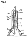
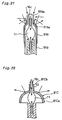
- Fig. 2 is an enlarged sectional view illustrating a main part of the discharge lamp 10 shown in Fig. 1.
- the opening 13b of the arc tube 11 is sealed with the electrode member 15.
- the electrode member 15 includes a sealing base element 15a that is fitted in the opening 13b, a lead element 15b that is arranged to run from an end of the sealing base element 15a to the hollow chamber 12a through the narrow tubular chamber 13a, and an electrode element 15c that is disposed on a free end of the lead element 150.
- the sealing base element 15a also works as a terminal connected to an outside lead wire (not shown) and receives a supply of electricity through the connection with the outside lead wire.
- the lead element 15b is apart from the inner wall face of the small-diametral portion 13 by a predetermined space and passes through the center of the narrow tubular chamber 13a along the axis thereof.
- the electrode element 15c is connected to the free end of the lead element 150 and wound in coil thereon, so that there is a discharge between the electrode element and the opposed electrode element 15c via a certain discharge distance.
- the following materials may be used for the electrode member 15.
- the materials having thermal expansion coefficients that are approximately equal to the thermal expansion coefficient of the material for the arc tube 11 are applicable for the sealing base element 15a: for example, matals like Nb and Re, alloys like Nb-Zr, and cermets like a metal-B system, a metal-C(N) system, and a metal-Si system. W, Mo, and other similar elements having high melting points are applicable for the lead element 15b and the electrode element 15c.
- a sealing glass 16a is interposed between the sealing base element 15a of the electrode member 15 and the inner wall face of the opening 13b, in order to make the arc tube 11 air-tight to the outside.
- a variety of compounds such as an SiO 2 -Al 2 O 3 -MgO system, an Al 2 O 3 -CaO-Y 2 O 3 , system, and an Al 2 O 3 -SiO 2 -Dy 2 O 3 system, are applicable for the sealing glass 16a by taking into account the thermal expansion coefficient and other physical properties of the material for the arc tube 11.
- the following method may be applied to make a seal with the sealing glass 16a.
- the method inserts the electrode member 15 into the arc tube 11 through the opening 13b.
- the method places a glass ring (not shown), which forms the sealing glass 16a, on the free end of the opening 13b and exposes the glass ring to an atmosphere of Ar gas.
- the method subsequently irradiates the glass ring with infrared emission, in order to heat and fuse the glass ring.
- the fused glass ring runs into a gap between the inner wall face of the opening 13b and the sealing base element 15a and solidifies. This enables the gap between the inner wall face of the opening 13b of the arc tube 11 and the outer circumference of the sealing base element 15a to be sealed with the sealing glass 16a.
- the emission of the discharge lamp 10 and its temperature distribution are discussed below.
- arc discharge occurs between the electrode elements 15c,15c.
- Hg vaporizes in an early stage of the arc discharge to heighten the vapor pressure in the arc tube 11.
- the increase in vapor pressure fulfills the condition required for emission of the other luminescent substances like Dy.
- the other luminescent substances like Dy excite to the ion state to cause the arc discharge.
- the shape of the electric arc is substantially elliptical.
- This shape of the electric arc results in a temperature distribution in the arc tube 11 as shown in the graph of Fig. 3.
- the temperature distribution has a substantially elliptical shape, where the temperature is about 5,000 K in a central area of the arc and gradually decreases with an increase in distance apart from the central area.
- the discharge lamp 10 has a configuration discussed below in order to enhance the emission efficiency of the arc tube 11 under such conditions.
- Fig. 4 shows dimensions of the respective constituents of the discharge lamp 10.
- the large-diametral portion 12 has a length L1 and an inner diameter D1
- the small-diametral portion 13 has a length L2 and an inner diameter D2.
- K1 defines a position of the electrode element 15c in the hollow chamber 12a and namely denotes a length from the joint of the small-diametral portion 13 with the large-diametral portion 12 to the electrode element 15c.
- K2 denotes a length from the joint to an inner end of the sealing base element 15a
- K3 denotes a length sealed with the sealing glass 16a.
- Fig. 10 is an enlarged sectional view illustrating a sealing base element 15Da, which is part of an electrode member 15D of a discharge lamp.
- Fig. 11 is an enlarged sectional view showing the surface of the sealing base element 15Da.
- the sealing base element 15Da is a columnar member mainly made of a Nb-Zr alloy and has an insertion aperture 15Dc formed on one end thereof.
- a lead element 15Db is fitted in and fixed by the insertion aperture 15Dc.
- a film layer 1500 is formed around the circumference of the sealing base element 15Da.
- the film layer 15Dd is formed by laying a thin film layer 15Df upon a buffer layer 15De.
- the thin film layer 15Df is made of W having the resistance to halide and has the thickness of 2 ⁇ m.
- the buffer layer 15De has durability against the heat cycle (ordinary temperature to 1000°C) with regard to the joint of the sealing base element 15Da with the thin film layer 15Df.
- the buffer layer 15De has the thickness of about 3 ⁇ m.
- Part of the buffer layer 15De closer to the sealing base element 15Da contains a greater ratio of the Nb-Zr alloy, and another part of the buffer layer 15De closer to the thin film layer 15Df contains a greater ratio of W. Namely the ratio of W in the buffer layer 15De gradually increases from the part near to the sealing base element 15Da to the part near to the thin film layer 15Df.
- this configuration Since the buffer layer 15De and the thin film layer 15Df are laid upon the sealing base element 15Da, and the thin film layer 15Df having the resistance to halide is formed as the outer-most layer of the sealing base element 15Da, this configuration has the corrosion resistance to the halogen-containing luminescent substances and thereby the excellent durability.
- the buffer layer 15De has the composition in which the concentration of W gradually increases.
- the inner side of the buffer layer 15De accordingly has a thermal expansion coefficient close to that of the sealing base element 15Da, whereas the outer side of the buffer layer 15De has a thermal expansion coefficient close to that of the thin film layer 15Df.
- the thin film layer 15Df and the buffer layer 15De have the thicknesses that facilitate the continuous variation of the thermal expansion coefficient.
- the thin film layer 15Df is not greater then 2 ⁇ m in thickness
- the buffer layer 15De is not greater than 3 ⁇ m in thickness.
- Addition of La2O3 to the sealing glass 16Df is preferable in order to enhance the adhesive strength of the thin film layer 15Df to the sealing glass 16Df.
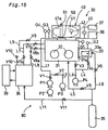
- FIG. 12 is a sectional view illustrating the heating oven 100.
- the heating oven 100 has a space for accommodating a sealing vessel 102 therein.
- the sealing vessel 102 is closed in a sealing state by a cover 104.
- a support table 106 having a plurality of support holes 106a is installed in a bottom portion of the sealing vessel 102.
- the thin film forming process proceeds in the following manner with the heating oven 100. While the cover 104 is open, support pins 108 are inserted into the support holes 106a formed in the support table 106. The upper portions of the support pins 108 are fitted into the insertion apertures 15Dc of the sealing base elements 15Da, so that the sealing base elements 15Da are supported on the support table 106 via the support pins 108.
- the sealing vessel 102 is evacuated with a non-illustrated vacuum pump to have an atmosphere of 10 -6 Torr in degree of vacuum.
- the atmosphere in the heating oven 100 is subsequently heated to the temperature of not lower than 1500°C and kept at the temperature for two hours.
- This heat treatment vaporizes part of the W powder in the powdery tungsten layer 110, and causes the Nb-Zr alloy of the sealing base element 15Da to be impregnated with the W vapor.
- the temperature of the atmosphere in the heating oven 100 is gradually decreased from 1500°C to 1400°C in six hours, so that the thin film layer 15Df is formed.
- the above heat treatment causes the buffer layer 10De including dispersion of W to be formed on the surface of the sealing base element 15Da and the thin film layer 15Df having the continuous variation in W concentration to be further formed on the thin film layer 15Df.
- the buffer layer 15De and the thin film layer 15Df are densely formed on the surface of the sealing base element 15Da including the insertion aperture 15Dc.
- the sealing base element 15Da is made of not a Nb simple body of 100% by weight but a Nb alloy, because of the following reason. Nb of 100% by weight re-crystallizes in the high temperature range of not lower then 1400°C and lowers the mechanical strength when applied for the sealing base element 15Da.
- the Nb-Zr alloy is accordingly applied for the sealing base element 15Da, in order to prevent re-crystallization in the course of the heat treatment at the temperatures of not lower than 1400°C.
- the pre-treatment may expose the sealing base element 15Da to an atmosphere of Nb vapor or an atmosphere of Nb-Zr mixed vapor. Such pre-treatment enhances the adhesion of the Nb-Zr component of the sealing base element 15Da to the W component of the thin film layer 15Df.
- Fig. 13 is a sectional view showing the state before the discharge lamp 10 is sealed.
- the opening 13b of the arc tube 11 is sealed by heating and fusing a glass ring 16c.
- the glass ring 16c contains an infrared-absorbing substance.
- Typical examples of the infrared-absorbing substance include oxides of rare earth elements, such as CeO 2 (pale yellow), Sm 2 O 3 (pale pink), HoO 3 (pale pink), Dy 2 O 3 (pale yellow); Er 2 O 3 (pink), and Nd 2 O 3 (bluish purple).
- the colored glass ring 16c is prepared by mixing one of the oxides of rare earth elements with the Al 2 O 3 -SiO 2 glass.
- Fig. 14 shows the compositions and colors of various glass rings 16c and the results of the sealing process with the glass rings 16c.
- the condition of the sealing process applied here was that the glass ring 16c irradiated with the infrared emission was kept at the temperature of 1500°C for 30 seconds.
- the results of the sealing process were evaluated as the flow length of the fused glass ring 16c flown into the gap between the arc tube 11 and the sealing base element 15a.
- a glass ring containing Y2O3 was also evaluated as a comparative example. While the prior art composition required the heating time of about one minute for sealing, the compositions of this embodiment shortened the required heating time to about 30 seconds.
- the infrared-absorbing substance may be mixed with a coating material, which is applied onto the surface of the glass ring 16c, instead of being directly mixed with the primary constituent of the glass ring 16c.
- Fig. 31 shows the structure of another discharge lamp 10F in another embodiment according to the present invention and its temperature distribution.
- the discharge lamp 10F has a large-diametral portion 12F and a pair of small-diametral portions 13F.
- the small-diametral portion 13F has a low heat conduction part 13Fa, which is made of a specific material having a lower thermal conductivity than that of the large-diametral portion 12F.
- the sealing base element 15a of the electrode member 15 is supported on the low heat conduction part 13Fa via the sealing glass 16a.
- the low heat conduction part 13Fa may be prepared by sticking the specific material with the large-diametral portion or alternatively casting the specific material in the casting process.
- the low heat conduction part 13Fa in the small-diametral portion 13F is ascribed to the following reason.
- Application of the translucent material having a large thermal conductivity for the large-diametral portion 12F heightens the coolest part temperature Tcs in the large-diametral portion 12F and improves the emission efficiency of the discharge lamp 10F as discussed previously.
- the rise of the coolest part temperature Tcs leads to a temperature rise of the glass end 16b of the sealing glass 16a
- the low heat conduction part 13Fa solves this problem.
- a curve Ta represents a temperature variation in the end of the large-diametral portion 12F and part of the small-diametral portion 13F extended from the large-diametral portion 12F.
- a curve To represents a temperature variation in the low heat conduction part 13Fa of the small-diametral portion 13F.
- the temperature gradient of the curve Tb is greater than the temperature gradient of the curve Ta. Even when the coolest part temperature Tcs rises during the emission of the discharge lamp 10F, the large temperature gradient of the curve Tb readily causes the temperature on the glass end 16b of the sealing glass 16a to be lower than the glass transition temperature Tg.
- the low heat conduction part 13Fa reduces the temperature of the sealing glass 16a even under the condition of the high emission temperature in the discharge lamp 10F.
- a ring-shaped heat-insulator 13Fb containing, for example, Al 2 O 3 may be interposed between the narrow tubular chamber 13a and the glass end 16b, in order to prevent the temperature rise of the glass end 16b of the sealing glass 16a due to the conducted heat, in which the large-diametral portion 12F is conducted to the narrow tubular chamber 13a of the small-diametral portion 13F.
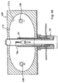
- Fig. 15 schematically illustrates a discharge lamp sealing apparatus 30 for sealing the end of the arc tube 11
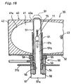
- Fig. 16 is an enlarged sectional view illustrating a main part of the discharge lamp sealing apparatus 30 shown in Fig. 15.
- the discharge lamp sealing apparatus 30 includes an operation box 31, a pass box 33, a heating unit 40, a feeding mechanism 50, and a pumping mechanism 80.
- the operation box 31 has a pair of operation gloves 32,32 on the front face thereof, which receive the hands of the user therein. The user can carry out the required operations in an air-tight manner with the pair of operation gloves 32,32.
- the pass box 33 is located adjacent to the operation box 31.
- the pass box 33 is continuous with the operation box 31 across a door 31a.
- the user can feed a variety of supplies delivered into the pass box 33 with the pair of operation gloves 32,32.
- the pass box 33 has a door 33a that is open to the outside. The user can deliver a variety of supplies and materials into the pass box 33 while the door 33a is open.
- the heating unit 40 is disposed above the operation box 31 across a support plate 52 as shown in Fig. 16.
- the heating unit 40 includes a casing 42 for defining a heating chamber 41 and an infrared lamp 43 located in the heating chamber 41.
- a reflecting plane 41a having the function of reflecting the infrared radiation is formed to face the heating chamber 41.
- the reflecting plane 41a is a concave mirror that reflects the infrared radiation from the infrared lamp 43 and condenses the reflected infrared radiation to a light condensing area.
- the reflecting plane 41a is obtained by covering the casing 42 with a metal like platinum, gold, or nickel according to the method of spray coating or sputtering.
- the reflecting plane 41a is arranged to be cooled down by a non-illustrated cooling unit.
- the feeding mechanism 50 is disposed below the heating unit 40.
- the feeding mechanism 50 moves the arc tube 11 from the operation box 31 and exposes the arc tube 11 in an air-tight manner to the light condensing area in the beating chamber 41.
- the feeding mechanism 50 includes a feeding conduit 51 mainly made of quartz glass, an upper fixture 53 that is disposed on the top face of the operation box 31 to support the feeding conduit 51, a lower fixture 54 that is screwed to the upper fixture 53 to clamp a top plate 31b of the operation box 31, a sealing member 55 that is interposed between the upper fixture 53 and the feeding conduit 51, and a nut 58 that is jammed to seal the gap between the upper fixture 53 and the feeding conduit 51 with the sealing member 55.
- a feed hole 56 is formed to run through the lower fixture 54 and the upper fixture 53, and a support jig 57 is inserted into and removed from the feed hole 56.
- the support jig 57 includes a flange 57a that is in contact with the bottom face of the lower fixture 54 via an O ring 59 and a support 57b that is extended upright from the flange 57a.
- a support aperture 57c is formed in the upper end of the support 57b in order to support one end of the arc tube 11.
- the support jig 57 is designed to be freely lifted up and down through the feeding conduit 51.
- the mechanism for lifting up and down the support jig 57 may be manual, power-driven or pneumatic.
- An infrared shield 61 is disposed around the feeding conduit 51.
- the infrared shield 61 is a tubular body that is made of Pt and reflects the infrared radiation, in order to cause the infrared radiation to enter only the upper portion of the arc tube 11.
- the infrared shield 61 is extended upright to a position that is a little lower than the height of the electrode member 15 of the arc tube 11.
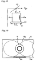
- Fig. 17 is a side view schematically illustrating the heating unit 40
- Fig. 18 is a top view illustrating the heating unit 40.
- an X-axis rail R1 and a Y-axis rail R2 are laid below the heating unit 40.
- the X-axis rail R1 and the Y-axis rail R2 are arranged to be perpendicular to each other on the horizontal surface and support the heating unit 40 to enable the movement thereof.
- the heating unit 40 is thus moveable to an arbitrary position in the horizontal direction.
- the structure for enabling the user to observe the sealing state of the arc tube 11 located in the feeding conduit 51 includes a mirror Mr located above and on the center of the heating unit 40 and a transparent window 42a disposed on the side face of the heating unit 40 as shown in Fig. 18.
- the pumping mechanism 80 of the discharge lamp sealing apparatus 30 includes a turbo pump P1 and rotary pumps P2, P3, and P4.
- the turbo pump P1 gives the high degree of vacuum (10 -5 to 10 -7 Torr).
- the rotary pump P2 is connected to the turbo pump P1 in series to ensure the smooth operation at the start of the turbo pump P1.
- the rotary pumps P3 and P4 give the low degree of vacuum (about 10 -1 Torr).
- the turbo pump P1 is connected to the feeding conduit 51 via a piping L1 with a valve V1.
- the rotary pump P3 is connected to the piping L1 via a piping L2 with a valve V2.
- the rotary pump P4 is connected to the operation box 31 via a piping L3 with a valve V3 and further to the pass box 33 via a piping L4 with a valve V4.
- the pressure in the operation box 31 is measured with a pressure gauge G1, the pressure in the pass box 33 with a pressure gauge G2, and the pressure in the feeding conduit 51 with pressure gauges G3 and G4 attached to the piping L1.
- the two pressure gauges G3 and G4 are used for measuring the pressure in the feeding conduit 51, in order to extend the measurable range, since the pressure in the feeding conduit 51 drastically varies.
- An oxygen analyzer 37 and a moisture meter 38 are attached to the operation box 31.
- a gas circulation and purification unit 36 is located adjacent to the operation box 31.
- a cooling unit 39 is attached to the gas circulation and purification unit 36.
- the gas circulation and purification unit 36 is connected to the operation box 31 via a supply piping L7 with valves V7a and V7b and a return piping L8 with valves V8a and V8b.
- the supply piping L7 branches off to a piping L9 with a valve V9, which joins the piping L1 leading to the feeding conduit 51.
- the gas circulation and purification unit 36 feeds a supply of Ar gas into the operation box 31 via the supply piping L7 and receives a returned supply of Ar gas via the return piping L8.
- the gas circulation and purification unit 36 removes oxygen from the returned supply of Ar gas through a catalytic reaction and makes the dew point not higher than -70°C and the concentration of the residual oxygen not greater than 0.01 ppm in the operation box 31. This effectively prevents the deterioration of the performance of the discharge lamp.
- the gas circulation and purification unit 36 is connected to a piping L10 with a valve V1 and also to a piping L11 with a valve V11. Feeding several drops of a alcohol into the gas circulation and purification unit 36 via the piping L10 reduces the concentration of the residual oxygen in the gas circulation and purification unit 36.
- a supply of Ar working as a cooling medium is fed from an Ar tank 35 to a molecular tube via the piping L11.
- the process first closes the door 31a between the pass box 33 and the operation box 31 shown in Fig. 15 and opens the door 33a of the pass box 33 to be continuous with the outside.
- a variety of supplies and materials that is, luminescent substances like mercury and iodide and the arc tube 11, are fed into the pass box 33 through the open door 33a.
- the arc tube 11 has one end that is sealed with the electrode member 15 having an electrode and the other end that is kept open.
- the process subsequently closes the door 33a between the pass box 33 and the outside, opens the valve V4, reduces the pressure in the pass box 33 with the rotary pump P4, opens the valve V6, and replaces the reduced atmosphere in the pass box 33 with gaseous Ar.
- the process then opens the door 31a between the pass box 33 and the operation box 31 and feeds the variety of supplies, which have been delivered to the pass box 33, into the operation box 31 with the operation gloves 32,32.
- the operation box 31 is filled in advance with gaseous Ar and set at approximately one atmospheric pressure.
- the process subsequently closes the door 31a between the pass box 33 and the operation box 31.
- the process inserts the lower end of the arc tube 11, which has been sealed with the electrode member 15, into the support aperture 57c of the support jig 57. This causes the arc tube 11 to be supported on the support jig 57 in the upright manner.
- the process subsequently injects the weighed luminescent substances into the arc tube 11 via the open upper end thereof.
- the process then inserts the electrode member 15 having an electrode into the open upper end of the arc tube 11 and sets the glass ring 16a on the circumference of the open upper end of the arc tube 11, in which the electrode member 15 is fitted, as shown in Fig. 19.
- the process lifts the support jig 57 up, so as to insert the arc tube 11 supported on the support jig 57 into the feeding conduit 51 (in the state of Fig. 16).
- the position of the glass ring 16c is adjusted to the light condensing area of the infrared radiation.
- the detailed process of positioning the glass ring 16c to the light condensing area finely adjusts the position of the support jig 57 in the vertical direction based on the observation through the transparent window 42a, and moves the heating unit 40 on the X-axis rail R1 and the Y-axis rail R2 in the horizontal direction based on the observation with the error Mr as shown in Figs. 17 and 18. This procedure enables the vertical position of the sealing glass 16a to he securely adjusted to the light condensing area of the infrared radiation.
- the process opens the valve V1 in this state, while the valves V2 and V9 are kept closed.
- the gaseous Ar is removed from the feeding conduit 51 with the turbo pump P1 to the pressure of 10 -1 to 10 -7 Torr.
- the process then opens the valve V9 while the valves V1 and V2 are closed, and feeds a supply of gaseous Ar into the feeding conduit 51 to the pressure of 30 to 300 Torr.
- the process turns the infrared lamp 43 on and makes the infrared radiation reflected from the reflecting plane 41a, so that the infrared radiation is condensed on the glass ring 16c to fuse the glass ring 16c.
- the supply of gaseous Ar increases the pressure in the feeding conduit 51 to approximately 500 Torr.
- the pressure difference enables the fused glass ring 16c to flow into the gap between the electrode member 15 and the arc tube 11.
- the process stops heating when the flow of fused glass reaches a predetermined position, based on the observation with naked eyes. This arrangement enables the gap between the opening of the arc tube 11 and the electrode member 15 to be sealed with the sealing glass 16a.
- the flow length of the fused glass may be measured automatically with a sensor, instead of being observed with naked eyes.
- the infrared shield 61 disposed around the feeding conduit 51 causes only the periphery of the sealing glass 16a to be heated, while protecting the residual part of the arc tube 11 from heat, this structure does not cause an unfavorable temperature rise in the arc tube 11 and prevents the luminescent substances from flying out of the arc tube 11.
- the fused sealing glass 16a Since the fused sealing glass 16a is exposed to the pressure difference between the inside and the outside of the arc tube 11, when flowing into the gap between the electrode member 15 and the opening of the arc tube 11.
- the pressure difference enables the fused sealing glass 11 to be smoothly flown into even a very narrow gap.
- the flow length of the sealing glass 16a is readily regulated by adjusting the pressure difference.
- an opening 40a is formed in the upper face of the heating unit 40 in order to receive the upper end of the feeding conduit 51.
- the upper end of the feeding conduit 51 is projected from the opening 40a. It is preferable that the feeding conduit 51 has the length that is projectable from the opening 40a.
- Fig. 21 is a sectional view illustrating another feeding conduit 51B in another embodiment according to the present invention.
- An upper end portion of the feeding conduit 51B forms a narrow tubular part 51Ba as shown in Fig. 21.
- An infrared shield 61B is designed to set on an upper portion of the feeding conduit 51B.
- the infrared shield 61B has a narrow diametral portion 61Ba, in which the narrow tubular part 51Ba is fitted.
- the narrow tubular portion 61Ba of the infrared shield 61B is closer to the glass ring 16c set on the arc tube 11, the light condensing area heated with the infrared radiation is restricted to a narrow area on the upper end portion of the arc tube 11. This arrangement further prevents the residual part of the arc tube 11 from being unnecessarily heated and thereby prevents the luminescent substances from flying out of the arc tube 11.
- Fig. 22 is a sectional view illustrating the arc tube 11 in still another embodiment according to the present invention.
- An infrared shield 61C is set on the upper small-diametral portion 13 of the arc tube 11 as shown in Fig. 22.
- the infrared shield 61C includes a dome section 61Ca to cover the large-diametral portion 12 and a tubular support section 61Cb integrally formed with and disposed above the dome section 61Ca.
- the upper small-diametral portion 13 is fitted in and supported by the tubular support section 61Cb.
- Fitting the upper small-diametral portion 13 into the tubular support section 61Cb causes the infrared shield 61C to be set on the upper portion of the arc tube 11.
- the dome section 61Ca of the infrared shield 61C is designed to be greater than and cover the large-diametral portion 12.
- the infrared shield 61C is accordingly applicable for a variety of arc tubes 11 with different sizes of the large diametral portion 12.
- the infrared shield 61C is directly set on the upper portion of the arc tube 11. This arrangement enables only a sufficiently narrow area to be irradiated with infrared emission and ensures the sealing with the glass ring 16c.
- Fig. 23 is a sectional view illustrating a upper portion of another feeding conduit 51D in another embodiment according to the present invention.
- a support jig 570 and a sealed tube 71 are placed in the feeding conduit 51D as shown in Fig. 23.
- the sealed tube 71 is placed on the support jig 57D and includes a cylindrical body 71a and a suspension jig 71b for sealing an upper opening of the cylindrical body 71a.
- the cater of the suspension jig 71b suspends the upper end of the electrode member 15 fitted in the opening 13b of the arc tube 11.
- the sealing process with the support jig 57D and the sealed tube 71 first inserts one end of the arc tube 11 into the support aperture 57a of the support jig 57D in the operation box 31 (see Fig. 15). After the electrode member 15 with the glass ring 16c set thereon is attached to the suspension jig 71b, the suspension jig 71b is set in the upper opening of the cylindrical body 71a. The sealed tube 71 is then placed on the support jig 57D. At this moment, the lower end of the electrode member 15 is inserted into the opening 13b of the arc tube 11. This process causes the electrode member 15 to be suspended by the suspension jig 71b.
- the sealing process is then carried out to seal the electrode member 15 in this state.
- Using the support jig 57D and the sealed tube 71 enables the electrode member 15 to be securely welded to a specified position of the opening 13b of the arc tube 11 without causing a downward positional deviation of the electrode member 15 due to the fusion of the glass ring 16c.
- Fig. 24 is a sectional via illustrating the upper portion of the feeding conduit 51 in still another embodiment according to the present invention.
- a getter 72 is located around the upper end of the support jig 57 inside the feeding conduit 51 as shown in Fig. 24.
- the getter 72 adsorbs and removes impurities in the feeding conduit 51.
- the getter 72 removes the impurities, which have entered the feeding conduit 51 in the sealing process, and thereby prevents the inside of the arc tube 11 from being contaminated with the impurities.
- a quartz outer tube 73 may be disposed outside the feeding conduit 51 via a certain space, in which a getter 72B is located.
- the outer tube 73 functions as a barrier that prevents impurities from entering the feeding conduit 51, while the getter 72B adsorbs and removes the impurities. This structure further prevents the inside of the arc tube 11 from being contaminated with impurities.
- the support 57Jc of the support jig 57J which covers the arc tube 11 supported by the support recess 57Je, shields the infrared radiation and prevents a temperature rise in the arc tube 11, thereby enabling only a periphery of the glass ring 16c set on the arc tube 11 to be heated.
- the heat of the infrared reflector 61J is mostly conducted to the support base 57Jb that is made of a metal having a high thermal conductivity and hardly conducted to the support 57Jc that is made of Al 2 O 3 having a low thermal conductivity.
- the support 57Jc for supporting the arc tube 11 does not accordingly have high temperatures. This arrangement effectively prevents a temperature rise in the arc tube 11.
- the infrared lamp 43 placed in the heating chamber 41 of the heating unit 40 shown in Fig. 16 may be located at any position that enables part of the arc tube 11 in the feeding conduit 51 to be heated in a homogeneous manner.
- a variety of other configurations are applicable as shown in Figs. 29 and 30.
- a pre-treatment discussed below is performed to remove the impurities adhering to the surface of the supplies including the arc tube 11 and the electrode member 15 when these supplies including the arc tube 11 and the electrode member 15 are fed into the operation box 31 in the example of Figs. 15 and 16.
- the support jig 57 is lifted up while the arc tube 11 is supported on the support jig 57. This seals the arc tube 11 in the feeding conduit 51.
- the infrared shield 61 is lowered to the position that does not cover the arc tube 11, the supply of electricity to the infrared lamp 43 is gradually increased to raise the temperatures in the feeding conduit 51 and in the arc tube 11.
- the pre-treatment may be performed with the same heating unit 40 or with another heating unit located adjacent to the heating unit 40. In the latter case, the pre-treatment and the series of the processing in the sealing process can be carried out in a continuous manner. This ensures the excellent productivity.
- the discharge lamp of the present invention has a high luminance and is thus applicable for a light source of projection televisions.
Landscapes
- Engineering & Computer Science (AREA)
- Manufacturing & Machinery (AREA)
- Vessels And Coating Films For Discharge Lamps (AREA)
Applications Claiming Priority (7)
| Application Number | Priority Date | Filing Date | Title |
|---|---|---|---|
| JP3968697 | 1997-01-18 | ||
| JP3968697A JPH10208639A (ja) | 1997-01-18 | 1997-01-18 | 赤外線封止装置 |
| JP9072697 | 1997-04-09 | ||
| JP09072697A JP3620211B2 (ja) | 1997-04-09 | 1997-04-09 | ランプの封止装置 |
| JP21589097 | 1997-07-26 | ||
| JP9215890A JPH1145682A (ja) | 1997-07-26 | 1997-07-26 | ランプ、導電性材料及びその製造方法 |
| PCT/JP1998/000158 WO1998032147A1 (fr) | 1997-01-18 | 1998-01-16 | Lampe a decharge, procede de fermeture etanche d'une lampe a decharge et dispositif de fermeture etanche pour lampe a decharge |
Publications (2)
| Publication Number | Publication Date |
|---|---|
| EP0954007A1 true EP0954007A1 (de) | 1999-11-03 |
| EP0954007A4 EP0954007A4 (de) | 2000-07-19 |
Family
ID=27290228
Family Applications (1)
| Application Number | Title | Priority Date | Filing Date |
|---|---|---|---|
| EP98900405A Withdrawn EP0954007A4 (de) | 1997-01-18 | 1998-01-16 | Entladungslampe verfahren und vorrichtung zur abdichtung einer entladungslampe |
Country Status (3)
| Country | Link |
|---|---|
| US (1) | US6354901B1 (de) |
| EP (1) | EP0954007A4 (de) |
| WO (1) | WO1998032147A1 (de) |
Cited By (8)
| Publication number | Priority date | Publication date | Assignee | Title |
|---|---|---|---|---|
| EP1160831A1 (de) * | 2000-05-30 | 2001-12-05 | Japan Storage Battery Co., Ltd. | Entladungslampe |
| WO2002049074A1 (en) * | 2000-12-14 | 2002-06-20 | Koninklijke Philips Electronics N.V. | High pressure discharge lamp |
| WO2002071442A1 (en) * | 2000-11-06 | 2002-09-12 | General Electric Company | Ceramic discharge chamber for a discharge lamp and methods of making it |
| EP0935278A4 (de) * | 1997-07-25 | 2002-10-09 | Toshiba Lighting & Technology | Hochspannungs-entladungslampe, hochspannungsentladungslampen vorrichtung, und leuchtvorrichtung |
| US6620272B2 (en) | 2001-02-23 | 2003-09-16 | Osram Sylvania Inc. | Method of assembling a ceramic body |
| EP1612841A2 (de) | 2004-06-30 | 2006-01-04 | Osram Sylvania Inc. | Keramisches Entladungsgefäss mit integriertem induktivem Heizelement |
| US7189131B2 (en) | 2001-02-23 | 2007-03-13 | Osram Sylvania Inc. | High buffer gas pressure ceramic arc tube and method and apparatus for making same |
| WO2008119697A1 (de) * | 2007-03-30 | 2008-10-09 | Osram Gesellschaft mit beschränkter Haftung | Hochdruckentladungslampe |
Families Citing this family (16)
| Publication number | Priority date | Publication date | Assignee | Title |
|---|---|---|---|---|
| JP2002012432A (ja) * | 2000-06-27 | 2002-01-15 | Toshiba Mach Co Ltd | ガラス製光学素子の成形装置 |
| US6922017B2 (en) * | 2000-11-30 | 2005-07-26 | Matsushita Electric Industrial Co., Ltd. | Infrared lamp, method of manufacturing the same, and heating apparatus using the infrared lamp |
| US20030164894A1 (en) * | 2001-04-05 | 2003-09-04 | Chuan-Yu Hsu | Optical chassis of plating film reflection and its manufacturing procedure |
| DE20112599U1 (de) * | 2001-08-01 | 2002-12-19 | Kronospan Tech Co Ltd | MDF-Platte nebst Herstellung |
| US6669521B2 (en) * | 2001-09-26 | 2003-12-30 | Osram Sylvania Inc. | Method of removing contaminants from a double-ended arc discharge tube |
| JP2004079323A (ja) * | 2002-08-16 | 2004-03-11 | Fuji Photo Film Co Ltd | 放電管の製造方法 |
| US6832943B2 (en) * | 2002-11-14 | 2004-12-21 | General Electric Company | Heat shield design for arc tubes |
| DE10315161A1 (de) * | 2003-04-02 | 2004-10-14 | Mettler-Toledo Gmbh | Verfahren und Vorrichtung zur Herstellung von Glaskörpern sowie Glaskörper und Messsonde |
| US7159990B2 (en) * | 2003-08-18 | 2007-01-09 | Seiko Epson Corporation | Method of manufacturing reflective mirror, illumination device, and projector |
| US7404496B2 (en) * | 2005-06-20 | 2008-07-29 | Osram Sylvania Inc. | Green-state ceramic discharge vessel parts |
| US20070138931A1 (en) * | 2005-12-19 | 2007-06-21 | General Electric Company | Backwound electrode coil for electric arc tube of ceramic metal halide lamp and method of manufacture |
| US20070138963A1 (en) * | 2005-12-19 | 2007-06-21 | General Electric Company | Ceramic arc chamber having shaped ends |
| CN101506932B (zh) | 2006-08-18 | 2012-07-04 | 皇家飞利浦电子股份有限公司 | 金属卤化物灯 |
| CN101916711B (zh) * | 2010-08-06 | 2013-04-10 | 杨潮平 | 一种陶瓷金卤灯泡壳 |
| DE102011115841A1 (de) * | 2010-11-19 | 2012-05-24 | Heraeus Noblelight Gmbh | Bestrahlungsvorrichtung |
| CN102324357A (zh) * | 2011-09-21 | 2012-01-18 | 广州威理照明科技有限公司 | 一种陶瓷金卤灯管的封接设备及方法 |
Citations (8)
| Publication number | Priority date | Publication date | Assignee | Title |
|---|---|---|---|---|
| FR885734A (fr) * | 1941-09-11 | 1943-09-23 | Patent Treuhand Ges Fu R Elek | Lampe électrique à décharge gazeuse à haute pression |
| US3716285A (en) * | 1971-08-18 | 1973-02-13 | Westinghouse Electric Corp | Method of manufacturing subminiature electric lamps |
| US4147952A (en) * | 1974-12-12 | 1979-04-03 | Gte Sylvania Incorporated | Method of sealing alumina arc tube |
| EP0011993A1 (de) * | 1978-12-01 | 1980-06-11 | Thorn Emi Plc | Elektrische Entladungslampen |
| GB2036420A (en) * | 1978-12-01 | 1980-06-25 | Thorn Electrical Ind Ltd | Electric Discharge Lamps |
| US4214885A (en) * | 1978-03-01 | 1980-07-29 | Hideo Nishi | Method for producing miniature lamps |
| JPS5889756A (ja) * | 1981-11-24 | 1983-05-28 | Toshiba Corp | 放電灯用発光管の電極封着装置 |
| JPS6069460U (ja) * | 1983-10-19 | 1985-05-16 | 株式会社東芝 | 金属蒸気放電灯 |
Family Cites Families (13)
| Publication number | Priority date | Publication date | Assignee | Title |
|---|---|---|---|---|
| US3518411A (en) * | 1968-01-17 | 1970-06-30 | Clare & Co C P | Infrared heating apparatus for sealing reed switches |
| US3628846A (en) * | 1970-03-01 | 1971-12-21 | Duro Test Corp | Method of making a vapor discharge lamp |
| US4158485A (en) * | 1975-02-10 | 1979-06-19 | Siemens Aktiengesellschaft | Liquid crystal cell with a glass solder seal |
| GB1592508A (en) * | 1976-12-07 | 1981-07-08 | Tokyo Shibaura Electric Co | Method for manufacturing a luminous tube for discharge lamp |
| JPS53135037A (en) * | 1977-04-28 | 1978-11-25 | Nichiden Kikai Kk | Heating apparatus |
| EP0055532B1 (de) * | 1980-12-20 | 1984-09-26 | Thorn Emi Plc | Verfahren zur Herstellung von Bogenentladungslampen und mittels dieses Verfahrens hergestellte Bogenentladungslampe |
| JPS6069460A (ja) | 1983-09-27 | 1985-04-20 | 株式会社東芝 | 冷凍装置 |
| US4689031A (en) * | 1984-05-31 | 1987-08-25 | Gte Products Corporation | Method for sealing arc discharge lamps |
| JPH01213953A (ja) * | 1988-02-23 | 1989-08-28 | Ushio Inc | 高圧放電灯用電極 |
| US5188554A (en) * | 1988-05-13 | 1993-02-23 | Gte Products Corporation | Method for isolating arc lamp lead-in from frit seal |
| DE4037721C2 (de) * | 1990-11-27 | 2003-02-13 | Patent Treuhand Ges Fuer Elektrische Gluehlampen Mbh | Verfahren zur Herstellung einer Natriumhochdrucklampe sowie dafür geeignete Vorrichtung |
| KR100396233B1 (ko) * | 1995-03-09 | 2003-11-01 | 코닌클리케 필립스 일렉트로닉스 엔.브이. | 고압방전램프 |
| US6351282B1 (en) * | 1997-09-02 | 2002-02-26 | Intel Corporation | Method and apparatus for taking digital pictures with an industry standard film camera |
-
1998
- 1998-01-16 US US09/341,788 patent/US6354901B1/en not_active Expired - Fee Related
- 1998-01-16 WO PCT/JP1998/000158 patent/WO1998032147A1/ja not_active Application Discontinuation
- 1998-01-16 EP EP98900405A patent/EP0954007A4/de not_active Withdrawn
Patent Citations (8)
| Publication number | Priority date | Publication date | Assignee | Title |
|---|---|---|---|---|
| FR885734A (fr) * | 1941-09-11 | 1943-09-23 | Patent Treuhand Ges Fu R Elek | Lampe électrique à décharge gazeuse à haute pression |
| US3716285A (en) * | 1971-08-18 | 1973-02-13 | Westinghouse Electric Corp | Method of manufacturing subminiature electric lamps |
| US4147952A (en) * | 1974-12-12 | 1979-04-03 | Gte Sylvania Incorporated | Method of sealing alumina arc tube |
| US4214885A (en) * | 1978-03-01 | 1980-07-29 | Hideo Nishi | Method for producing miniature lamps |
| EP0011993A1 (de) * | 1978-12-01 | 1980-06-11 | Thorn Emi Plc | Elektrische Entladungslampen |
| GB2036420A (en) * | 1978-12-01 | 1980-06-25 | Thorn Electrical Ind Ltd | Electric Discharge Lamps |
| JPS5889756A (ja) * | 1981-11-24 | 1983-05-28 | Toshiba Corp | 放電灯用発光管の電極封着装置 |
| JPS6069460U (ja) * | 1983-10-19 | 1985-05-16 | 株式会社東芝 | 金属蒸気放電灯 |
Non-Patent Citations (2)
| Title |
|---|
| PATENT ABSTRACTS OF JAPAN vol. 007, no. 186 (E-193), 16 August 1983 (1983-08-16) -& JP 58 089756 A (TOKYO SHIBAURA DENKI KK), 28 May 1983 (1983-05-28) * |
| See also references of WO9832147A1 * |
Cited By (10)
| Publication number | Priority date | Publication date | Assignee | Title |
|---|---|---|---|---|
| EP0935278A4 (de) * | 1997-07-25 | 2002-10-09 | Toshiba Lighting & Technology | Hochspannungs-entladungslampe, hochspannungsentladungslampen vorrichtung, und leuchtvorrichtung |
| EP1160831A1 (de) * | 2000-05-30 | 2001-12-05 | Japan Storage Battery Co., Ltd. | Entladungslampe |
| US6538379B2 (en) | 2000-05-30 | 2003-03-25 | Japan Storage Battery Co., Ltd. | Discharge lamp |
| WO2002071442A1 (en) * | 2000-11-06 | 2002-09-12 | General Electric Company | Ceramic discharge chamber for a discharge lamp and methods of making it |
| WO2002049074A1 (en) * | 2000-12-14 | 2002-06-20 | Koninklijke Philips Electronics N.V. | High pressure discharge lamp |
| US6620272B2 (en) | 2001-02-23 | 2003-09-16 | Osram Sylvania Inc. | Method of assembling a ceramic body |
| US7189131B2 (en) | 2001-02-23 | 2007-03-13 | Osram Sylvania Inc. | High buffer gas pressure ceramic arc tube and method and apparatus for making same |
| US7226334B2 (en) | 2001-02-23 | 2007-06-05 | Osram Sylvania Inc. | Apparatus for making high buffer gas pressure ceramic arc tube |
| EP1612841A2 (de) | 2004-06-30 | 2006-01-04 | Osram Sylvania Inc. | Keramisches Entladungsgefäss mit integriertem induktivem Heizelement |
| WO2008119697A1 (de) * | 2007-03-30 | 2008-10-09 | Osram Gesellschaft mit beschränkter Haftung | Hochdruckentladungslampe |
Also Published As
| Publication number | Publication date |
|---|---|
| EP0954007A4 (de) | 2000-07-19 |
| US6354901B1 (en) | 2002-03-12 |
| WO1998032147A1 (fr) | 1998-07-23 |
Similar Documents
| Publication | Publication Date | Title |
|---|---|---|
| EP0954007A1 (de) | Entladungslampe verfahren und vorrichtung zur abdichtung einer entladungslampe | |
| US5412288A (en) | Amalgam support in an electrodeless fluorescent lamp | |
| EP0646942B1 (de) | Genaue Plazierung und Halterung eines Amalgams in einer elektrodenlose Leuchtstofflampe | |
| US20060279218A1 (en) | High-pressure discharge lamp, high-pressure discharge lamp operating apparatus, and illuminating apparatus | |
| EP0330268B1 (de) | Elektrische Lampe | |
| CN1461492A (zh) | 高缓冲气体压力陶瓷电弧管及其制造方法和制造设备 | |
| US5394057A (en) | Protective metal silicate coating for a metal halide arc discharge lamp | |
| US3558963A (en) | High-intensity vapor arc-lamp | |
| JPH09185944A (ja) | 低圧水銀放電ランプの製造方法および低圧水銀放電ランプ | |
| EP1289001A2 (de) | Hochdruckentladungslampen und Verfahren zur Herstellung einer Hochdruckentladungslampe | |
| US3859555A (en) | Fluorescent lamp containing-amalgam-forming material | |
| EP0467610A2 (de) | Schutzschicht aus Berylliumoxid für Entladungslampen hoher Intensität | |
| US5489819A (en) | Method of operating a metallic vapor discharge lamp | |
| RU2155415C2 (ru) | Устройство дозированной подачи кислорода для газоразрядных ламп высокого давления | |
| CN101562117A (zh) | 防止或减少通过金属卤化物灯外壳的氦泄漏的方法 | |
| JP3320376B2 (ja) | 放電ランプおよびその製造方法 | |
| EP1607997B1 (de) | Verfahren zur herstellung einer hochdruckentladungslampe, hochdruckentladungslampe und lampeneinheit mit einer solchen hochdruckentladungslampe und bildanzeige | |
| US6814641B2 (en) | Method of manufacturing discharge lamps and a discharge lamp with a halogen introduction carrier | |
| GB2197982A (en) | Metal halide arc tube and lamp | |
| WO1999048126A1 (en) | Method of manufacturing a low-pressure mercury vapor discharge lamp | |
| JPH10312751A (ja) | セラミック製放電ランプの製造方法 | |
| JPH11354076A (ja) | 放電灯及びその封着方法 | |
| JP3620211B2 (ja) | ランプの封止装置 | |
| JPH1083793A (ja) | 高圧放電ランプおよび照明装置 | |
| JPH07192689A (ja) | 水銀蒸気放電ランプ、その製造方法ならびに照明装置 |
Legal Events
| Date | Code | Title | Description |
|---|---|---|---|
| PUAI | Public reference made under article 153(3) epc to a published international application that has entered the european phase |
Free format text: ORIGINAL CODE: 0009012 |
|
| 17P | Request for examination filed |
Effective date: 19990816 |
|
| AK | Designated contracting states |
Kind code of ref document: A1 Designated state(s): DE GB NL |
|
| RIC1 | Information provided on ipc code assigned before grant |
Free format text: 7H 01J 9/32 A, 7H 01J 9/40 B, 7H 01J 61/073 B, 7H 01J 61/30 B, 7H 01J 9/395 B |
|
| RIC1 | Information provided on ipc code assigned before grant |
Free format text: 7H 01J 9/32 A, 7H 01J 9/40 B, 7H 01J 61/073 B, 7H 01J 61/30 B, 7H 01J 9/395 B, 7H 01J 61/52 B |
|
| A4 | Supplementary search report drawn up and despatched |
Effective date: 20000603 |
|
| AK | Designated contracting states |
Kind code of ref document: A4 Designated state(s): DE GB NL |
|
| 17Q | First examination report despatched |
Effective date: 20021218 |
|
| STAA | Information on the status of an ep patent application or granted ep patent |
Free format text: STATUS: THE APPLICATION IS DEEMED TO BE WITHDRAWN |
|
| 18D | Application deemed to be withdrawn |
Effective date: 20030429 |