EP0953375A2 - Verfahren zur Verminderung des Stickoxidgehaltes der Abgase eines Verbrennungsmotors - Google Patents
Verfahren zur Verminderung des Stickoxidgehaltes der Abgase eines Verbrennungsmotors Download PDFInfo
- Publication number
- EP0953375A2 EP0953375A2 EP99108398A EP99108398A EP0953375A2 EP 0953375 A2 EP0953375 A2 EP 0953375A2 EP 99108398 A EP99108398 A EP 99108398A EP 99108398 A EP99108398 A EP 99108398A EP 0953375 A2 EP0953375 A2 EP 0953375A2
- Authority
- EP
- European Patent Office
- Prior art keywords
- nitrogen oxide
- storage material
- gas discharge
- nitrogen
- oxide storage
- Prior art date
- Legal status (The legal status is an assumption and is not a legal conclusion. Google has not performed a legal analysis and makes no representation as to the accuracy of the status listed.)
- Granted
Links
Images



Classifications
-
- F—MECHANICAL ENGINEERING; LIGHTING; HEATING; WEAPONS; BLASTING
- F01—MACHINES OR ENGINES IN GENERAL; ENGINE PLANTS IN GENERAL; STEAM ENGINES
- F01N—GAS-FLOW SILENCERS OR EXHAUST APPARATUS FOR MACHINES OR ENGINES IN GENERAL; GAS-FLOW SILENCERS OR EXHAUST APPARATUS FOR INTERNAL-COMBUSTION ENGINES
- F01N3/00—Exhaust or silencing apparatus having means for purifying, rendering innocuous, or otherwise treating exhaust
- F01N3/08—Exhaust or silencing apparatus having means for purifying, rendering innocuous, or otherwise treating exhaust for rendering innocuous
- F01N3/0807—Exhaust or silencing apparatus having means for purifying, rendering innocuous, or otherwise treating exhaust for rendering innocuous by using absorbents or adsorbents
- F01N3/0828—Exhaust or silencing apparatus having means for purifying, rendering innocuous, or otherwise treating exhaust for rendering innocuous by using absorbents or adsorbents characterised by the absorbed or adsorbed substances
- F01N3/0842—Nitrogen oxides
-
- B—PERFORMING OPERATIONS; TRANSPORTING
- B01—PHYSICAL OR CHEMICAL PROCESSES OR APPARATUS IN GENERAL
- B01D—SEPARATION
- B01D53/00—Separation of gases or vapours; Recovering vapours of volatile solvents from gases; Chemical or biological purification of waste gases, e.g. engine exhaust gases, smoke, fumes, flue gases, aerosols
- B01D53/32—Separation of gases or vapours; Recovering vapours of volatile solvents from gases; Chemical or biological purification of waste gases, e.g. engine exhaust gases, smoke, fumes, flue gases, aerosols by electrical effects other than those provided for in group B01D61/00
-
- B—PERFORMING OPERATIONS; TRANSPORTING
- B01—PHYSICAL OR CHEMICAL PROCESSES OR APPARATUS IN GENERAL
- B01D—SEPARATION
- B01D53/00—Separation of gases or vapours; Recovering vapours of volatile solvents from gases; Chemical or biological purification of waste gases, e.g. engine exhaust gases, smoke, fumes, flue gases, aerosols
- B01D53/34—Chemical or biological purification of waste gases
- B01D53/92—Chemical or biological purification of waste gases of engine exhaust gases
-
- B—PERFORMING OPERATIONS; TRANSPORTING
- B01—PHYSICAL OR CHEMICAL PROCESSES OR APPARATUS IN GENERAL
- B01D—SEPARATION
- B01D53/00—Separation of gases or vapours; Recovering vapours of volatile solvents from gases; Chemical or biological purification of waste gases, e.g. engine exhaust gases, smoke, fumes, flue gases, aerosols
- B01D53/34—Chemical or biological purification of waste gases
- B01D53/92—Chemical or biological purification of waste gases of engine exhaust gases
- B01D53/94—Chemical or biological purification of waste gases of engine exhaust gases by catalytic processes
- B01D53/9404—Removing only nitrogen compounds
- B01D53/9409—Nitrogen oxides
- B01D53/9431—Processes characterised by a specific device
-
- F—MECHANICAL ENGINEERING; LIGHTING; HEATING; WEAPONS; BLASTING
- F01—MACHINES OR ENGINES IN GENERAL; ENGINE PLANTS IN GENERAL; STEAM ENGINES
- F01N—GAS-FLOW SILENCERS OR EXHAUST APPARATUS FOR MACHINES OR ENGINES IN GENERAL; GAS-FLOW SILENCERS OR EXHAUST APPARATUS FOR INTERNAL-COMBUSTION ENGINES
- F01N3/00—Exhaust or silencing apparatus having means for purifying, rendering innocuous, or otherwise treating exhaust
- F01N3/08—Exhaust or silencing apparatus having means for purifying, rendering innocuous, or otherwise treating exhaust for rendering innocuous
- F01N3/0807—Exhaust or silencing apparatus having means for purifying, rendering innocuous, or otherwise treating exhaust for rendering innocuous by using absorbents or adsorbents
-
- F—MECHANICAL ENGINEERING; LIGHTING; HEATING; WEAPONS; BLASTING
- F01—MACHINES OR ENGINES IN GENERAL; ENGINE PLANTS IN GENERAL; STEAM ENGINES
- F01N—GAS-FLOW SILENCERS OR EXHAUST APPARATUS FOR MACHINES OR ENGINES IN GENERAL; GAS-FLOW SILENCERS OR EXHAUST APPARATUS FOR INTERNAL-COMBUSTION ENGINES
- F01N3/00—Exhaust or silencing apparatus having means for purifying, rendering innocuous, or otherwise treating exhaust
- F01N3/08—Exhaust or silencing apparatus having means for purifying, rendering innocuous, or otherwise treating exhaust for rendering innocuous
- F01N3/0892—Electric or magnetic treatment, e.g. dissociation of noxious components
-
- F—MECHANICAL ENGINEERING; LIGHTING; HEATING; WEAPONS; BLASTING
- F01—MACHINES OR ENGINES IN GENERAL; ENGINE PLANTS IN GENERAL; STEAM ENGINES
- F01N—GAS-FLOW SILENCERS OR EXHAUST APPARATUS FOR MACHINES OR ENGINES IN GENERAL; GAS-FLOW SILENCERS OR EXHAUST APPARATUS FOR INTERNAL-COMBUSTION ENGINES
- F01N2240/00—Combination or association of two or more different exhaust treating devices, or of at least one such device with an auxiliary device, not covered by indexing codes F01N2230/00 or F01N2250/00, one of the devices being
- F01N2240/28—Combination or association of two or more different exhaust treating devices, or of at least one such device with an auxiliary device, not covered by indexing codes F01N2230/00 or F01N2250/00, one of the devices being a plasma reactor
-
- F—MECHANICAL ENGINEERING; LIGHTING; HEATING; WEAPONS; BLASTING
- F02—COMBUSTION ENGINES; HOT-GAS OR COMBUSTION-PRODUCT ENGINE PLANTS
- F02B—INTERNAL-COMBUSTION PISTON ENGINES; COMBUSTION ENGINES IN GENERAL
- F02B1/00—Engines characterised by fuel-air mixture compression
- F02B1/02—Engines characterised by fuel-air mixture compression with positive ignition
- F02B1/04—Engines characterised by fuel-air mixture compression with positive ignition with fuel-air mixture admission into cylinder
Definitions
- the present invention relates to a method for reduction the nitrogen oxide content of the exhaust gases of an internal combustion engine by storing the nitrogen oxides on a storage catalytic converter during operating phases of the engine with superstoichiometric Air / fuel ratio in the form of nitrates, Decomposition of nitrates to nitrogen oxides during operating phases of the engine with substoichiometric Air / fuel ratio and reduction of the released
- Nitrogen oxides are used to purify the exhaust gases used by internal combustion engines, which predominantly with one operated above stoichiometric air / fuel ratio become. These are diesel engines and lean Otto engines, especially Otto engines with gasoline direct injection.
- the air / fuel ratio for stoichiometric combustion depends on the composition of the fuel.
- Usual engine fuels have a stoichiometric one Air / fuel ratio of about 14.6, that is to say 14.6 kilograms of air for complete combustion of a kilogram of fuel.
- the internal combustion engines mentioned are for the vast duration their operation with air / fuel ratios of over 16 operated.
- To describe the composition of the exhaust gas is often used instead of the air / fuel ratio the so-called air ratio ⁇ is used. This is what it is about around the normalized to stoichiometric conditions Air / fuel ratio.
- a stoichiometrically composed Exhaust gas therefore has an air ratio of 1. Below 1 are rich and above 1 lean exhaust gas compositions in front.
- the pollutants in the exhaust gas of these engines essentially exist from carbon monoxide, unburned hydrocarbons and nitrogen oxides.
- the nitrogen oxides mainly consist of Nitric oxide and nitrogen dioxide, being nitric oxide - depending on the engine operating point - the main part of makes up about 90 vol .-%. Because of the stoichiometric During operation, the exhaust gas contains a high proportion of oxygen usually more than 6 vol .-%. It also contains the exhaust gas about 10 to 15% by volume of water.
- the oxidizable components of the exhaust gas can be because of the high Oxygen content relatively easy with so-called Oxidation catalysts to harmless water and carbon dioxide implement.
- the reduction of Nitrogen oxides because of the high oxygen content and low selectivity of the reaction of nitrogen oxides with as Reducing hydrocarbons and carbon monoxide great difficulties.
- An essential component of the process is a nitrogen oxide storage catalytic converter, or storage catalytic converter for short. It mainly consists of a basic storage material, mostly alkali or alkaline earth metal oxides, and a catalytically active noble metal of the platinum group metals (ruthenium, rhodium, palladium, osmium, iridium and platinum). Platinum is preferably used, which of all noble metals has the highest activity for the formation of NO 2 .
- EP 0 659 465 A2 describes it Process for cleaning the exhaust gases, in which the gas is a subjected to electrical gas discharge and contact with exposed to catalytic material. Preferably finds the gas discharge takes place in an area that is catalytic Contains material.
- EP 0 736 320 A1 describes a process for continuous Removal of nitrogen oxides in exhaust gases from internal combustion engines with excess oxygen, whereby a reactive, Nitrogen-containing plasma jet fed into the exhaust gas stream becomes.
- the plasma jet is made by electromagnetic Radio frequency fields generated.
- WO 97/03746 discloses a method for plasma chemical mixing Decomposition and / or destruction of pollutants, wherein the pollutants as an exhaust gas flow with dielectric Disabled ("silent") unloaded route run through in a reactor volume.
- the discharge is in operated in a spatial structure in which the entire Reactor volume in axial direction in discharge zones and Discharge-free zones is divided into, in the discharge zones there are local field peaks that lead to a Increasing the electron energy effective in the discharge to lead.
- DE 195 10 804 A1 describes a method for reducing nitrogen oxide in exhaust gases from internal combustion engines with excess oxygen, the exhaust gases being supplied with a selectively acting gaseous reducing agent with a Catalyst are brought into contact.
- the reducing agent before contacting the catalyst in the high pressure plasma state with predominant radical formation transferred so that an acceleration of the reaction is achieved.
- WO 98/00221 describes an exhaust gas purification system a storage for nitrogen oxide, hydrocarbon and particle emissions a combustion process and a plasma reactor to decompose the stored emissions.
- Storage can be completely overlapped with the plasma reactor or arranged entirely in the plasma reactor be.
- the pollutant emissions mentioned are during a collected for a certain time and then destroyed in the plasma reactor.
- the plasma reactor is only used during the release phase of pollutants operated to prevent the formation of undesirable Avoid nitrogen dioxide and nitric acid and that associated with the operation of the plasma reactor Minimize energy consumption.
- the object of the present invention is a method to reduce the nitrogen oxide content in exhaust gases from internal combustion engines using a nitrogen oxide storage catalyst indicate which is an increased aging stability has, the use of platinum largely eliminates or allows platinum to be replaced by another Active component such as palladium, copper, manganese or others to replace. It is also said to be improved Characterize low-temperature activity even below 150 ° C.
- This problem is solved by a reduction method the nitrogen oxide content of the exhaust gases of an internal combustion engine by storing the nitrogen oxides on a nitrogen oxide storage material during engine operating phases superstoichiometric air / fuel ratio in the form of Nitrates (storage phase), decomposition of the nitrates to nitrogen oxides during short-term operations with substoichiometric Air / fuel ratio (desorption phase) and Reduction of the released nitrogen oxides.
- the procedure is characterized in that the exhaust gases at least during the storage phase in an electrical gas discharge treated and the nitrogen dioxide formed and the nitric acid formed on the nitrogen oxide storage material get saved.
- Basic materials are used as storage material for the nitrogen oxides chosen the nitrogen oxides in the form of nitrates tie.
- the invention Procedure during the storage phase oxidizing Exhaust gas conditions
- the formation of nitrogen dioxide takes over electric gas discharge. It is also of particular importance the formation of nitric acid in conventional Process is not observed.
- the implementation rate of Nitric acid with the basic storage material to nitrates is higher than the rate of conversion of nitrogen dioxide. So there is an increase in efficiency in the storage of oxidized nitrogen components in the form of Nitrates.
- nitrogen dioxide and nitric acid are formed in electrical gas discharge even in the low temperature range below 150 ° C, so that even during After the cold start, the nitrogen oxides are stored.
- Different gas discharges can be used for treatment the exhaust gases are used.
- the so-called dielectric are particularly suitable Barrier discharges.
- a barrier discharge can be between two metallic ones Electrodes are generated, at least one of which with a dielectric is occupied which has a direct discharge current prevented between the two metallic electrodes.
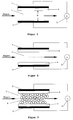
- FIG. 1 shows the basic structure of such a discharge.
- (2) and (3) denote the two metallic electrodes, facing each other and with an AC voltage source (5) are connected.
- Electrode (2) covered with a dielectric (4).
- Such Discharge is referred to as being dielectrically impeded on one side.
- the desired result Discharge.
- the voltage required depends on the free distance d between dielectric and counter electrode as well as from Pressure in the discharge path.
- the distance d is preferred between 0.5 and 10 mm.
- the necessities Voltages are then between 5 and 15 kV.
- the frequency the AC voltage can be between 50 Hz and 250 kHz to get voted.
- FIG. 2 shows a modification of the arrangement of Figure 1.
- both electrodes are covered with a dielectric.
- the gas discharge that forms in the discharge space is therefore referred to as dielectrically impeded on both sides.
- the discharge space can be filled (6) be filled, but none towards the exhaust gas flow may exert great flow resistance.
- the filling of the Discharge path has the consequence that the discharge essentially runs over the surface of the packing. Thereby higher power can be coupled into the discharge become what leads to improved sales of the Nitrogen oxides leads to nitrogen dioxide and nitric acid.
- At the packing or pellets can be spherical Aggiomerate or cylindrical or ring-shaped Trade extrudates. In principle, all are from the Technique of fixed bed catalysts known forms of Suitable pellets. Preference is given to those forms which geometrical surface as high as possible lowest possible flow resistance for the exhaust gas exhibit.
- the electrodes can be aligned parallel to each other two-dimensional structures or a coaxial arrangement with a center electrode by a tubular electrode is surrounded, form.
- Discharge filaments can provide spatial inhomogeneities be that to local field surges and thus to training discharge.
- Figures 4 to 6 show different arrangements of the Discharge line (hereinafter also referred to as a plasma reactor) in the exhaust gas cleaning system of the internal combustion engine.
- the plasma reactor is in front of the Nitrogen oxide storage arranged. That in the plasma reactor below nitrogen dioxide and the lean exhaust gas conditions Nitric acid is passed through the nitrogen oxide storage and react with its storage material to nitrates (Storage phase).
- the memory If the memory has reached its storage capacity, it must he will be regenerated. This is done by lowering the Air number ⁇ of the exhaust gas to values below 1. As a result the stored nitrates decompose and leave the Nitrogen oxide storage (desorption phase).
- the Nitrogen oxides with the reductive components of the greased Exhaust gas is a catalytic converter behind the nitrogen oxide storage built into the exhaust system.
- the barrier discharge can also occur during the desorption phase keep running. However, there is a possibility that Interrupt barrier discharge during this phase because the entire exhaust gas purification from the downstream exhaust gas catalytic converter is taken over.
- the arrangement shown in FIG. 4 can be modified in this regard be that the nitrogen oxide storage material itself with at least one metal from the platinum group or from the first row of transition metals (elements with the Atomic numbers 21 to 30) of the periodic system of the elements is equipped as catalytically active components.
- the nitrogen oxide storage material also has a catalytic one Skills on. Supported during the storage phase it does the function of the plasma reactor through oxidation of nitric oxide, which the plasma reactor under Circumstances left unchanged to nitrogen dioxide and storage as nitrate. During the desorption phase it can implement the desorbed nitrogen oxides with the catalyze reductive components of the exhaust gas, so that ever after dimensioning the exhaust system, if necessary, to the downstream exhaust catalytic converter in Figure 4 omitted can be.
- the nitrogen oxide storage material can also Discharge space of the plasma reactor can be accommodated. Thereby it is possible, as in the case of the inert packing, to couple a higher energy density into the discharge.
- the nitrogen dioxide formed in the gas discharge and the Nitric acid are formed on the storage catalyst immediately after formation converted into nitrates and stored.
- the Nitrogen oxide storage material is again an exhaust gas catalytic converter for the implementation of nitrogen oxides during the desorption phase downstream.
- the storage material with catalytically active Components from the platinum group and from the first row the transition metals of the periodic system of the elements be provided, on the one hand, the effect of the plasma during support the storage phase and on the other hand during reduce the released nitrogen oxides during the desorption phase.
- the nitrogen oxide storage catalytic converter as a combination of a conventional catalytic converter to train with the storage components. Due to the plasma support, the loading of the storage catalytic converter can with the catalytically active precious metals be reduced.
- the plasma reactor a starting catalyst and / or a hydrocarbon adsorber are prefixed (see Figure 6). This will positively influences the light-off behavior of exhaust gas cleaning and hydrocarbon emissions during the cold start phase suppressed.
- the storage catalyst is in the form of pellets in the Filled discharge space, so is a large part of the storage material inside the pellets for the nitrogen oxide components it is difficult to access and is underused.
- An improvement in this situation can be achieved if the storage material is on the inner walls of the flow channels an inert support body in honeycomb form as a coating is applied.
- FIG. 7 shows such an arrangement.
- the honeycomb body 11 is installed in a converter housing 10.
- Exhaust gas catalysts flow the exhaust gas through the flow channels of the honeycomb body.
- the electrical gas discharge is also passed through the flow channels.
- the end faces of the honeycomb body are included perforated, dielectric coated discharge electrodes (12). (13) denotes the dielectric Coating.
- One way to put such electrodes on the For example, applying end faces consists of: Front surfaces by sputtering with suitable To occupy layers.
- FIG. 8 shows a cross section through the honeycomb body perpendicular to the flow channels 23 for the exhaust gas.
- the Honeycomb alternately consists of layers of smooth (21) and corrugated (20) metal foils, which are coated on both sides with the Nitrogen oxide storage material (22) are coated.
- the smooth ones Foils are on a common electrical wire with one pole of the high voltage source (5) and the corrugated Foils connected to the second pole of the voltage source.
- An electrical discharge occurs when a voltage is applied in each flow channel 23 transverse to the flow of the exhaust gas instead.
- the coating of the metal foils with the nitrogen oxide storage material acts as a dielectric and simultaneously takes over the electrical insulation of two neighboring metal foils.
- the discharge voltage can be chosen to be correspondingly low become.
- the length of the honeycomb body not restricted as in the embodiment according to FIG. 7.
- corrugated and smooth metal foils are together combined and form a stack of films.
- it can also two differently corrugated metal foils with each other be combined.
- the type of curl, as well the cross-sectional dimensions of the flow channels can Application requirements are adjusted.
- the coating from the storage material on the metal foils is unable to function as a dielectric barrier, it is possible to a dielectric interlayer between the carrier and bring the storage layer. Alternatively, you can even the smooth metal foil through a dielectric acting barrier, for example in the form of a ceramic Foil to be replaced.
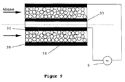
- Figure 9 shows a coaxial plasma reactor.
- the Inner surface of the inner tube and the outer surface of the outer tube are covered with metallic electrodes (33) and (32).
- the outer and inner tubes consisted of 2 mm thick Quartz glass.
- the outer tube had an outer diameter of 4 and the inner tube has an inner diameter of 2.6 cm.
- the Length of the reactor was 20 and the length of the electrodes 16 cm.
- the discharge was operated at a frequency of 1 kHz. The measurements were carried out at room temperature.
- the absorption of the gas mixture was in the range between 200 and 400 nm measured with a UV-VIS spectrometer.
- Figure 10a shows the spectrum of the untreated gas mixture as it was fed into the reactor. This spectrum shows the characteristic absorption bands and lines of NO, HNO 3 and NO 2 . The presence of NO can be seen from the three sharp absorption lines below 230 nm. Superimposed on these absorption lines is a broad absorption band between 200 and about 250 nm, which can be assigned to nitric acid. Above 300 nm, another very broad absorption band can be seen, which is caused by NO 2 .
- FIG. 10b shows the spectrum of the gas mixture after passing through the reactor filled with aluminum oxide pellets without the gas discharge being switched on.
- the pellets contained barium oxide in a concentration of 5% by weight, based on the total weight of the pellets.
- the diameters of the pellets were in the range between 1.5 and 2 mm.
- the spectrum of Figure 10b shows that the pellets doped with barium oxide absorb both NO 2 and HNO 3 quantitatively.
- FIG. 10c shows the absorption spectrum of the gas mixture behind the reactor when the gas discharge is switched on. Within the scope of the measurement accuracy, no more oxidized nitrogen species can be seen. The nitrogen oxide contained in the synthesis gas mixture was thus oxidized to NO 2 by the gas discharge and immediately absorbed by the pellets doped with barium oxide.
Landscapes
- Engineering & Computer Science (AREA)
- Chemical & Material Sciences (AREA)
- Combustion & Propulsion (AREA)
- Chemical Kinetics & Catalysis (AREA)
- Oil, Petroleum & Natural Gas (AREA)
- Health & Medical Sciences (AREA)
- General Engineering & Computer Science (AREA)
- Analytical Chemistry (AREA)
- General Chemical & Material Sciences (AREA)
- Mechanical Engineering (AREA)
- Biomedical Technology (AREA)
- Environmental & Geological Engineering (AREA)
- Toxicology (AREA)
- Exhaust Gas After Treatment (AREA)
- Exhaust Gas Treatment By Means Of Catalyst (AREA)
- Catalysts (AREA)
- Treating Waste Gases (AREA)
Abstract
Description
- Figur 1:
- Dielektrische Barriereentladung mit parallelen, flächigen Elektroden; einseitig dielektrisch behinderte Entladung
- Figur 2:
- Dielektrische Barriereentladung mit parallelen, flächigen Elektroden; beidseitig dielektrisch behinderte Entladung
- Figur 3:
- Dielektrische Barriereentladung mit parallelen, flächigen Elektroden; beidseitig dielektrisch behindert; mit Pellets gefüllter Entladungsraum
- Figur 4-6:
- Verschiedene Anordnung des Plasmareaktors im Abgasreinigungssystem des Verbrennungsmotors
- Figur 7:
- Plasmareaktor in Form eines Wabenkörpers in einem Konvertergehäuse mit axial geführter Entladung
- Figur 8:
- Plasmareaktor in Form eines metallischen Wabenkörpers mit transversal geführter Entladung
- Figur 9:
- Koaxialer Reaktor mit Pelletfüllung
- Figur 10:
- Absorptionsspektren einer unbhandelten Synthesegasmischung (Figur 10a), einer über Bariumoxidpellets geleiteten Synthesegasmischung (Figur 10b) und einer Synthesegasmischung nach Leiten über Bariumoxidpellets bei gleichzeitig eingeschalteter Gasentladung
| Zusammensetzung der Synthesegasmischung | ||
| Stoff | Volumenstrom [Nl] | Konzentration [Vol.-%] bei T = 293 K |
| N2 | 1,0 | 78 |
| O2 | 0,2 | 19 |
| H2O | 26,0·10-3 | 2,6 |
| NO | 1,2·10-3 | 1000 Vol.-ppm |
| Summe | 1,2 | 100 |
Claims (15)
- Verfahren zur Verminderung des Stickoxidgehaltes der Abgase eines Verbrennungsmotors durch Speichern der Stickoxide an einem Stickoxidspeichermaterial während Betriebsphasen des Motors mit überstöchiometrischem Luft/Kraftstoffverhältnis in Form von Nitraten (Speicherphase), Zersetzen der Nitrate zu Stickoxiden während kurzzeitiger Betriebshasen mit unterstöchiometrischem Luft/Kraftstoffverhältnis (Desorptionsphase) und Reduktion der freigesetzten Stickoxide,
dadurch gekennzeichnet,
daß die Abgase zumindest während der Speicherphase in einer elektrischen Gasentladung behandelt und das gebildete Stickstoffdioxid und die gebildete Salpetersäure am Stickoxidspeichermaterial gespeichert werden. - Verfahren nach Anspruch 1,
dadurch gekennzeichnet,
daß die Abgase nach der Behandlung in der Gasentladung über das Stickoxidspeichermaterial und anschließend über einen Abgaskatalysator geführt werden. - Verfahren nach Anspruch 2,
dadurch gekennzeichnet,
daß sich in der Gasentladung inerte Füllkörper befinden. - Verfahren nach Anspruch 1,
dadurch gekennzeichnet,
daß die Abgase nach der Behandlung in der Gasentladung über das Stickoxidspeichermaterial geführt werden, welches zusätzlich als katalytisch aktive Komponenten wenigstens ein Metall aus der Platingruppe oder der ersten Reihe der Übergangsmetalle des periodischen Systems der Elemente enthält. - Verfahren nach Anspruch 4,
dadurch gekennzeichnet,
daß sich in der Gasentladung inerte Füllkörper befinden. - Verfahren nach Anspruch 1,
dadurch gekennzeichnet,
daß das Stickoxidspeichermaterial in der Gasentladung angeordnet ist. - Verfahren nach Anspruch 6,
dadurch gekennzeichnet,
daß die Abgase nach Verlassen der Gasentladung über einen Abgaskatalysator geführt werden. - Verfahren nach Anspruch 6,
dadurch gekennzeichnet,
daß das Stickoxidspeichermaterial zusätzlich als katalytisch aktive Komponenten wenigstens ein Metall aus der Platingruppe oder der ersten Reihe der Übergangsmetalle des periodischen Systems der Elemente enthält. - Verfahren nach Anspruch 6,
dadurch gekennzeichnet,
daß das Stickoxidspeichermaterial in Form einer Pelletschüttung in der elektrischen Gasentladung angeordnet ist. - Verfahren nach Anspruch 6,
dadurch gekennzeichnet,
daß das Stickoxidepeichermaterial in Form einer Beschichtung auf den Wänden der Strömungskanäle eines Wabenkörpers aufgebracht ist und die Gasentladung durch die Strömungskanäle hindurchgeführt wird. - Verfahren nach Anspruch 6,
dadurch gekennzeichnet,
daß das Stickoxidspeichermaterial in Form einer Beschichtung auf den Wänden der Strömungskanäle eines Wabenkörpers aufgebracht ist und die Gasentladung transversal zur Strömung des Abgases betrieben wird. - Verfahren nach Anspruch 11,
dadurch gekennzeichnet,
daß zwischen den Wänden des Wabenkörpers und dem Stickoxidspeichermaterial eine dielektrische Zwischenschicht angeordnet ist. - Verfahren nach einem der vorstehenden Ansprüche,
dadurch gekennzeichnet,
daß die Gasentladung kontinuierlich während der Speicher- und Desorptionsphase betrieben wird. - Verfahren nach Anspruch 13,
dadurch gekennzeichnet,
daß es sich bei der Gasentladung um eine dielektrische Barriere-Entladung handelt, welche mit einer Frequenz zwischen 50 Hz und 250 kHz betrieben wird. - Verfahren nach Anspruch 13,
dadurch gekennzeichnet,
daß dem Stickoxidspeichermaterial ein Startkatalysator und/oder ein Kohlenwasserstoffadsorber vorgeschaltet ist.
Applications Claiming Priority (2)
| Application Number | Priority Date | Filing Date | Title |
|---|---|---|---|
| DE19819372A DE19819372C2 (de) | 1998-04-30 | 1998-04-30 | Verfahren zur Verminderung des Stickoxidgehaltes der Abgase eines Verbrennungsmotors |
| DE19819372 | 1998-04-30 |
Publications (3)
| Publication Number | Publication Date |
|---|---|
| EP0953375A2 true EP0953375A2 (de) | 1999-11-03 |
| EP0953375A3 EP0953375A3 (de) | 2000-03-08 |
| EP0953375B1 EP0953375B1 (de) | 2005-09-21 |
Family
ID=7866313
Family Applications (1)
| Application Number | Title | Priority Date | Filing Date |
|---|---|---|---|
| EP99108398A Expired - Lifetime EP0953375B1 (de) | 1998-04-30 | 1999-04-29 | Verfahren zur Verminderung des Stickoxidgehaltes der Abgase eines Verbrennungsmotors |
Country Status (4)
| Country | Link |
|---|---|
| US (1) | US6238525B1 (de) |
| EP (1) | EP0953375B1 (de) |
| JP (1) | JP4112740B2 (de) |
| DE (2) | DE19819372C2 (de) |
Cited By (4)
| Publication number | Priority date | Publication date | Assignee | Title |
|---|---|---|---|---|
| WO2001083087A1 (de) * | 2000-05-04 | 2001-11-08 | Siemens Aktiengesellschaft | Verfahren und vorrichtung zur abgasreinigung |
| EP1216746A3 (de) * | 2000-12-21 | 2002-07-24 | Delphi Technologies, Inc. | NOx-Adsorber mit SOx-Vergiftungsverhinderung |
| EP1151183A4 (de) * | 1999-01-21 | 2004-08-11 | Litex Inc | Kombinierte plasmareaktor-katalysatorsysteme zur effizienten abgaskontrolle bei verschiedenen arbeitsbedingungen |
| EP2075423A1 (de) * | 2007-12-28 | 2009-07-01 | Kabushiki Kaisha Toyota Jidoshokki | Abgasbehandlungssystem für einen Verbrennungsmotor |
Families Citing this family (17)
| Publication number | Priority date | Publication date | Assignee | Title |
|---|---|---|---|---|
| DK1017477T3 (da) * | 1997-09-09 | 2001-08-06 | Aea Technology Plc | Behandling af afgasser |
| US6423190B2 (en) * | 2000-01-07 | 2002-07-23 | Delphi Technologies, Inc. | Pulse density modulation for uniform barrier discharge in a nonthermal plasma reactor |
| DE10021071C1 (de) * | 2000-04-29 | 2002-03-07 | Omg Ag & Co Kg | Verfahren zur Entfernung von Stickoxiden aus einem Sauerstoff enthaltenden Rauchgasstrom |
| US6774335B2 (en) * | 2000-05-12 | 2004-08-10 | Hokushin Corporation | Plasma reactor and gas modification method |
| DE10027409C1 (de) * | 2000-06-02 | 2001-06-13 | Emitec Emissionstechnologie | Kompakter Plasmareaktor |
| JP4767400B2 (ja) * | 2000-10-25 | 2011-09-07 | 株式会社西部技研 | 揮発性有機物蒸気処理素子 |
| KR20030075472A (ko) | 2002-03-19 | 2003-09-26 | 현대자동차주식회사 | 플라즈마 반응기 및 그 제조방법과 플라즈마 반응기가채용된 차량의 배기가스 저감장치 |
| JP2004346772A (ja) * | 2003-05-20 | 2004-12-09 | Toyota Motor Corp | 排気浄化装置及び方法 |
| US20060185720A1 (en) * | 2005-02-22 | 2006-08-24 | Pentam, Inc. | Method of recycling a nuclear-cored battery |
| US20060186378A1 (en) * | 2005-02-22 | 2006-08-24 | Pentam, Inc. | Crystalline of a nuclear-cored battery |
| US20060185722A1 (en) * | 2005-02-22 | 2006-08-24 | Pentam, Inc. | Method of pre-selecting the life of a nuclear-cored product |
| US20060185975A1 (en) * | 2005-02-22 | 2006-08-24 | Pentam, Inc. | Decomposition unit |
| JP2007307514A (ja) * | 2006-05-22 | 2007-11-29 | Sharp Corp | 気体浄化装置 |
| JP4564546B2 (ja) * | 2008-03-28 | 2010-10-20 | 三井造船株式会社 | ディーゼル排気ガス中の粒子状物質除去装置 |
| JP5222616B2 (ja) * | 2008-04-23 | 2013-06-26 | 日野自動車株式会社 | 排気浄化装置 |
| JP5340629B2 (ja) * | 2008-04-23 | 2013-11-13 | 日野自動車株式会社 | 排気浄化装置 |
| KR20230108638A (ko) * | 2022-01-11 | 2023-07-18 | 삼성전자주식회사 | 공기 정화 장치 및 공기 정화 방법 |
Family Cites Families (16)
| Publication number | Priority date | Publication date | Assignee | Title |
|---|---|---|---|---|
| US3983021A (en) * | 1971-06-09 | 1976-09-28 | Monsanto Company | Nitrogen oxide decomposition process |
| DE3912915C1 (de) * | 1989-04-20 | 1990-12-13 | Degussa Ag, 6000 Frankfurt, De | |
| JP3311012B2 (ja) * | 1992-03-23 | 2002-08-05 | 株式会社豊田中央研究所 | 排気ガス浄化用触媒および排気ガス浄化方法 |
| JPH06269635A (ja) * | 1993-03-19 | 1994-09-27 | Mitsubishi Heavy Ind Ltd | 排ガス処理装置 |
| EP0659465B1 (de) | 1993-12-23 | 1999-04-07 | Fraunhofer-Gesellschaft Zur Förderung Der Angewandten Forschung E.V. | Verfahren und Vorrichtung zur Abgasreinigung |
| DE19510804A1 (de) * | 1995-03-24 | 1996-09-26 | Dornier Gmbh | Verfahren und Vorrichtung zur Stickoxidminderung in Abgasen von Verbrennungsmaschinen |
| DE19513250C2 (de) * | 1995-04-07 | 1999-06-10 | Dornier Gmbh | Verfahren und Vorrichtung zur kontinuierlichen Entfernung von Stickoxiden in Abgasen von Verbrennungsmaschinen |
| DE19518970C1 (de) * | 1995-05-23 | 1996-11-21 | Fraunhofer Ges Forschung | Verfahren und Vorrichtung zur Behandlung von Abgas |
| WO1997003746A1 (de) * | 1995-07-14 | 1997-02-06 | Siemens Aktiengesellschaft | Verfahren und vorrichtung zur plasmachemischen zersetzung und/oder vernichtung von schadstoffen |
| US5746984A (en) * | 1996-06-28 | 1998-05-05 | Low Emissions Technologies Research And Development Partnership | Exhaust system with emissions storage device and plasma reactor |
| US5914015A (en) | 1996-07-15 | 1999-06-22 | Battelle Memorial Institute | Method and apparatus for processing exhaust gas with corona discharge |
| US5711147A (en) * | 1996-08-19 | 1998-01-27 | The Regents Of The University Of California | Plasma-assisted catalytic reduction system |
| US6038853A (en) * | 1996-08-19 | 2000-03-21 | The Regents Of The University Of California | Plasma-assisted catalytic storage reduction system |
| US6038854A (en) * | 1996-08-19 | 2000-03-21 | The Regents Of The University Of California | Plasma regenerated particulate trap and NOx reduction system |
| DE19653958A1 (de) * | 1996-12-21 | 1998-06-25 | Degussa | Verfahren zur Verminderung der Stickoxide im Abgas von Verbrennungsmotoren |
| DE19826831A1 (de) * | 1998-04-09 | 1999-10-14 | Fev Motorentech Gmbh | Verfahren zur Verminderung der Schadstoffemission von Kraftfahrzeugen |
-
1998
- 1998-04-30 DE DE19819372A patent/DE19819372C2/de not_active Expired - Fee Related
-
1999
- 1999-04-27 US US09/299,630 patent/US6238525B1/en not_active Expired - Fee Related
- 1999-04-29 DE DE59912566T patent/DE59912566D1/de not_active Expired - Fee Related
- 1999-04-29 EP EP99108398A patent/EP0953375B1/de not_active Expired - Lifetime
- 1999-04-30 JP JP12487599A patent/JP4112740B2/ja not_active Expired - Fee Related
Cited By (5)
| Publication number | Priority date | Publication date | Assignee | Title |
|---|---|---|---|---|
| EP1151183A4 (de) * | 1999-01-21 | 2004-08-11 | Litex Inc | Kombinierte plasmareaktor-katalysatorsysteme zur effizienten abgaskontrolle bei verschiedenen arbeitsbedingungen |
| WO2001083087A1 (de) * | 2000-05-04 | 2001-11-08 | Siemens Aktiengesellschaft | Verfahren und vorrichtung zur abgasreinigung |
| EP1216746A3 (de) * | 2000-12-21 | 2002-07-24 | Delphi Technologies, Inc. | NOx-Adsorber mit SOx-Vergiftungsverhinderung |
| US6887438B2 (en) | 2000-12-21 | 2005-05-03 | Delphi Technologies, Inc. | NOx control |
| EP2075423A1 (de) * | 2007-12-28 | 2009-07-01 | Kabushiki Kaisha Toyota Jidoshokki | Abgasbehandlungssystem für einen Verbrennungsmotor |
Also Published As
| Publication number | Publication date |
|---|---|
| US6238525B1 (en) | 2001-05-29 |
| DE19819372A1 (de) | 1999-11-04 |
| JPH11347356A (ja) | 1999-12-21 |
| EP0953375B1 (de) | 2005-09-21 |
| DE59912566D1 (de) | 2006-02-02 |
| JP4112740B2 (ja) | 2008-07-02 |
| DE19819372C2 (de) | 2000-03-02 |
| EP0953375A3 (de) | 2000-03-08 |
Similar Documents
| Publication | Publication Date | Title |
|---|---|---|
| EP0953375B1 (de) | Verfahren zur Verminderung des Stickoxidgehaltes der Abgase eines Verbrennungsmotors | |
| EP1023935B1 (de) | Verfahren zur selektiven katalytischen Reduktion von Stickoxiden in sauerstoffhaltigen Abgasen | |
| DE112004002324B4 (de) | Verfahren zum Reduzieren von NOx in Dieselmotorenabgas | |
| DE3877229T2 (de) | Verfahren zum entfernen von nox aus fluidstroemen. | |
| EP0979135B1 (de) | Vorrichtung und verfahren zur zersetzung von schadstoffen in abgasen von verbrennungsprozessen | |
| EP2428659B1 (de) | Katalysator zur Entfernung von Stickoxiden aus dem Abgas von Dieselmotoren | |
| DE112014004694B4 (de) | Abgassystem mit einem darin angeordneten Katalysator | |
| DE60111040T2 (de) | Plasmaunterstützte gasbehandlung | |
| DE2907106C2 (de) | Abgaskatalysator und seine Verwendung zur Reinigung der Abgase von Verbrennungskraftmaschinen | |
| DE69800838T2 (de) | Behandlung von abgasen | |
| DE60109300T2 (de) | Verfahren und vorrichtung zur entfernung von stickoxiden im abgas einer brennkraftmaschine | |
| DE60011282T2 (de) | Verfahren für abgasplasmabehandlung | |
| DE19923781C2 (de) | Verfahren und Vorrichtung zur Entfernung von Ruß aus dem Abgas eines Dieselmotors | |
| EP1095907A2 (de) | Verfahren zur plasmakatalytischen Erzeugung von Ammoniak | |
| EP1961933A1 (de) | Katalytisch aktiviertes Dieselpartikelfilter mit Ammoniak-Sperrwirkung | |
| US6887438B2 (en) | NOx control | |
| DE102009014458A1 (de) | Abgas-Reinigungsvorrichtung | |
| DE10021071C1 (de) | Verfahren zur Entfernung von Stickoxiden aus einem Sauerstoff enthaltenden Rauchgasstrom | |
| DE19826831A1 (de) | Verfahren zur Verminderung der Schadstoffemission von Kraftfahrzeugen | |
| EP0659465B1 (de) | Verfahren und Vorrichtung zur Abgasreinigung | |
| DE19808098C1 (de) | Verfahren und Vorrichtung zur Abgasreinigung | |
| DE4423397C2 (de) | Verfahren und Vorrichtung zur Abgasreinigung | |
| DE60223186T2 (de) | Behandlungssystem für Abgas und dessen Verwendung | |
| EP0811418B1 (de) | Abgaskatalysator | |
| WO2020089264A1 (de) | Katalysator zur verwendung bei einer selektiven nox-reduktion in nox-haltigen abgasen, verfahren zur herstellung eines katalysators, vorrichtung zur selektiven nox-reduktion und verfahren zur selektiven nox-reduktion |
Legal Events
| Date | Code | Title | Description |
|---|---|---|---|
| PUAI | Public reference made under article 153(3) epc to a published international application that has entered the european phase |
Free format text: ORIGINAL CODE: 0009012 |
|
| AK | Designated contracting states |
Kind code of ref document: A2 Designated state(s): DE FR GB |
|
| AX | Request for extension of the european patent |
Free format text: AL;LT;LV;MK;RO;SI |
|
| PUAL | Search report despatched |
Free format text: ORIGINAL CODE: 0009013 |
|
| AK | Designated contracting states |
Kind code of ref document: A3 Designated state(s): AT BE CH CY DE DK ES FI FR GB GR IE IT LI LU MC NL PT SE |
|
| AX | Request for extension of the european patent |
Free format text: AL;LT;LV;MK;RO;SI |
|
| 17P | Request for examination filed |
Effective date: 20000201 |
|
| AKX | Designation fees paid |
Free format text: DE FR GB |
|
| RAP1 | Party data changed (applicant data changed or rights of an application transferred) |
Owner name: DMC2 DEGUSSA METALS CATALYSTS CERDEC AG |
|
| RAP1 | Party data changed (applicant data changed or rights of an application transferred) |
Owner name: OMG AG & CO. KG |
|
| RAP1 | Party data changed (applicant data changed or rights of an application transferred) |
Owner name: UMICORE AG & CO. KG |
|
| GRAP | Despatch of communication of intention to grant a patent |
Free format text: ORIGINAL CODE: EPIDOSNIGR1 |
|
| GRAS | Grant fee paid |
Free format text: ORIGINAL CODE: EPIDOSNIGR3 |
|
| GRAA | (expected) grant |
Free format text: ORIGINAL CODE: 0009210 |
|
| AK | Designated contracting states |
Kind code of ref document: B1 Designated state(s): DE FR GB |
|
| REG | Reference to a national code |
Ref country code: GB Ref legal event code: FG4D Free format text: NOT ENGLISH |
|
| REF | Corresponds to: |
Ref document number: 59912566 Country of ref document: DE Date of ref document: 20051027 Kind code of ref document: P |
|
| GBT | Gb: translation of ep patent filed (gb section 77(6)(a)/1977) |
Effective date: 20051114 |
|
| REF | Corresponds to: |
Ref document number: 59912566 Country of ref document: DE Date of ref document: 20060202 Kind code of ref document: P |
|
| ET | Fr: translation filed | ||
| PLBE | No opposition filed within time limit |
Free format text: ORIGINAL CODE: 0009261 |
|
| STAA | Information on the status of an ep patent application or granted ep patent |
Free format text: STATUS: NO OPPOSITION FILED WITHIN TIME LIMIT |
|
| 26N | No opposition filed |
Effective date: 20060622 |
|
| PGFP | Annual fee paid to national office [announced via postgrant information from national office to epo] |
Ref country code: FR Payment date: 20090414 Year of fee payment: 11 Ref country code: DE Payment date: 20090422 Year of fee payment: 11 |
|
| PGFP | Annual fee paid to national office [announced via postgrant information from national office to epo] |
Ref country code: GB Payment date: 20090421 Year of fee payment: 11 |
|
| GBPC | Gb: european patent ceased through non-payment of renewal fee |
Effective date: 20100429 |
|
| REG | Reference to a national code |
Ref country code: FR Ref legal event code: ST Effective date: 20101230 |
|
| PG25 | Lapsed in a contracting state [announced via postgrant information from national office to epo] |
Ref country code: DE Free format text: LAPSE BECAUSE OF NON-PAYMENT OF DUE FEES Effective date: 20101103 |
|
| PG25 | Lapsed in a contracting state [announced via postgrant information from national office to epo] |
Ref country code: GB Free format text: LAPSE BECAUSE OF NON-PAYMENT OF DUE FEES Effective date: 20100429 |
|
| PG25 | Lapsed in a contracting state [announced via postgrant information from national office to epo] |
Ref country code: FR Free format text: LAPSE BECAUSE OF NON-PAYMENT OF DUE FEES Effective date: 20100430 |