EP0952391B1 - Verfahren und Vorrichtung zur vollständigen Verbrennung stückiger, aschehaltiger Brennstoffe - Google Patents
Verfahren und Vorrichtung zur vollständigen Verbrennung stückiger, aschehaltiger Brennstoffe Download PDFInfo
- Publication number
- EP0952391B1 EP0952391B1 EP99107651A EP99107651A EP0952391B1 EP 0952391 B1 EP0952391 B1 EP 0952391B1 EP 99107651 A EP99107651 A EP 99107651A EP 99107651 A EP99107651 A EP 99107651A EP 0952391 B1 EP0952391 B1 EP 0952391B1
- Authority
- EP
- European Patent Office
- Prior art keywords
- fuel
- combustion
- pieces
- cone
- ash
- Prior art date
- Legal status (The legal status is an assumption and is not a legal conclusion. Google has not performed a legal analysis and makes no representation as to the accuracy of the status listed.)
- Expired - Lifetime
Links
Images

Classifications
-
- F—MECHANICAL ENGINEERING; LIGHTING; HEATING; WEAPONS; BLASTING
- F23—COMBUSTION APPARATUS; COMBUSTION PROCESSES
- F23B—METHODS OR APPARATUS FOR COMBUSTION USING ONLY SOLID FUEL
- F23B5/00—Combustion apparatus with arrangements for burning uncombusted material from primary combustion
- F23B5/02—Combustion apparatus with arrangements for burning uncombusted material from primary combustion in main combustion chamber
-
- F—MECHANICAL ENGINEERING; LIGHTING; HEATING; WEAPONS; BLASTING
- F23—COMBUSTION APPARATUS; COMBUSTION PROCESSES
- F23G—CREMATION FURNACES; CONSUMING WASTE PRODUCTS BY COMBUSTION
- F23G2202/00—Combustion
- F23G2202/10—Combustion in two or more stages
- F23G2202/106—Combustion in two or more stages with recirculation of unburned solid or gaseous matter into combustion chamber
-
- F—MECHANICAL ENGINEERING; LIGHTING; HEATING; WEAPONS; BLASTING
- F23—COMBUSTION APPARATUS; COMBUSTION PROCESSES
- F23G—CREMATION FURNACES; CONSUMING WASTE PRODUCTS BY COMBUSTION
- F23G2203/00—Furnace arrangements
- F23G2203/101—Furnace arrangements with stepped or inclined grate
-
- F—MECHANICAL ENGINEERING; LIGHTING; HEATING; WEAPONS; BLASTING
- F23—COMBUSTION APPARATUS; COMBUSTION PROCESSES
- F23G—CREMATION FURNACES; CONSUMING WASTE PRODUCTS BY COMBUSTION
- F23G2203/00—Furnace arrangements
- F23G2203/20—Rotary drum furnace
-
- F—MECHANICAL ENGINEERING; LIGHTING; HEATING; WEAPONS; BLASTING
- F23—COMBUSTION APPARATUS; COMBUSTION PROCESSES
- F23G—CREMATION FURNACES; CONSUMING WASTE PRODUCTS BY COMBUSTION
- F23G2209/00—Specific waste
- F23G2209/26—Biowaste
- F23G2209/261—Woodwaste
Definitions
- the invention relates to a method for complete Burning lumpy, ashy fuels, especially of such different piece sizes in a combustion device, of the fuel pieces at a first end be abandoned and in which they burn during Towards a second end, as well as one Device with which such a method can be carried out.
- US-1 980 928 shows a device for blurring Coal and other carbonaceous material consisting of a slightly inclined rotary tube into which the one to be smoldered Fuel is abandoned at the higher end and through that it travels under the force of gravity and rotation of the pipe, whereby he is becoming more and more cuddly.
- Free-moving steel balls are used for shattering of the fuel pieces. These steel balls can do their job on unburned pieces but not with certainty, because these are often tough, which is especially true for wood.
- ER-24 46 312 describes a method and an apparatus for the recovery of soot, combustible mineral oils, fuel gas and steel from used vehicle tires by pyrolysis.
- the Tires are cut into small pieces, then the Steel reinforcement mechanically separated from the rubber parts that then be fed to pyrolysis.
- the Rubber parts into a carbon-containing solid phase and a hydrocarbon-containing one Vapor phase separated. The one with a burn Problems associated with ashes are this procedure strange.
- From US-4,657,561 is a method for recovering Known fuel from coal ash, the unburned carbon contains in particle form and from the exhaust gases of a coal dust burner, a fluidized bed oven or a coke oven was separated. To do this, the ash with water, a binder and a surface activator and coarse Particles of high carbon content agglomerate. Fine particles with a high ash content are separated from the coarse particles, so that the coarse particles can now be dehydrated. The Coarse particles can then enter the combustion process that supplies the fly ash be fed again. With the control of the This document does not deal with the combustion process.
- DE 195 28 765 A1 describes a discharge device for a Smoldering drum known for waste where at the exit of the smoldering drum a rotating discharge tube for the passage of the Fuel together with vaults and the carbonization gas is provided.
- This spill is caused by materials in the fuel are included and for example metal packaging tapes, Wires, springs, e.g. come from upholstery or mattresses, Bowden cables and the like. If these materials are the Smoldering drum run through, form from fibrous Metal strips and metal threads, which in practice have lengths of 1 can reach up to 5 meters and diameter up to 40 cm and as Vaults are called.
- Such vaults hinder fuel transportation through the smoldering drum.
- a device for Separate the vault from the rest of the residue This The separating device can be a rotating rod screen.
- EP 0 086 488 A2 discloses a discharge device for a Rotary tube furnace for pyrolysis of waste, comprising a bar screen, with which the solid residue in two differently fine fractions is divided.
- the bar screen is one at the outlet end attached to the rotating tube and rotatable with this rod cage.
- Whose rods are held so that their each of the The face of the rotary tube has protruding ends and from the exit plane of the rotary tube to the freely protruding ones Continuous slits ends between adjacent bars are fixed, which begin with the outlet end of the rotary tube.
- the distance between the bars is chosen so that the Smoldering coke between the rods falls through and coarse Solids such as cans, metal parts and stones are retained become. Otherwise, this rotary kiln has all of these properties that were discussed at the beginning and in particular hinder the burnout of coarser pieces of fuel.
- the invention has for its object a method of the beginning mentioned type and suitable devices for its implementation to indicate with which a complete burnout of the Fuel can be achieved.
- the problem underlying the invention is therefore not by extending the combustion zone but by taking measures solved, which allow a drastic shortening of the same. Thereby only the respective fine portion of the lumpy Fuel completely when the combustion zone is first run through burned out. Burn medium sized pieces at one Partial passage, and large pieces may have just ignited.
- the mixture of separated ash has also proven itself and still glowing fine particles together with air from one Have radial fans sucked in and closed via a pipeline to promote an ash silo. Testing showed that the proportion of unburned material still in the ashes below 1% and was therefore at the detection limit.
- the invention can also achieve considerable savings in terms of construction costs, in particular for the combustion device, for example the grate.
- firing grates according to the prior art for example when burning waste wood, may be loaded with a maximum of 0.8 to 1.0 MW / m 2 if the burnout should not be too bad
- the method according to the invention achieves outputs of 3 to 6 MW / m 2 achieved with perfect burnout.
- the upper limit applies to shredded wood, the lower limit if there are large pieces of up to 300 mm edge length.
- Fig. 1 is an entry of fuel to a combustion device shown in the form of a grate, symbolized by 2 is.
- This grate has a discharge 3 for grate diarrhea, especially ashes.
- At the exit end of the Grate 2 is connected to a separator 4, one Ash discharge 5 and a return outlet 6, which too a return device 7 leads to the inlet end of the grate 2 opens.
- FIG. 2 and the top view of FIG. 3 show a device for carrying out the invention Method with the same reference numerals for those based on FIG. 1 described assemblies, so that a detailed explanation can be dispensed with.
- FIGS. 2 and 3 of the grate 2 as a step grate is trained.
- a rotary tube can also be used instead of the grate are used, since this has the same effect in the present case is working.
- a feedback device 7 is in the example shown a screw conveyor is provided, but it should be noted that also a chain conveyor or other suitable conveyor can be used.
- the separation device 4 a sieve in a heat-resistant version, which the not burned coarser fuel pieces of a predetermined minimum size catches and over an overflow 6 of the screw conveyor 7 feeds.
- the latter is heat-resistant and thermally insulated, around the glowing or burning pieces of fuel heat loss as low as possible at the inlet end of the grate 2 supply.
- a separator can also be used known sieve drum can be used.
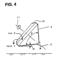
- a separating cone as the separating device 4 in an advantageous manner can be used as shown in Fig. 4.
- a Separating cone is a conical hollow body (hollow cone) 9 which the cone base has an inwardly directed edge 10 and rotates about an inclined axis 11, which is directed so that the tip of the cone points downwards.
- the cone 9 is like this arranged that its lower surface line from the cone tip starting at a small angle ⁇ against the horizontal in Direction towards the base of the cone.
- the cone angle ⁇ is chosen so that the upper surface line of the cone tip to the cone base diagonally or vertically upwards runs.
- the shape shown in the drawing corresponds to about a usable version.
- This hollow cone 9 acts as follows:
- a Rotary tube as a combustion device with an attached rotationally symmetrical Sieve basket as separation device.
- a rotary kiln demands however, a longer length than a grate because it is large Parts run faster through a rotating tube than through a grate, for the large parts, however, a certain minimum dwell time in the actual combustion process is required.
- He can also Combustion fraction in the separating cone at the expense of the combustion fraction be increased on the grate or in the rotary tube, etc.
- Essential is that every piece of fuel is the invention Process goes through, after which it passes through the combustion zone so often is carried out as necessary to make it completely ashes burn, with the ash formed after each pass is separated.
Landscapes
- Engineering & Computer Science (AREA)
- Physics & Mathematics (AREA)
- Chemical & Material Sciences (AREA)
- Combustion & Propulsion (AREA)
- Thermal Sciences (AREA)
- Mechanical Engineering (AREA)
- General Engineering & Computer Science (AREA)
- Gasification And Melting Of Waste (AREA)
- Solid-Fuel Combustion (AREA)
- Combustion Of Fluid Fuel (AREA)
Description
Claims (16)
- Verfahren zum vollständigen Verbrennen von stückigen, aschehaltigen Brennstoffen, insbesondere von solchen unterschiedlicher Stückgrößen, in einer Verbrennungszone, der die Brennstoffstücke an einem ersten Ende aufgegeben werden und in der sie beim Verbrennungsvorgang in Richtung auf ein zweites Ende fortbewegt werden, wobei der Feinanteil des Brennstoffs bei einem Durchgang durch die Verbrennungszone im wesentlichen vollständig verbrannt wird, die gröberen Stücke des Brennstoffs am zweiten Ende der Verbrennungszone aber noch brennen oder gar erst gezündet haben, noch brennender oder glühender Feinanteil falls vorhanden zusammen mit angefallener Asche am zweiten Ende abgetrennt und einem Ausgang zugeführt und dort ausgebrannt wird und die gröberen Brennstoffstücke an das erste Ende der Verbrennungszone zurückgeführt werden.
- Verfahren nach Anspruch 1, dadurch gekennzeichnet, daß der Feinanteil im Austrag mit zusätzlicher Luft in Berührung gebracht wird.
- Verfahren nach Anspruch 1 oder 2, dadurch gekennzeichnet, daß der Feinanteil im Austrag mechanisch bewegt wird.
- Verfahren nach einem der vorhergehenden Ansprüche, dadurch gekennzeichnet, daß der Feinanteil mittels mechanischer Trenneinrichtungen von den größeren Brennstoffstücken abgetrennt wird.
- Verfahren nach einem der Ansprüche 1 bis 4, dadurch gekennzeichnet, daß die Brennstoffstücke während de Rückführung zum ersten Ende der Verbrennungszone mit gesondert zugeführter Luft in Berührung gebracht werden.
- Vorrichtung zum vollständigen Verbrennen von stückigen, aschehaltigen Brennstoffen unterschiedlicher Stückgrößen, enthaltend eine Brenneinrichtung (2) mit einem Träger zum Ablegen des Brennstoffs darauf, Einrichtungen zum Zuführen von Verbrennungsluft, eine Einrichtung zum Zuführen der Brennstoffstücke an einem ersten Ende der Brenneinrichtung (2) und einer Einrichtung zum Bewegen der Brennstoffstücke durch die Brenneinrichtung (2) in Richtung auf ein zweites Ende derselben, weiterhin enthaltend eine Trenneinrichtung (4) am zweiten Ende der Brenneinrichtung (2), die noch brennende oder gar erst gezündete gröbere Brennstoffstücke von vorhandenem Feinanteil des Brennstoffs abtrennt, eine Rückführeinrichtung (7), die die von der Trenneinrichtung (4) abgegebenen gröberen Brennstoffstücke zum ersten Ende der Brenneinrichtung (2) zurückführt, und eine Nachverbrennungseinrichtung (5), die den Feinanteil von der Trenneinrichtung (4) zum vollständigen Ausbrennen desselben entgegennimmt.
- Vorrichtung nach Anspruch 6, dadurch gekennzeichnet, daß die Trenneinrichtung (4) ein Sieb ist.
- Vorrichtung nach Anspruch 6 oder 7, dadurch gekennzeichnet, daß die Brenneinrichtung ein Rost (9) ist.
- Vorrichtung nach einem der Ansprüche 6 und 7, dadurch gekennzeichnet, daß die Brenneinrichtung ein Drehrohr ist.
- Vorrichtung nach einem der Ansprüche 6 bis 9, dadurch gekennzeichnet, daß die Trenneinrichtung ein rotierender Kegel (9) ist, dessen Drehachse (11) von der Kegelspitze her gesehen schräg aufwärts zeigt.
- Vorrichtung nach Anspruch 10, dadurch gekennzeichnet, daß die unterste Mantellinie des Kegels (9) von der Kegelspitze ausgehend leicht abwärts geneigt verläuft.
- Vorrichtung nach einem der Ansprüche 10 und 11, dadurch gekennzeichnet, daß der Kegel (9) einen Öffnungswinkel (β) von etwa 90° hat.
- Vorrichtung nach einem der Ansprüche 10 bis 12, dadurch gekennzeichnet, daß der Rand (10) des Kegels (9) an dessen Basis nach innen gebogen ist.
- Vorrichtung nach einem der Ansprüche 6 bis 13, dadurch gekennzeichnet, daß die Rückführeinrichtung eine Förderschnecke (7) ist.
- Vorrichtung nach einem der Ansprüche 6 bis 13, dadurch gekennzeichnet, daß die Rückführeinrichtung ein Kettenförderer ist.
- Vorrichtung nach einem der Ansprüche 6 bis 15, dadurch gekennzeichnet, daß die Rückführeinrichtung mit Luftzuführungseinrichtungen versehen ist.
Applications Claiming Priority (2)
| Application Number | Priority Date | Filing Date | Title |
|---|---|---|---|
| DE19817119A DE19817119A1 (de) | 1998-04-17 | 1998-04-17 | Verfahren und Vorrichtung zur vollständigen Verbrennung stückiger, aschehaltiger Brennstoffe |
| DE19817119 | 1998-04-17 |
Publications (3)
| Publication Number | Publication Date |
|---|---|
| EP0952391A2 EP0952391A2 (de) | 1999-10-27 |
| EP0952391A3 EP0952391A3 (de) | 2000-03-01 |
| EP0952391B1 true EP0952391B1 (de) | 2003-10-15 |
Family
ID=7864879
Family Applications (1)
| Application Number | Title | Priority Date | Filing Date |
|---|---|---|---|
| EP99107651A Expired - Lifetime EP0952391B1 (de) | 1998-04-17 | 1999-04-16 | Verfahren und Vorrichtung zur vollständigen Verbrennung stückiger, aschehaltiger Brennstoffe |
Country Status (4)
| Country | Link |
|---|---|
| EP (1) | EP0952391B1 (de) |
| AT (1) | ATE252214T1 (de) |
| DE (2) | DE19817119A1 (de) |
| DK (1) | DK0952391T3 (de) |
Families Citing this family (2)
| Publication number | Priority date | Publication date | Assignee | Title |
|---|---|---|---|---|
| DE10213788B4 (de) * | 2002-03-27 | 2007-04-26 | Martin GmbH für Umwelt- und Energietechnik | Verfahren zur Beeinflussung der Eigenschaften von Verbrennungsrückständen aus einer Verbrennungsanlage |
| DE102004050098B4 (de) * | 2004-10-14 | 2007-05-31 | Martin GmbH für Umwelt- und Energietechnik | Verbrennungsanlage, insbesondere Abfallverbrennungsanlage |
Family Cites Families (7)
| Publication number | Priority date | Publication date | Assignee | Title |
|---|---|---|---|---|
| US1980828A (en) * | 1932-01-15 | 1934-11-13 | Harry S Reed | Apparatus and process for distilling and treating coal and other carbonaceous materials |
| FR2446312A2 (fr) * | 1979-01-15 | 1980-08-08 | Intenco Inc | Procede et installation de fabrication de noir de carbone et d'hydrocarbures a partir de pneumatiques uses |
| JPS58109127A (ja) * | 1981-12-22 | 1983-06-29 | Kawasaki Heavy Ind Ltd | 灰処理方法 |
| DE3205366C2 (de) * | 1982-02-16 | 1984-06-07 | Deutsche Kommunal-Anlagen Miete GmbH, 8000 München | Austragsvorrichtung für einen Drehrohrofen |
| JPS5938508A (ja) * | 1982-08-25 | 1984-03-02 | Mitsubishi Heavy Ind Ltd | 固形物燃焼方法 |
| DE19528765C2 (de) * | 1995-08-04 | 1999-03-25 | Siemens Ag | Austragseinrichtung für eine Schweltrommel für Abfall |
| EP0908674A1 (de) * | 1997-10-13 | 1999-04-14 | Asea Brown Boveri AG | Verfahren zur Verbrennung von Müll in einem Verbrennungsofen und zur Aufbereitung der Schlacke aus der Müllverbrennung |
-
1998
- 1998-04-17 DE DE19817119A patent/DE19817119A1/de not_active Withdrawn
-
1999
- 1999-04-16 AT AT99107651T patent/ATE252214T1/de not_active IP Right Cessation
- 1999-04-16 DE DE59907336T patent/DE59907336D1/de not_active Expired - Lifetime
- 1999-04-16 EP EP99107651A patent/EP0952391B1/de not_active Expired - Lifetime
- 1999-04-16 DK DK99107651T patent/DK0952391T3/da active
Also Published As
| Publication number | Publication date |
|---|---|
| ATE252214T1 (de) | 2003-11-15 |
| DK0952391T3 (da) | 2004-02-23 |
| EP0952391A3 (de) | 2000-03-01 |
| DE19817119A1 (de) | 1999-10-21 |
| EP0952391A2 (de) | 1999-10-27 |
| DE59907336D1 (de) | 2003-11-20 |
Similar Documents
| Publication | Publication Date | Title |
|---|---|---|
| DE4217070C5 (de) | Verbrennungsvorrichtung und -verfahren | |
| DE1809874C3 (de) | ||
| DE3811820A1 (de) | Verfahren und anlage zur thermischen abfallentsorgung | |
| EP0764614B1 (de) | Anlage und Verfahren zur Herstellung von Zementklinker | |
| EP0862019B1 (de) | Verfahren und Vorrichtung zur thermischen Behandlung von Flugstäuben aus Rostverbrennungsanlagen | |
| DE3347056A1 (de) | Verfahren zur aufbereitung von haus- und/oder hausmuellaehnlichem gewerbemuell zur herstellung eines brennstoffs, sowie verbrennungsofen | |
| DE4308490C2 (de) | Verfahren und Vorrichtung zur Zerstörung von Schadstoffen | |
| EP0952391B1 (de) | Verfahren und Vorrichtung zur vollständigen Verbrennung stückiger, aschehaltiger Brennstoffe | |
| CH615745A5 (de) | ||
| DE2721237A1 (de) | Verfahren zur verbrennung von stark feuchten, vornehmlich pflanzlichen abfallbrennstoffen und verbrennungsanlage zur durchfuehrung des verfahrens | |
| DE19920143A1 (de) | Verfahren und Anlage zur thermischen Behandlung von mehlförmigen Rohmaterialien | |
| DE4219231C1 (de) | Verfahren zur Verbrennung von Abfall und Abfallverbrennungsanlage | |
| EP0908674A1 (de) | Verfahren zur Verbrennung von Müll in einem Verbrennungsofen und zur Aufbereitung der Schlacke aus der Müllverbrennung | |
| DE3910271A1 (de) | Verfahren zum betreiben einer wirbelbettfeuerung auf kohlenbasis | |
| DE2104485C3 (de) | Müllverbrennungsofen | |
| DE249034C (de) | ||
| DE3039469C2 (de) | Verfahren zur energetischen Nutzung von Gestein mit Kohleeinschlüssen und/oder normaler Förderkohle | |
| DE102008010235A1 (de) | Verfahren zur Wurfbeschickung bei Feuerungsanlagen und Feuerungsanlage | |
| DE1181360B (de) | Verfahren und Anlage zur Muellverbrennung in einem Dampferzeuger | |
| DE19744814C2 (de) | Verfahren und Anlage zur Gewinnung einer C-haltigen Wertstofffraktion | |
| DE4414321A1 (de) | Verfahren und Anlage zur Verwertung von mit organischen Rückständen versetzten Reststoffen sowie Sinter | |
| DE631225C (de) | Verfahren und Einrichtung zur Verbrennung von Muell | |
| DE4022535C1 (de) | ||
| DE19910530A1 (de) | Vorrichtung zum kontinuierlichen Verbrennen von festen Abfallstoffen, Speiseabfällen und Ölschlamm | |
| DE523097C (de) | Verfahren zur Verbrennung von Muell und anderen Abfallstoffen in Schachtoefen |
Legal Events
| Date | Code | Title | Description |
|---|---|---|---|
| PUAI | Public reference made under article 153(3) epc to a published international application that has entered the european phase |
Free format text: ORIGINAL CODE: 0009012 |
|
| AK | Designated contracting states |
Kind code of ref document: A2 Designated state(s): AT BE CH CY DE DK ES FI FR GB GR IE IT LI LU NL PT SE |
|
| AX | Request for extension of the european patent |
Free format text: AL;LT;LV;MK;RO;SI |
|
| PUAL | Search report despatched |
Free format text: ORIGINAL CODE: 0009013 |
|
| AK | Designated contracting states |
Kind code of ref document: A3 Designated state(s): AT BE CH CY DE DK ES FI FR GB GR IE IT LI LU MC NL PT SE |
|
| AX | Request for extension of the european patent |
Free format text: AL;LT;LV;MK;RO;SI |
|
| RIC1 | Information provided on ipc code assigned before grant |
Free format text: 7F 23B 5/00 A, 7F 23B 1/32 B, 7F 23B 1/18 B, 7F 23B 5/02 B, 7B 07B 13/04 B |
|
| 17P | Request for examination filed |
Effective date: 20000830 |
|
| AKX | Designation fees paid |
Free format text: AT BE CH CY DE DK ES FI FR GB GR IE IT LI LU NL PT SE |
|
| AXX | Extension fees paid |
Free format text: AL PAYMENT 20000830;LT PAYMENT 20000830;LV PAYMENT 20000830;MK PAYMENT 20000830;RO PAYMENT 20000830;SI PAYMENT 20000830 |
|
| 17Q | First examination report despatched |
Effective date: 20021001 |
|
| GRAH | Despatch of communication of intention to grant a patent |
Free format text: ORIGINAL CODE: EPIDOS IGRA |
|
| GRAS | Grant fee paid |
Free format text: ORIGINAL CODE: EPIDOSNIGR3 |
|
| GRAA | (expected) grant |
Free format text: ORIGINAL CODE: 0009210 |
|
| AK | Designated contracting states |
Kind code of ref document: B1 Designated state(s): AT BE CH CY DE DK ES FI FR GB GR IE IT LI LU NL PT SE |
|
| AX | Request for extension of the european patent |
Extension state: AL LT LV MK RO SI |
|
| PG25 | Lapsed in a contracting state [announced via postgrant information from national office to epo] |
Ref country code: NL Free format text: LAPSE BECAUSE OF FAILURE TO SUBMIT A TRANSLATION OF THE DESCRIPTION OR TO PAY THE FEE WITHIN THE PRESCRIBED TIME-LIMIT Effective date: 20031015 Ref country code: IT Free format text: LAPSE BECAUSE OF FAILURE TO SUBMIT A TRANSLATION OF THE DESCRIPTION OR TO PAY THE FEE WITHIN THE PRE;WARNING: LAPSES OF ITALIAN PATENTS WITH EFFECTIVE DATE BEFORE 2007 MAY HAVE OCCURRED AT ANY TIME BEFORE 2007. THE CORRECT EFFECTIVE DATE MAY BE DIFFERENT FROM THE ONE RECORDED.SCRIBED TIME-LIMIT Effective date: 20031015 Ref country code: IE Free format text: LAPSE BECAUSE OF FAILURE TO SUBMIT A TRANSLATION OF THE DESCRIPTION OR TO PAY THE FEE WITHIN THE PRESCRIBED TIME-LIMIT Effective date: 20031015 Ref country code: CY Free format text: LAPSE BECAUSE OF FAILURE TO SUBMIT A TRANSLATION OF THE DESCRIPTION OR TO PAY THE FEE WITHIN THE PRESCRIBED TIME-LIMIT Effective date: 20031015 |
|
| REG | Reference to a national code |
Ref country code: GB Ref legal event code: FG4D Free format text: NOT ENGLISH Ref country code: CH Ref legal event code: EP |
|
| REG | Reference to a national code |
Ref country code: IE Ref legal event code: FG4D Free format text: GERMAN |
|
| REF | Corresponds to: |
Ref document number: 59907336 Country of ref document: DE Date of ref document: 20031120 Kind code of ref document: P |
|
| PG25 | Lapsed in a contracting state [announced via postgrant information from national office to epo] |
Ref country code: GR Free format text: LAPSE BECAUSE OF FAILURE TO SUBMIT A TRANSLATION OF THE DESCRIPTION OR TO PAY THE FEE WITHIN THE PRESCRIBED TIME-LIMIT Effective date: 20040115 |
|
| PG25 | Lapsed in a contracting state [announced via postgrant information from national office to epo] |
Ref country code: ES Free format text: LAPSE BECAUSE OF FAILURE TO SUBMIT A TRANSLATION OF THE DESCRIPTION OR TO PAY THE FEE WITHIN THE PRESCRIBED TIME-LIMIT Effective date: 20040126 |
|
| REG | Reference to a national code |
Ref country code: SE Ref legal event code: TRGR |
|
| GBT | Gb: translation of ep patent filed (gb section 77(6)(a)/1977) |
Effective date: 20040123 |
|
| REG | Reference to a national code |
Ref country code: DK Ref legal event code: T3 |
|
| LTIE | Lt: invalidation of european patent or patent extension |
Effective date: 20031015 |
|
| PGFP | Annual fee paid to national office [announced via postgrant information from national office to epo] |
Ref country code: GB Payment date: 20040329 Year of fee payment: 6 |
|
| NLV1 | Nl: lapsed or annulled due to failure to fulfill the requirements of art. 29p and 29m of the patents act | ||
| PG25 | Lapsed in a contracting state [announced via postgrant information from national office to epo] |
Ref country code: LU Free format text: LAPSE BECAUSE OF NON-PAYMENT OF DUE FEES Effective date: 20040416 |
|
| PGFP | Annual fee paid to national office [announced via postgrant information from national office to epo] |
Ref country code: AT Payment date: 20040426 Year of fee payment: 6 |
|
| PGFP | Annual fee paid to national office [announced via postgrant information from national office to epo] |
Ref country code: FI Payment date: 20040427 Year of fee payment: 6 |
|
| PGFP | Annual fee paid to national office [announced via postgrant information from national office to epo] |
Ref country code: SE Payment date: 20040428 Year of fee payment: 6 Ref country code: DK Payment date: 20040428 Year of fee payment: 6 |
|
| PGFP | Annual fee paid to national office [announced via postgrant information from national office to epo] |
Ref country code: CH Payment date: 20040429 Year of fee payment: 6 |
|
| PG25 | Lapsed in a contracting state [announced via postgrant information from national office to epo] |
Ref country code: BE Free format text: LAPSE BECAUSE OF NON-PAYMENT OF DUE FEES Effective date: 20040430 |
|
| REG | Reference to a national code |
Ref country code: FR Ref legal event code: RN |
|
| REG | Reference to a national code |
Ref country code: FR Ref legal event code: FC |
|
| REG | Reference to a national code |
Ref country code: IE Ref legal event code: FD4D |
|
| ET | Fr: translation filed | ||
| PLBE | No opposition filed within time limit |
Free format text: ORIGINAL CODE: 0009261 |
|
| STAA | Information on the status of an ep patent application or granted ep patent |
Free format text: STATUS: NO OPPOSITION FILED WITHIN TIME LIMIT |
|
| 26N | No opposition filed |
Effective date: 20040716 |
|
| BERE | Be: lapsed |
Owner name: *SCHOPPE TECHNOLOGIE G.M.B.H. Effective date: 20040430 |
|
| ET | Fr: translation filed | ||
| PG25 | Lapsed in a contracting state [announced via postgrant information from national office to epo] |
Ref country code: GB Free format text: LAPSE BECAUSE OF NON-PAYMENT OF DUE FEES Effective date: 20050416 Ref country code: FI Free format text: LAPSE BECAUSE OF NON-PAYMENT OF DUE FEES Effective date: 20050416 Ref country code: AT Free format text: LAPSE BECAUSE OF NON-PAYMENT OF DUE FEES Effective date: 20050416 |
|
| PG25 | Lapsed in a contracting state [announced via postgrant information from national office to epo] |
Ref country code: SE Free format text: LAPSE BECAUSE OF NON-PAYMENT OF DUE FEES Effective date: 20050417 |
|
| PG25 | Lapsed in a contracting state [announced via postgrant information from national office to epo] |
Ref country code: LI Free format text: LAPSE BECAUSE OF NON-PAYMENT OF DUE FEES Effective date: 20050430 Ref country code: CH Free format text: LAPSE BECAUSE OF NON-PAYMENT OF DUE FEES Effective date: 20050430 |
|
| PG25 | Lapsed in a contracting state [announced via postgrant information from national office to epo] |
Ref country code: DK Free format text: LAPSE BECAUSE OF NON-PAYMENT OF DUE FEES Effective date: 20050502 |
|
| REG | Reference to a national code |
Ref country code: DK Ref legal event code: EBP |
|
| EUG | Se: european patent has lapsed | ||
| REG | Reference to a national code |
Ref country code: CH Ref legal event code: PL |
|
| GBPC | Gb: european patent ceased through non-payment of renewal fee |
Effective date: 20050416 |
|
| REG | Reference to a national code |
Ref country code: FR Ref legal event code: TP |
|
| PG25 | Lapsed in a contracting state [announced via postgrant information from national office to epo] |
Ref country code: PT Free format text: LAPSE BECAUSE OF NON-PAYMENT OF DUE FEES Effective date: 20040315 |
|
| PGFP | Annual fee paid to national office [announced via postgrant information from national office to epo] |
Ref country code: FR Payment date: 20100428 Year of fee payment: 12 |
|
| PGFP | Annual fee paid to national office [announced via postgrant information from national office to epo] |
Ref country code: DE Payment date: 20100212 Year of fee payment: 12 |
|
| REG | Reference to a national code |
Ref country code: DE Ref legal event code: R119 Ref document number: 59907336 Country of ref document: DE |
|
| REG | Reference to a national code |
Ref country code: DE Ref legal event code: R119 Ref document number: 59907336 Country of ref document: DE |
|
| REG | Reference to a national code |
Ref country code: FR Ref legal event code: ST Effective date: 20111230 |
|
| PG25 | Lapsed in a contracting state [announced via postgrant information from national office to epo] |
Ref country code: FR Free format text: LAPSE BECAUSE OF NON-PAYMENT OF DUE FEES Effective date: 20110502 |
|
| PG25 | Lapsed in a contracting state [announced via postgrant information from national office to epo] |
Ref country code: DE Free format text: LAPSE BECAUSE OF NON-PAYMENT OF DUE FEES Effective date: 20111031 |