EP0952062B1 - Kollisionsschutzeinrichtung für Schienenfahrzeuge - Google Patents
Kollisionsschutzeinrichtung für Schienenfahrzeuge Download PDFInfo
- Publication number
- EP0952062B1 EP0952062B1 EP99107605A EP99107605A EP0952062B1 EP 0952062 B1 EP0952062 B1 EP 0952062B1 EP 99107605 A EP99107605 A EP 99107605A EP 99107605 A EP99107605 A EP 99107605A EP 0952062 B1 EP0952062 B1 EP 0952062B1
- Authority
- EP
- European Patent Office
- Prior art keywords
- energy absorption
- absorption elements
- collision protection
- headstock
- central buffer
- Prior art date
- Legal status (The legal status is an assumption and is not a legal conclusion. Google has not performed a legal analysis and makes no representation as to the accuracy of the status listed.)
- Expired - Lifetime
Links
Images

Classifications
-
- B—PERFORMING OPERATIONS; TRANSPORTING
- B61—RAILWAYS
- B61D—BODY DETAILS OR KINDS OF RAILWAY VEHICLES
- B61D15/00—Other railway vehicles, e.g. scaffold cars; Adaptations of vehicles for use on railways
- B61D15/06—Buffer cars; Arrangements or construction of railway vehicles for protecting them in case of collisions
-
- B—PERFORMING OPERATIONS; TRANSPORTING
- B61—RAILWAYS
- B61D—BODY DETAILS OR KINDS OF RAILWAY VEHICLES
- B61D17/00—Construction details of vehicle bodies
- B61D17/04—Construction details of vehicle bodies with bodies of metal; with composite, e.g. metal and wood body structures
- B61D17/06—End walls
-
- B—PERFORMING OPERATIONS; TRANSPORTING
- B61—RAILWAYS
- B61G—COUPLINGS; DRAUGHT AND BUFFING APPLIANCES
- B61G11/00—Buffers
- B61G11/16—Buffers absorbing shocks by permanent deformation of buffer element
Definitions
- the invention relates to a collision protection device for rail vehicles, particular the ends of locomotives equipped with driver's cabs, Railcar, multiple units and control car is arranged and one in the underframe stem provided central buffer coupling with predetermined breaking points, a guide shaft and an underrun protection and energy absorption elements.
- Such devices are quite generally of local rail vehicles and DE 36 32 578 A1, DE 19502217 A1 and DE 196 38 739 6 known. They usually consist of an automatic central buffer with reversible and irreversible absorbers in the coupling rod, a predetermined breaking connection at the attachment of the central buffer coupling, and in each case laterally in front of the head carrier attached absorbers.
- the disadvantages of these devices are in particular in the insufficient impact compatibility in collisions with extraneous obstacles or with vehicles equipped with side buffers and in need of laterally arranged profile plates to use as Aufkletterstoffvorraumen whereby thereby the possibilities for shaping the vehicle head are severely limited.
- the indicated in claim invention is based on the problem, with elimination the disadvantages of the prior art, a universally applicable collision protection device for rail vehicles, in particular for those with driver's cabs equipped ends of locomotives, railcars, multiple units and control cars which takes account of the real risks of accidents (compatibility), climbing up counteracts collisions with other rail vehicles and a variable Design of the vehicle head permits.
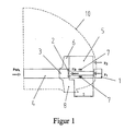
- the proposed collision protection device consists of FIGS. 1 and 2 a central buffer coupling 1, which at a predetermined breaking point 2 on the head support 3 of the base frame 4 is attached, from energy absorbing elements 5, each side of the central buffer coupling 1 between the lower edge of the head carrier 3 and the Rammschutzkonstrutation 6 extensively supported on the base frame 4, from at least one, the deflection of the central buffer coupling 1 limiting vertical stop 7, which is supported on the energy absorption elements 5, from an underrun protection 8, which in operative connection with the head support 3 and the Rammschutzkonstrutation 6 stands as well as from a guide shaft 9, the unhindered Retreating the central buffer coupling 1 after the failure of the predetermined breaking point. 2 allows.
- the known middle buffer coupling 1 in the embodiment allows coupling speeds according to the operational requirements of the operator (first Speed level). In the event of overshoots (exceeding the permissible coupling speed), e.g. In shunting accidents, the damage remains up to a higher Impingement speed (second speed level) on a compression tube in the coupling beam and an easily replaceable part of the headliner 10 at the vehicle end limited. Are the strokes of the central buffer coupling at even higher collision speeds 1 exhausted, this deviates after the response of the predetermined breaking point. 2 in a conventional manner in the guide shaft 9 of the base frame 4 back.
- the energy absorption elements 5 come with the Kollisionskontrahenten in Contact and are plastically compressed.
- the energy absorption elements 5 extend in the vertical direction approximately from the lower edge of the head carrier 3 to the upper edge of the Rammschutzkonstrutation 6. This arrangement ensures a good protective effect in collisions with similar vehicles or larger extraneous obstacles.
- the energy absorption elements 5 come in these cases in a conventional manner only after the failure of the predetermined breaking point 2 and the retreat of the central buffer coupling 1 in the guide shaft 9 to the effect.
- the breaking force F B of the predetermined breaking point 2 and the total deformation resistance F 1 + F 2 of the energy absorption elements 5 are dimensioned such that the force F wk which can be borne by the wagon body is not exceeded (F B ⁇ F Wk and F 1 + F 2 ⁇ F Wk ) ,
- the climbing is avoided by the large contact area at the front of the energy absorbing elements 5, their defined resistance to deformation and the small vertical difference between the vehicle's center of gravity (inertial force) and the impact force of the impact force.
- the arrangement of the central buffer coupling 1 and the energy absorption elements 5 designed for collisions with similar vehicles and extraneous obstacles has, in the case of collision with vehicles equipped with side buffers, the consequence that parallel effects of central buffer coupling 1 and energy absorption elements 5 can occur. There is a risk of overloading the body structure.
- This disadvantage is overcome here by the energy absorption elements 5 are arranged so that they deform when colliding with side buffer vehicles predominantly locally in the region of the penetrating buffer, wherein the resistance force F 1 of the energy absorption elements 5 in the local deformation and the breaking force F B of the predetermined breaking point 2 at the central buffer coupling 1 are dimensioned such that the force which can be borne by the car body is not exceeded (FIG.
- an underride guard 8 is arranged in operative connection with the head carrier 3 and the ram protection structure 6 below the head carrier 3 or the energy absorption elements 5. The front edge of the underrun protection 8 is set back from the front edge of the energy absorption elements 5 by the amount of the intended compression length S of the energy absorption elements 5, so that a parallel action of the energy absorption elements 5 and the underrun protection 8 is excluded.
- central buffer coupling 1 and energy absorbing elements 5 before the actual supporting vehicle frame allows a limitation of Vehicle damage to these components and to the front parts of the head fairing 10 up to a defined collision speed (third speed level).
Landscapes
- Engineering & Computer Science (AREA)
- Mechanical Engineering (AREA)
- Life Sciences & Earth Sciences (AREA)
- Wood Science & Technology (AREA)
- Transportation (AREA)
- Vibration Dampers (AREA)
- Train Traffic Observation, Control, And Security (AREA)
- Vehicle Body Suspensions (AREA)
- Air Bags (AREA)
Applications Claiming Priority (2)
| Application Number | Priority Date | Filing Date | Title |
|---|---|---|---|
| DE19817861 | 1998-04-22 | ||
| DE19817861A DE19817861C2 (de) | 1998-04-22 | 1998-04-22 | Kollisionsschutzeinrichtung für Schienenfahrzeuge |
Publications (2)
| Publication Number | Publication Date |
|---|---|
| EP0952062A1 EP0952062A1 (de) | 1999-10-27 |
| EP0952062B1 true EP0952062B1 (de) | 2005-08-31 |
Family
ID=7865362
Family Applications (1)
| Application Number | Title | Priority Date | Filing Date |
|---|---|---|---|
| EP99107605A Expired - Lifetime EP0952062B1 (de) | 1998-04-22 | 1999-04-16 | Kollisionsschutzeinrichtung für Schienenfahrzeuge |
Country Status (6)
| Country | Link |
|---|---|
| EP (1) | EP0952062B1 (cs) |
| AT (1) | ATE303276T1 (cs) |
| CZ (1) | CZ291299B6 (cs) |
| DE (2) | DE19817861C2 (cs) |
| PL (1) | PL193974B1 (cs) |
| SK (1) | SK285740B6 (cs) |
Cited By (1)
| Publication number | Priority date | Publication date | Assignee | Title |
|---|---|---|---|---|
| CN105980230A (zh) * | 2014-02-11 | 2016-09-28 | 西门子公司 | 用于轨道车辆的防爬设备 |
Families Citing this family (8)
| Publication number | Priority date | Publication date | Assignee | Title |
|---|---|---|---|---|
| DE10126483A1 (de) * | 2001-05-31 | 2002-12-05 | Scharfenbergkupplung Gmbh & Co | Energieverzehreinrichtung für die Stirnseite von Schienenfahrzeugen |
| DE10155257B4 (de) * | 2001-11-09 | 2008-02-21 | Alstom Lhb Gmbh | Kollisionsschutzeinrichtung für Schienenfahrzeuge |
| DE102004016216A1 (de) * | 2004-04-01 | 2005-10-20 | Siemens Ag | Wagenkasten eines Schienenfahrzeuges mit einer Vorrichtung zur gezielten Absorption von Kollisionsenergie |
| FR2879549B1 (fr) * | 2004-12-22 | 2007-02-09 | Alstom Transport Sa | Dispositif absorbeur de chocs pour vehicule ferroviaire |
| ITTO20060863A1 (it) | 2006-12-04 | 2008-06-05 | Ansaldobreda Spa | Carrozza di testa di un treno provvista di una struttura frontale che assorbe energia in caso di collisione |
| WO2011099268A1 (ja) | 2010-02-09 | 2011-08-18 | 川崎重工業株式会社 | 鉄道車両の車両装備品保護構造 |
| AT510958B1 (de) * | 2011-06-16 | 2012-08-15 | Siemens Ag Oesterreich | Anordnung zur umlenkung einer durch das versagen einer überlastsicherung im zuge eines zusammenstosses abgetrennten mittelpufferkupplung eines schienenfahrzeugs |
| FR3140605A1 (fr) * | 2022-10-11 | 2024-04-12 | Alstom Holdings | Caisse de véhicule ferroviaire et véhicule associé |
Family Cites Families (9)
| Publication number | Priority date | Publication date | Assignee | Title |
|---|---|---|---|---|
| DE635018C (de) * | 1933-01-14 | 1936-09-14 | Curt Stedefeld Dipl Ing | Stromlinienfoermiger Kopfteil mit zurueckliegendem Fuehrerstandsaufbau fuer Triebwagen mit hohen Geschwindigkeiten |
| FR2238341A5 (en) * | 1973-07-19 | 1975-02-14 | Alsthom | Bellows type vehicle shock absorber - shape of individual elements maintained between given limits |
| FI55632C (fi) * | 1978-03-20 | 1979-09-10 | Turunen Pekka J | Saekerhetsbuffert foer spaorbunden trafik |
| DE3632578A1 (de) * | 1986-09-25 | 1988-04-07 | Waggon Union Gmbh | Pufferstoss-energieverzehreinrichtung |
| FR2698840B1 (fr) * | 1992-12-08 | 1995-02-24 | Dietrich & Cie De | Véhicule ferroviaire à cabine de conduite comportant une structure absorbeuse d'énergie. |
| DE19502217C2 (de) * | 1995-01-25 | 1997-08-28 | Deutsche Waggonbau Ag | Energieverzehrsystem für Nahverkehrs-Schienenfahrzeuge, insbesondere für Stadtschnellbahnen |
| FR2747633B1 (fr) * | 1996-04-19 | 2003-01-31 | Alstom Ddf | Vehicule ferroviaire a cabine de conduite comportant une structure absorbeuse d'energie a deformation progressive |
| DE19654993A1 (de) * | 1996-09-10 | 1998-06-25 | Deutsche Waggonbau Ag | Untergestellvorbau mit Energieumwandlungssystem für Schienenfahrzeuge mit Mittelpufferkupplung |
| DE19720329C1 (de) * | 1997-05-15 | 1998-11-05 | Abb Daimler Benz Transp | Schienenfahrzeug mit Stoßverzehrelementeinrichtung |
-
1998
- 1998-04-22 DE DE19817861A patent/DE19817861C2/de not_active Expired - Fee Related
-
1999
- 1999-04-02 PL PL332362A patent/PL193974B1/pl unknown
- 1999-04-14 CZ CZ19991300A patent/CZ291299B6/cs not_active IP Right Cessation
- 1999-04-16 AT AT99107605T patent/ATE303276T1/de active
- 1999-04-16 EP EP99107605A patent/EP0952062B1/de not_active Expired - Lifetime
- 1999-04-16 DE DE59912477T patent/DE59912477D1/de not_active Expired - Lifetime
- 1999-04-22 SK SK526-99A patent/SK285740B6/sk not_active IP Right Cessation
Cited By (3)
| Publication number | Priority date | Publication date | Assignee | Title |
|---|---|---|---|---|
| CN105980230A (zh) * | 2014-02-11 | 2016-09-28 | 西门子公司 | 用于轨道车辆的防爬设备 |
| US9802628B2 (en) | 2014-02-11 | 2017-10-31 | Siemens Aktiengesellschaft | Anti-climbing protection apparatus for a rail vehicle |
| CN105980230B (zh) * | 2014-02-11 | 2018-05-22 | 西门子公司 | 用于轨道车辆的防爬设备 |
Also Published As
| Publication number | Publication date |
|---|---|
| CZ130099A3 (cs) | 1999-11-17 |
| CZ291299B6 (cs) | 2003-01-15 |
| SK285740B6 (sk) | 2007-07-06 |
| DE19817861C2 (de) | 2001-09-06 |
| ATE303276T1 (de) | 2005-09-15 |
| DE59912477D1 (de) | 2005-10-06 |
| PL332362A1 (en) | 1999-10-25 |
| DE19817861A1 (de) | 1999-10-28 |
| EP0952062A1 (de) | 1999-10-27 |
| PL193974B1 (pl) | 2007-04-30 |
| SK52699A3 (en) | 2000-01-18 |
Similar Documents
| Publication | Publication Date | Title |
|---|---|---|
| DE69404205T2 (de) | Stossdämpfende Vorrichtung | |
| EP1312527B1 (de) | Gelenkanordnung | |
| EP1232083B1 (de) | Schienenfahrzeug zur personenbeförderung, insbesondere für den nahverkehr | |
| EP2325058A2 (de) | Stoßfängeranordnung | |
| CH644805A5 (de) | Wiegebalkenloses drehgestell mit luftfederung fuer schienenfahrzeuge. | |
| EP0952062B1 (de) | Kollisionsschutzeinrichtung für Schienenfahrzeuge | |
| EP0952063B1 (de) | Sicherheitseinrichtung für Fahrzeugführer von Schienenfahrzeugen | |
| EP1310416B1 (de) | Kollisionsschutzeinrichtung für Schienenfahrzeuge | |
| EP1633615B1 (de) | Aufkletterschutz für eisenbahnwagen | |
| DE10121354A1 (de) | Vorderwagen für ein Kraftfahrzeug | |
| EP3640113A1 (de) | Energieaufnahmevorrichtung und schienenfahrzeug | |
| DE69306074T2 (de) | Ausschwenkbarer Stossfänger für Fahrzeuge | |
| DE19502217C2 (de) | Energieverzehrsystem für Nahverkehrs-Schienenfahrzeuge, insbesondere für Stadtschnellbahnen | |
| DE19532858A1 (de) | Sicherheitsstoßstange für Personenkraftwagen | |
| EP3560787B1 (de) | Schienenfahrzeug | |
| EP3771609B1 (de) | Hülsenpuffer mit abschnittsweise ummanteltem stössel | |
| DE102021003717A1 (de) | Kraftfahrzeug mit Aufprallschutzsystem | |
| EP2193970B1 (de) | Stoßeinrichtung für ein Schienenfahrzeug | |
| DE19855830C1 (de) | Kollisionsschutzeinrichtung für spurgeführte Stadtverkehrsfahrzeuge | |
| EP0857634B1 (de) | Schienengebundener Güterwagen, insbesondere Kesselwagen | |
| DE102024104951A1 (de) | Beweglicher Front-Unterfahrschutz für geländegängige LKWs | |
| EP1186508B1 (de) | Fahrzeug mit einer Stoßenergie-Verzehreinrichtung | |
| EP4431360A1 (de) | Frontschürze für schienenfahrzeuge | |
| EP4574620A1 (de) | Gelenkanordnung zum gelenkigen verbinden von zwei benachbarten wagenkästen eines spurgeführten fahrzeuges | |
| DE20121562U1 (de) | Gelenkanordnung |
Legal Events
| Date | Code | Title | Description |
|---|---|---|---|
| PUAI | Public reference made under article 153(3) epc to a published international application that has entered the european phase |
Free format text: ORIGINAL CODE: 0009012 |
|
| AK | Designated contracting states |
Kind code of ref document: A1 Designated state(s): AT DE ES FI FR GB IT PT |
|
| AX | Request for extension of the european patent |
Free format text: AL;LT;LV;MK;RO;SI |
|
| 17P | Request for examination filed |
Effective date: 20000414 |
|
| AKX | Designation fees paid |
Free format text: AT DE ES FI FR GB IT PT |
|
| RAP1 | Party data changed (applicant data changed or rights of an application transferred) |
Owner name: DB REISE & TOURISTIK AG Owner name: DWA DEUTSCHE WAGGONBAU GMBH |
|
| 17Q | First examination report despatched |
Effective date: 20030512 |
|
| GRAP | Despatch of communication of intention to grant a patent |
Free format text: ORIGINAL CODE: EPIDOSNIGR1 |
|
| RAP1 | Party data changed (applicant data changed or rights of an application transferred) |
Owner name: DB REISE & TOURISTIK AG Owner name: BOMBARDIER TRANSPORTATION (BAHNTECHNOLOGIE) HOLDIN |
|
| GRAS | Grant fee paid |
Free format text: ORIGINAL CODE: EPIDOSNIGR3 |
|
| RAP1 | Party data changed (applicant data changed or rights of an application transferred) |
Owner name: DB FERNVERKEHR AG Owner name: BOMBARDIER TRANSPORTATION (BAHNTECHNOLOGIE) HOLDIN |
|
| GRAA | (expected) grant |
Free format text: ORIGINAL CODE: 0009210 |
|
| AK | Designated contracting states |
Kind code of ref document: B1 Designated state(s): AT DE ES FI FR GB IT PT |
|
| PG25 | Lapsed in a contracting state [announced via postgrant information from national office to epo] |
Ref country code: FI Free format text: LAPSE BECAUSE OF FAILURE TO SUBMIT A TRANSLATION OF THE DESCRIPTION OR TO PAY THE FEE WITHIN THE PRESCRIBED TIME-LIMIT Effective date: 20050831 |
|
| REG | Reference to a national code |
Ref country code: GB Ref legal event code: FG4D Free format text: NOT ENGLISH |
|
| REF | Corresponds to: |
Ref document number: 59912477 Country of ref document: DE Date of ref document: 20051006 Kind code of ref document: P |
|
| PG25 | Lapsed in a contracting state [announced via postgrant information from national office to epo] |
Ref country code: ES Free format text: LAPSE BECAUSE OF FAILURE TO SUBMIT A TRANSLATION OF THE DESCRIPTION OR TO PAY THE FEE WITHIN THE PRESCRIBED TIME-LIMIT Effective date: 20051212 |
|
| GBT | Gb: translation of ep patent filed (gb section 77(6)(a)/1977) |
Effective date: 20051220 |
|
| PG25 | Lapsed in a contracting state [announced via postgrant information from national office to epo] |
Ref country code: PT Free format text: LAPSE BECAUSE OF FAILURE TO SUBMIT A TRANSLATION OF THE DESCRIPTION OR TO PAY THE FEE WITHIN THE PRESCRIBED TIME-LIMIT Effective date: 20060222 |
|
| ET | Fr: translation filed | ||
| PLBE | No opposition filed within time limit |
Free format text: ORIGINAL CODE: 0009261 |
|
| STAA | Information on the status of an ep patent application or granted ep patent |
Free format text: STATUS: NO OPPOSITION FILED WITHIN TIME LIMIT |
|
| 26N | No opposition filed |
Effective date: 20060601 |
|
| PGFP | Annual fee paid to national office [announced via postgrant information from national office to epo] |
Ref country code: IT Payment date: 20120424 Year of fee payment: 14 |
|
| PG25 | Lapsed in a contracting state [announced via postgrant information from national office to epo] |
Ref country code: IT Free format text: LAPSE BECAUSE OF NON-PAYMENT OF DUE FEES Effective date: 20130416 |
|
| REG | Reference to a national code |
Ref country code: FR Ref legal event code: PLFP Year of fee payment: 17 |
|
| PGFP | Annual fee paid to national office [announced via postgrant information from national office to epo] |
Ref country code: DE Payment date: 20150421 Year of fee payment: 17 Ref country code: GB Payment date: 20150420 Year of fee payment: 17 |
|
| PGFP | Annual fee paid to national office [announced via postgrant information from national office to epo] |
Ref country code: FR Payment date: 20150421 Year of fee payment: 17 Ref country code: AT Payment date: 20150421 Year of fee payment: 17 |
|
| REG | Reference to a national code |
Ref country code: DE Ref legal event code: R119 Ref document number: 59912477 Country of ref document: DE |
|
| REG | Reference to a national code |
Ref country code: AT Ref legal event code: MM01 Ref document number: 303276 Country of ref document: AT Kind code of ref document: T Effective date: 20160416 |
|
| GBPC | Gb: european patent ceased through non-payment of renewal fee |
Effective date: 20160416 |
|
| REG | Reference to a national code |
Ref country code: FR Ref legal event code: ST Effective date: 20161230 |
|
| PG25 | Lapsed in a contracting state [announced via postgrant information from national office to epo] |
Ref country code: GB Free format text: LAPSE BECAUSE OF NON-PAYMENT OF DUE FEES Effective date: 20160416 Ref country code: DE Free format text: LAPSE BECAUSE OF NON-PAYMENT OF DUE FEES Effective date: 20161101 Ref country code: FR Free format text: LAPSE BECAUSE OF NON-PAYMENT OF DUE FEES Effective date: 20160502 |
|
| PG25 | Lapsed in a contracting state [announced via postgrant information from national office to epo] |
Ref country code: AT Free format text: LAPSE BECAUSE OF NON-PAYMENT OF DUE FEES Effective date: 20160416 |