EP0951968A2 - Bestückungsgerät - Google Patents
Bestückungsgerät Download PDFInfo
- Publication number
- EP0951968A2 EP0951968A2 EP99303077A EP99303077A EP0951968A2 EP 0951968 A2 EP0951968 A2 EP 0951968A2 EP 99303077 A EP99303077 A EP 99303077A EP 99303077 A EP99303077 A EP 99303077A EP 0951968 A2 EP0951968 A2 EP 0951968A2
- Authority
- EP
- European Patent Office
- Prior art keywords
- robot
- article
- bolt
- picking
- holdable
- Prior art date
- Legal status (The legal status is an assumption and is not a legal conclusion. Google has not performed a legal analysis and makes no representation as to the accuracy of the status listed.)
- Withdrawn
Links
Images


Classifications
-
- B—PERFORMING OPERATIONS; TRANSPORTING
- B25—HAND TOOLS; PORTABLE POWER-DRIVEN TOOLS; MANIPULATORS
- B25J—MANIPULATORS; CHAMBERS PROVIDED WITH MANIPULATION DEVICES
- B25J9/00—Programme-controlled manipulators
- B25J9/16—Programme controls
- B25J9/1694—Programme controls characterised by use of sensors other than normal servo-feedback from position, speed or acceleration sensors, perception control, multi-sensor controlled systems, sensor fusion
- B25J9/1697—Vision controlled systems
-
- B—PERFORMING OPERATIONS; TRANSPORTING
- B25—HAND TOOLS; PORTABLE POWER-DRIVEN TOOLS; MANIPULATORS
- B25J—MANIPULATORS; CHAMBERS PROVIDED WITH MANIPULATION DEVICES
- B25J9/00—Programme-controlled manipulators
- B25J9/16—Programme controls
- B25J9/1679—Programme controls characterised by the tasks executed
- B25J9/1687—Assembly, peg and hole, palletising, straight line, weaving pattern movement
-
- G—PHYSICS
- G05—CONTROLLING; REGULATING
- G05B—CONTROL OR REGULATING SYSTEMS IN GENERAL; FUNCTIONAL ELEMENTS OF SUCH SYSTEMS; MONITORING OR TESTING ARRANGEMENTS FOR SUCH SYSTEMS OR ELEMENTS
- G05B2219/00—Program-control systems
- G05B2219/30—Nc systems
- G05B2219/37—Measurements
- G05B2219/37555—Camera detects orientation, position workpiece, points of workpiece
-
- G—PHYSICS
- G05—CONTROLLING; REGULATING
- G05B—CONTROL OR REGULATING SYSTEMS IN GENERAL; FUNCTIONAL ELEMENTS OF SUCH SYSTEMS; MONITORING OR TESTING ARRANGEMENTS FOR SUCH SYSTEMS OR ELEMENTS
- G05B2219/00—Program-control systems
- G05B2219/30—Nc systems
- G05B2219/37—Measurements
- G05B2219/37563—Ccd, tv camera
-
- G—PHYSICS
- G05—CONTROLLING; REGULATING
- G05B—CONTROL OR REGULATING SYSTEMS IN GENERAL; FUNCTIONAL ELEMENTS OF SUCH SYSTEMS; MONITORING OR TESTING ARRANGEMENTS FOR SUCH SYSTEMS OR ELEMENTS
- G05B2219/00—Program-control systems
- G05B2219/30—Nc systems
- G05B2219/37—Measurements
- G05B2219/37572—Camera, tv, vision
-
- G—PHYSICS
- G05—CONTROLLING; REGULATING
- G05B—CONTROL OR REGULATING SYSTEMS IN GENERAL; FUNCTIONAL ELEMENTS OF SUCH SYSTEMS; MONITORING OR TESTING ARRANGEMENTS FOR SUCH SYSTEMS OR ELEMENTS
- G05B2219/00—Program-control systems
- G05B2219/30—Nc systems
- G05B2219/40—Robotics, robotics mapping to robotics vision
- G05B2219/40053—Pick 3-D object from pile of objects
Definitions
- the present invention relates to an automation technology for handling articles such as assembly workpieces in a factory or other places. More particularly, it relates to an apparatus capable of picking up articles one by one by using an industrial robot (hereinafter referred to as a robot) when many articles are placed in a disorderly piled-up manner on a table or on an article placing surface of a box or the like.
- a robot industrial robot
- a problem with the conventional technology is that it is very difficult for the robot to hold and pick up an article one by one from many articles piled up disorderly.
- this picking-up work is especially difficuft to do.
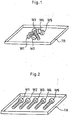
- the workpieces W1 to W5 are lined up or positioned so as to preclude the lapping before the picking-up work is performed by the robot as shown in Fig. 2. If the visual sensor is used, the decreased accuracy of lining-up or positioning of the workpieces W1 to W5 is allowed, and in some cases, some lapping of the workpieces is also allowed.
- An object of the present invention is to provide an apparatus capable of picking up articles exactly one by one from many piled-up articles without a manual operation for lining-up or positioning the articles and without using any special lining-up/positioning mechanism.
- the piled-up articles are loosened (including the decreasing of the degree of pileup of articles at least partially and the elimination of the pileup) by directly or indirectly giving a proper physical action to a group of articles, and the loosened article can be picked up one by one by a robot.
- the article picking-up apparatus in accordance with the present invention comprises a robot; articles placing means; loosening means having a function of giving a physical action to a group of articles mounted on said articles placing means in a piled-up state to loosen the piled-up state; and a visual sensor which searches for a group of articles on the articles placing means to find at least one holdable article that can be held by the robot in accordance with a predetermined criterion, and obtains data concerning the position of the holdable article.
- the robot is operated so as to hold and pick up the holdable article by using the data concerning the position of the holdable article.
- the visual sensor either a two-dimensional visual sensor or a three-dimensional visual sensor may be used.
- criterion an isolated article which is not lapped over any another article is taken as a holdable article. Also, as another example of criterion, one isolated article or an isolated small set consisting of a certain number ("N" number) or less articles contacting with each other is taken to be a set of holdable articles. The latter criterion is suitable to the picking-up apparatus using a three-dimensional visual sensor.
- the aforementioned value of N (for example, five) is selected as a value such that the robot can pick up individual articles from the maximum N number of articles with the aid of the visual sensor even if they are in contact with each other or piled up.
- a group of articles to be picked up is subjected to a physical action.
- This physical action is typically an oscillating motion.
- a shaking device attached to the articles placing means or a robot to which an operation for oscillating the articles placing means is taught can be used
- loosening means of another type for giving a physical action to a group of articles a tool for loosening the piled-up articles is mounted to the robot. The robot is taught and operated so as to level the pile of a group of articles by using the tool to establish a state in which the articles are isolated or a state in which N number or less articles are in contact with each other.
- the lining-up or positioning of articles which have conventionally been needed before the holding and picking-up operation of robot is started, becomes unnecessary. Therefore, manpower or a special-purpose mechanism for lining up or positioning the articles can be saved. As a result, great advantages can be obtained in terms of work efficiency and economical cost.
- Fig. 3 is a schematic view showing a general arrangement of a system, which includes an article picking-up apparatus in accordance with the present invention, used in a first embodiment of the present invention.
- the articles to be picked up are a large number of bolts.
- five bolts are shown as an example, and the whole thereof is indicated by a bolt group W.
- the bolt group W is supplied by using a supply device (not shown) in such a manner as to be disorderly piled up on a placing surface PL of a tray TR.
- the tray TR is attached to a shaking device 1 so that a physical action is given to the bolt group W.
- the shaking device 1 When the shaking device 1 is operated, the tray TR is oscillated, so that the piled-up bolt group W is loosened or disentangled.
- a CCD camera 4 which has a field of view covering almost the whole of the tray TR, is provided at an appropriate place just above the tray TR, and a robot 2 (only the hand portion thereof is shown) is provided at an appropriate place near the tray TR.
- the robot 2 is equipped with a hand 3 suitable for holding the individual bolt.
- An image processing device 10 is connected to the camera 4. Both of the image processing device 10 and the camera 4 constitute a publicly known two-dimensional visual sensor.
- Reference character MO denotes a monitor display consisting of a liquid crystal display, a CRT, or the like attached to the image processing device 10, which can display images obtained by the camera 4 or images processed by the image processing device 10.
- Reference numeral 20 denotes a robot controller that is also used as a controller for the whole system.
- the robot controller 20 is connected to not only the robot 2 but also to the shaking device 1, the image processing device 10, and necessary external devices (for example, a mechanism for supplying the bolt group W to the tray TR).
- necessary external devices for example, a mechanism for supplying the bolt group W to the tray TR.
- the shaking device 1 oscillates the tray TR on command from the robot controller 20 to give an oscillating motion to the bolt group W.
- a type using an electromagnet and other types are publicly known. Therefore, the details are omitted.
- Robot controller 20
- the approach path and holding posture of the robot are corrected on the basis of the data concerning the position (including posture; the same also applies to the following) of a holdable bolt (in this embodiment, an isolated bolt; the details are described later) output from the visual sensor.
- a holdable bolt in this embodiment, an isolated bolt; the details are described later
- Fig. 4 is a block diagram showing a somewhat detailed configuration of the above-described system.
- the image processing device 10 has a central processing unit (hereinafter referred to as a CPU) 11.
- the CPU 11 connects with a frame memory (image memory) 12, a control software memory 13 configurated by a ROM, a program memory 14 configured by a RAM etc., a data memory 15 configured by nonvolatile RAM, a camera interface 16, an image processing processor 17, a communication interface 18, and a monitor interface 19 via a bus BS1.
- the communication interface 18 is connected to a communication interface 27 at the side of the robot controller 20, and signals representing data and commands are transferred via both of these interfaces.
- the camera 4 is connected to the camera interface 16.
- the monitor MO is connected to the monitor interface 19, so that the image captured by the camera 4, the image invoked from the frame memory 12, and the processed image (for example, a contour extract image) can be seen at an appropriate time.
- the image captured by the field of view of the camera 4 is converted into a variable density image by grey scale and stored in the frame memory 12.
- the image processing processor 17 has a function of processing the image stored in the frame memory 12 on command of the CPU 11.
- the control software memory 13 stores the following programs and related parameters:
- the image captured by the camera 4, the image invoked from the frame memory 12, and the processed image (for example, a contour extract image) can be seen on a display screen of the monitor MO at an appropriate time.
- the robot controller 20 has a central processing unit (CPU) 21.
- the CPU 21 connects with a ROM 22 for storing various control programs including a program for executing the processing for a picking-up operation, described later, a RAM 23 used for the temporary storage of calculation data etc., a nonvolatile memory 24 for storing teaching data and various parameters, a digital servo circuit 25 for controlling the individual axes of the robot body 2, a teaching panel 26 for performing manual operation, setting of coordinate system, position teaching, automatic operation (playback operation), etc. of the robot, and a general purpose signal interface 27 connected to the communication interface 18 at the side of the image processing device 10 via a bus BS2.
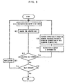
- Step S1 The bolt group W is photographed by the camera 4 on command from the robot controller 20, and the image is taken in the image processing device 10.
- Step S2 The taken-in image is analyzed, and an isolated bolt is searched for as a holdable bolt .
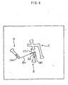
- the "isolated bolt” means a bolt such that the contour of one bolt is isolated (not lapped) from other bolt images on the screen as indicated by reference character A or B in Fig. 6.
- processing software for searching for an isolated bolt the publicly known pattern matching method is available.
- a standard pattern (here, a bolt contour image) representing the shape and size of an article to be searched for is stored in the image processing device 10 in advance, and the contour image element captured actually is compared with the standard pattern.
- the contour image elements A, B and C are compared with the standard pattern in succession.
- the contour image elements A and B are apparently capable of being lapped on the standard pattern (in other words, they can be matched with each other), so that they are judged to be the images of isolated bolts.
- the contour image element C is apparently incapable of being lapped on the standard pattern (in other words, they cannot be matched with each other), so that it is judged not to be the image of isolated bolt.
- Step S3 If at least one isolated bolt is found by the search of isolated bolt, the process proceeds to Step 54. If none is found, the process proceeds to Step S5. For example, in the case shown in Fig. 6, the process proceeds to Step S4.
- Step S4 The position of the found isolated bolt is detected, and a deviation from a standard position in teaching (indicated by vector T) is determined.
- a matrix ⁇ A homogeneous transformation matrix of four lines and four rows representing the relationship between vector A and vector T is determined.
- the rotation component of matrix ⁇ A represents the rotation on the XY plane, and the translation component thereof represents the translation on the XY plane.
- Step S5 The operation program having been taught in advance is started, and the robot 2 is operated to pick up isolated bolt A. At this time, the approach path and holding posture of robot are corrected in accordance with the data of matrix ⁇ A. After the operation is finished, the process returns to Step S1. Subsequently, steps S2 and S3 are executed again. If an isolated bolt remains, the process further proceeds from Step S3 to Step S4. In the case shown in Fig. 6, a matrix ⁇ B representing the relationship between vector B and vector T is determined this time.
- Step S6 In the case where no isolated bolt is found, two situations are assumed. That is to say, if a bolt image is present, but no isolated bolt is found (two or more bolts remain), the process proceeds to Step 57. If a bolt image itself is absent, the process is finished because this state means that all bolts have been picked up.
- Step S7 The shaking device 1 is operated for a fixed period of time to give an oscillating motion to the bolt group remaining on the tray TR at this point of time. After the operation of the shaking device 1 is stopped, the process returns to Step S1. In many cases, by the oscillating motion, some or all of the piled-up bolts are separated, and one or more isolated bolts are produced newly.
- Step S1 If an isolated bolt is produced newly, the processing cycle of Step S1 ⁇ Step S2 ⁇ Step S3 ⁇ Step S4 ⁇ Step S5 ⁇ Step S1 is executed. If the oscillating motion is insufficient and therefore no isolated bolt is produced newly, the process proceeds from Step S1 to Step S2 to Step S3 to Step S6 to Step S7, and the shaking device 1 is operated for a fixed period of time again, by which an oscillating motion is given. After the operation of the shaking device 1 is stopped, the process returns to Step S1. Subsequently, this cycle is repeated until the judgment result in Step S3 becomes Yes.
- Step S6 the judgment result in Step S6 is No, and the process is finished.
- a three-dimensional visual sensor is used in place of the two-dimensional visual sensor.
- a spotlight scanning type projector incorporating a spotlight projector capable of random scanning and a PSD position sensitive light detector) 50 is used as the three-dimensional visual sensor.
- the three-dimensional visual sensor of any one type for example, a slit light projector type three-dimensional visual sensor incorporating a slit light projector and a CCD camera may be used.
- a criterion for searching for a holdable bolt a criterion different from that of the first embodiment (the details are described later) is used.
- Fig. 7 is a schematic view showing a general arrangement of another system to which an article picking-up apparatus and method in accordance with the present invention are applied as the second embodiment of the present invention.
- the articles to be picked up are a large number of bolts.
- five bolts are shown as an example, and the whole thereof is indicated by a bolt group W.
- the bolt group W is supplied by using a supply device (not shown) in such a manner as to be disorderly piled up on a placing surface PL of a tray TR.
- the tray TR is attached to a shaking device 1 so that an oscillating motion is given to the bolt group W.
- a robot 2 (only the hand portion thereof is shown) is provided at an appropriate place near the tray TR, and a projector 40 which covers almost the whole of the tray TR as a scannable region and a PSD 50 equipped with a lens system LS are disposed at appropriate places around the tray TR.
- the projector 40 is made up of a laser beam source 41, deflectors 42 and 43 in which two rotating deflection axes intersect at right angles, and mirrors MX and MY attached to the deflectors 42 and 43, respectively.
- the driving control of the projector 40 and the processing of output signals of the PSD 50 are carried out by a projector driving/signal processing device 60.
- the projector 40, PSD 50, and projector driving/signal processing device 60, together with a part (software and hardware for searching for a holdable bolt in accordance with the criterion) of robot controller 30, constitute the publicly known three-dimensional visual sensor.
- the robot 2 is equipped with a hand 3 suitable for holding the individual bolt.
- Reference numeral 30 denotes a robot controller which is also used as a controller for the whole system.
- the robot controller 30 is connected not only to the robot 2 but also to a shaking device 1, the projector driving/signal processing device 60, and necessary external devices (for example, a mechanism for supplying the bolt group W to the tray TR).
- a shaking device 1 for example, a shaking device
- the projector driving/signal processing device 60 for example, a mechanism for supplying the bolt group W to the tray TR.
- the shaking device 1 is the same as that of the first embodiment. It oscillates the tray TR on command from the robot controller 30 to give an oscillating motion to the bolt group W.
- Three-dimensional visual sensor is a three-dimensional visual sensor
- the spot beam L1 can perform scanning in a desired pattern by programming the timerelated change pattern of the voltage commands (Vx, Vy).
- the spot beam L1 incident on a certain incident position P at any point of time produces a luminescent spot.
- This luminescent spot is detected by point Q on the light intercepting face of the PSD 50 via the lens system LS.
- the PSD 50 may be of a one-dimensional type. As the direct output of the PSD 50, two currents il and i2 according to the one-dimensional position of point Q are output. They pass through a publicly known analog signal processing circuit, and are converted into an output signal Vq representing the one-dimensional position of point Q.
- the three-dimensional position of the incident position P is determined by solving, as simultaneous equations, the equation of straight line representing the spot beam L1 specified by (Vx, Vy) and the conditional expression that gives the output signal Vq for point Q.
- Robot controller 30
- the teaching may be performed by placing a single bolt lying in a standard posture at a standard position on the tray TR and by making the robot controller 20 store the picking-up operation by using a teaching playback system.
- the approach path and holding posture of the robot are corrected on the basis of the data concerning the position of a holdable bolt (the details are described later) output from the three-dimensional visual sensor.
- Fig. 8 is block diagram showing a somewhat detailed configuration of the system in the second embodiment.
- the robot controller 30 has a CPU 31.
- the CPU 31 connects with a ROM 32 for storing various control programs, a RAM 33 used for the temporary storage of calculation data etc., a nonvolatile memory 34 for storing taught data and various parameters, a digital servo circuit 35 for controlling the individual axes of the robot body 2, a teaching panel 36 for performing manual operation, setting of coordinate system, position teaching, automatic operation (playback operation), etc. of the robot, and an input-output device (I/O) 37 via a bus BS.
- the control program includes programs for executing the search for a holdable bolt, the detection of position of the holdable bolt, and the picking-up operation of the holdable bolt by means of the robot 2 (the details of processing will be described later).
- the input-output device (1/O) 37 is connected to a projector driving section 61 and a PSD detection signal processing section 62 of the projector driving/signal processing device 60.
- the projector driving section 61 and the PSD detection signal processing section 62 each have a required CPU, memories, input-output device, and the like.
- the former is connected to the projector 40 to control the driving of the laser beam source 41 and the deflectors (galvanometers) 42 and 43, and the latter processes the output signals of the PSD 50, and sends signal Vq representing the position of detection point Q to the robot controller 30.
- the processing such as the acquisition of three-dimensional position data based on the voltage commands Vx, Vy, Vq and the subsequent search for a holdable bolt is performed in the robot controller 30.
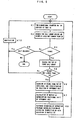
- Step K2 As a first step for searching for an isolated small set including holdable bolts, as shown in Fig. 11, a bolt group such that the occupied area (area surrounded by reference characters a,b,c,... s,t,u) is not larger than the reference value 3S is searched for.
- S is a reference value approximately representing an area occupied by a single bolt, and it is preferable that the optimum value be finely adjusted by tuning, the rule of thumb, etc.
- Sis set to be smallish a set consisting of four or more bolts can easily be excluded (that is, it is not judged to be an isolated small set).
- Step K3 If at least one bolt group having an occupied area not larger than 3S is found in Step K2, the process proceeds to Step K4. If none is found, the process proceeds to Step K9.
- Step K4 Atop (a point that gives the maximum Z-axis value) of the bolt groups is searched for based on the three-dimensional position data concerning the found bolt group.
- Step K5 As shown in Fig. 12, if the top height is not larger than the reference value 3d, it is judged to be an isolated small set including holdable bolts, and the process proceeds to Step K6. If the top height exceeds the reference value 3d, it is judged that the bolt group consists of bolts piled up over and over again and is not a small bolt group including holdable bolts, and the process proceeds to Step K10.
- d is a reference value approximately representing a diameter (a height when the bolt is placed horizontally) of a single bolt, and it is preferable that the optimum value be finely adjusted by tuning, the rule of thumb, etc. Generally, if d is set to be smallish, a set consisting of four or more bolts can easily be excluded.
- the criterion in this embodiment is used for searching for an "isolated small set" from both of the viewpoints of occupied area and top height.
- Step K6 As shown in Fig. 13, a ridge extending from the top is scanned by a spotlight, and the position data concerning the ridge is collected. Then, vector H representing the position of an uppermost bolt H is determined Generally, the Z component of vector H is not zero.
- Step K7 A matrix ⁇ H (homogeneous transformation matrix of four lines and four rows) representing a deviation of vector H5 from a standard position (indicated by vector T) at the time of teaching is determined. It is to be noted that vector T lies on the XY plane, but vector H does not lie on the XY plane.
- the rotation component of matrix ⁇ H represents the rotation in the three-dimensional space, and the translation component thereof represents the translation in the three-dimensional space.
- Step K8 The operation program having been taught in advance is started, and the robot 2 is operated to pick up uppermost bolt H. At this time, the approach path and holding posture of robot are corrected in accordance with the data of matrix ⁇ H. After the operation is finished, the process returns to Step K1.
- Step S2 and the subsequent steps are executed again. If an isolated small set remains, Step K8 is reached again, and the next bolt (for example, bolt I in Fig. 13) is picked up.
- Step K9 As a case where the judgment result in Step K3 is No, two situations are assumed. That is to say, if the bolt image is present but no isolated small set is found (several or more bolts remain), the process proceeds to Step K10. If the bolt image itself is absent, the process is finished because this state means that all bolts have been picked up.
- Step 10 The shaking device 1 is operated for a fixed period of time to give an oscillating motion to the bolt group remaining on the tray TR at this point of time. After the operation of the shaking device 1 is stopped, the process returns to Step K1. In many cases, by the oscillating motion, some or all of the piled-up bolts are separated, and one or more isolated bolts are produced newly.
- Step K1 Step K2 ⁇ ... ⁇ Step K8 ⁇ Step K1 is executed. If the oscillating motion is insufficient and therefore no isolated small set is produced newly, the shaking device 1 is operated for a fixed period of time again through Step K2 ⁇ Step K3 ⁇ Step K9 or Step K2 ⁇ ... ⁇ Step K5, by which an oscillating motion is given. After the operation of the shaking device 1 is stopped, the process returns to Step K1. Subsequently, this cycle is repeated until the judgment results in Step K3 and Step K5 become Yes.
- Step K9 the judgment result in Step K9 is No, and the process is finished.
- the physical action applied to a group of articles to loosen the piled-up articles is an oscillating motion, and this oscillation motion is produced by the shaking device attached to the tray TR.
- the present invention is not limited to these examples.
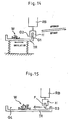
- the physical action may be applied by a robot RB (which may be the same as or separated from a robot for holding the article).
- a robot RB which may be the same as or separated from a robot for holding the article.
- the tray TR is supported elastically, and the approach operation to the edge of the tray TR, the operation for holding the edge of the tray TR by means of a hand H, the oscillating operation (for example, the reciprocating motion between G1 and G2) with the tray TR being held, the retreat operation, etc. are taught to the robot RB in advance.
- the robot RB may be equipped with a loosening member F such as a leveling plate or a brush-like leveling member to loosen the piled-up article group by using the loosening member F.
- a loosening member F such as a leveling plate or a brush-like leveling member to loosen the piled-up article group by using the loosening member F.
- an operation suitable for loosening the piled-up article group for example, the reciprocating motion between G3 and G4 is taught to the robot RB.
- an air gun AG may be provided near the tray TR to loosen the piled-up article group W by an air jet or jet of (or jet of any other gas) blown from the air gun AG.
- the broken line 100 in the figures indicates a cable 100 connecting the air gun AG to the robot controller 20 or 30 when the air gun AG is used.
- the air gun AG is operated on command from the robot controller 20 or 30. It may be used together with the shaking device 1 (switching operation, simultaneous operation, etc.) or may be used as a means for loosening substituting for the shaking device 1.
Landscapes
- Engineering & Computer Science (AREA)
- Robotics (AREA)
- Mechanical Engineering (AREA)
- Manipulator (AREA)
- Numerical Control (AREA)
- Automatic Assembly (AREA)
Applications Claiming Priority (2)
| Application Number | Priority Date | Filing Date | Title |
|---|---|---|---|
| JP12536898 | 1998-04-21 | ||
| JP10125368A JPH11300670A (ja) | 1998-04-21 | 1998-04-21 | 物品ピックアップ装置 |
Publications (2)
| Publication Number | Publication Date |
|---|---|
| EP0951968A2 true EP0951968A2 (de) | 1999-10-27 |
| EP0951968A3 EP0951968A3 (de) | 2003-07-02 |
Family
ID=14908410
Family Applications (1)
| Application Number | Title | Priority Date | Filing Date |
|---|---|---|---|
| EP99303077A Withdrawn EP0951968A3 (de) | 1998-04-21 | 1999-04-21 | Bestückungsgerät |
Country Status (3)
| Country | Link |
|---|---|
| US (1) | US6328523B1 (de) |
| EP (1) | EP0951968A3 (de) |
| JP (1) | JPH11300670A (de) |
Cited By (31)
| Publication number | Priority date | Publication date | Assignee | Title |
|---|---|---|---|---|
| WO2003064116A2 (en) * | 2002-01-31 | 2003-08-07 | Braintech Canada, Inc. | Method and apparatus for single camera 3d vision guided robotics |
| EP1391275A3 (de) * | 2002-08-23 | 2004-06-16 | Fanuc Ltd | Vorrichtung zur Handhabung von Werkstücken |
| WO2004052596A1 (en) * | 2002-12-10 | 2004-06-24 | Svensk Industriautomation Ab | Method and arrangement to avoid collision between a robot and its surroundings while picking details including a sensorsystem |
| US6816755B2 (en) | 2002-01-31 | 2004-11-09 | Braintech Canada, Inc. | Method and apparatus for single camera 3D vision guided robotics |
| EP1589483A2 (de) * | 2004-04-23 | 2005-10-26 | Fanuc Ltd | System zum Greifen von Objekten |
| EP1676679A2 (de) * | 2004-12-21 | 2006-07-05 | Fanuc Ltd | Robotische Steuereinheit zur Positionskorrektur einer Roboterhand mittels einem optischen Sensor |
| WO2007046763A1 (en) * | 2005-10-18 | 2007-04-26 | Morphic Technologies Aktiebolag (Publ.) | A method and an arrangement for locating and picking up objects from a carrier |
| US7336814B2 (en) | 2004-07-14 | 2008-02-26 | Braintech Canada, Inc. | Method and apparatus for machine-vision |
| EP1897663A2 (de) * | 2006-09-05 | 2008-03-12 | Adept Technology Inc. | Aufnahmesystem von in einem Behälter zufallspositionierten Objekten |
| EP1642853A3 (de) * | 2004-09-16 | 2008-03-19 | Fanuc Ltd | Handhabungsroboter |
| EP1710646A3 (de) * | 2005-03-12 | 2008-09-10 | Dorst Technologies GmbH & Co. KG | Verfahren und Vorrichtung zur Lageerkennung eines Formteils |
| WO2008154932A1 (en) * | 2007-06-18 | 2008-12-24 | Syddansk Universitet | Determining a robot path |
| EP1905548A3 (de) * | 2006-09-29 | 2009-01-28 | Fanuc Ltd | Vorrichtung zur Werkstückaufnahme |
| EP1862270A3 (de) * | 2006-05-29 | 2009-12-02 | Fanuc Ltd | Werkstückaufnahmevorrichtung und -verfahren |
| WO2010024795A1 (en) * | 2008-08-29 | 2010-03-04 | Abb Research Ltd. | Robotic picking of parts from a bin using force feedback |
| WO2010096850A1 (de) | 2009-02-26 | 2010-09-02 | Ih Tech Sondermaschinenbau U. Instandhaltung Gmbh | Verfahren und vorrichtung zum robotergesteuerten greifen und bewegen von objekten |
| US20100284608A1 (en) * | 2009-05-07 | 2010-11-11 | Marchesini Group S.P.A. | Feature-based segmentation method, for segmenting a plurality of loosely-arranged duplicate articles and a group for actuating the method for supplying a packaging machine |
| EP2253415A1 (de) * | 2008-03-17 | 2010-11-24 | Honda Motor Co., Ltd. | System zur ausrichtung eines werkstücks und verfahren zum bewegen eines werkstücks |
| CN102049778A (zh) * | 2009-10-26 | 2011-05-11 | 株式会社安川电机 | 机器人系统以及工件取出方法 |
| US7957583B2 (en) | 2007-08-02 | 2011-06-07 | Roboticvisiontech Llc | System and method of three-dimensional pose estimation |
| CN102785238A (zh) * | 2011-05-17 | 2012-11-21 | 株式会社安川电机 | 机器人系统 |
| US8437535B2 (en) | 2006-09-19 | 2013-05-07 | Roboticvisiontech Llc | System and method of determining object pose |
| CN104249371A (zh) * | 2013-06-28 | 2014-12-31 | 佳能株式会社 | 信息处理装置和信息处理方法 |
| US9008841B2 (en) | 2009-08-27 | 2015-04-14 | Abb Research Ltd. | Robotic picking of parts from a parts holding bin |
| CN105459115A (zh) * | 2015-12-17 | 2016-04-06 | 王玮 | 一种工业机器人 |
| CN105499953A (zh) * | 2016-01-12 | 2016-04-20 | 中国科学院自动化研究所 | 基于工业机器人的汽车发动机活塞、缸体装配系统及方法 |
| WO2018131001A1 (en) * | 2017-01-16 | 2018-07-19 | Tyco Electronics (Shanghai) Co. Ltd. | System and method for feeding diaphragm |
| WO2018131000A1 (en) * | 2017-01-16 | 2018-07-19 | Tyco Electronics (Shanghai) Co. Ltd. | System and method for feeding diaphragm |
| CN113840694A (zh) * | 2019-03-11 | 2021-12-24 | 右手机器人股份有限公司 | 拾取操作的物品扰动 |
| CN114286740A (zh) * | 2019-09-18 | 2022-04-05 | 株式会社富士 | 作业机器人以及作业系统 |
| EP4101584A1 (de) * | 2021-06-08 | 2022-12-14 | Dürr Assembly Products GmbH | Vorrichtung zum greifen länglicher befestigungselemente aus einem ungeordneten lager |
Families Citing this family (64)
| Publication number | Priority date | Publication date | Assignee | Title |
|---|---|---|---|---|
| JP3421608B2 (ja) * | 1999-04-08 | 2003-06-30 | ファナック株式会社 | 教示モデル生成装置 |
| DE19927251C2 (de) * | 1999-06-15 | 2001-05-17 | Siemens Ag | Vorrichtung zum Handhaben von Stückgütern |
| GB9926555D0 (en) * | 1999-11-09 | 2000-01-12 | Ishida Europ Mfg Ltd | Method and apparatus for orienting flexible walled articles |
| US6481560B2 (en) * | 2000-06-08 | 2002-11-19 | Christopher L. Kearney | Robotic feeding system |
| JP3782679B2 (ja) * | 2001-05-09 | 2006-06-07 | ファナック株式会社 | 干渉回避装置 |
| JP2003148914A (ja) * | 2001-11-08 | 2003-05-21 | Fanuc Ltd | 位置検出装置及び位置検出を利用した取出し装置 |
| US7746379B2 (en) * | 2002-12-31 | 2010-06-29 | Asset Intelligence, Llc | Sensing cargo using an imaging device |
| US20060115350A1 (en) * | 2003-01-15 | 2006-06-01 | Otto Weis | Device for automatically installing and reoving twistlocks |
| JP4441409B2 (ja) * | 2003-03-25 | 2010-03-31 | ローツェ株式会社 | ロボットシミュレーション装置、および、シミュレーションプログラム |
| US6900608B2 (en) | 2003-04-17 | 2005-05-31 | Automated Assemblies Corporation | Apparatus for controlling a motor |
| JP3745364B2 (ja) * | 2003-05-21 | 2006-02-15 | 松下電器産業株式会社 | 物品管理システム、物品管理サーバ |
| CA2535828C (en) * | 2003-08-15 | 2011-02-08 | Scape A/S | Computer-vision system for classification and spatial localization of bounded 3d-objects |
| JP2005111619A (ja) * | 2003-10-08 | 2005-04-28 | Tsubakimoto Chain Co | 物品配置方法、及び物品配置装置 |
| US20060083419A1 (en) * | 2004-10-18 | 2006-04-20 | Michael Carbaugh | Systems and methods for isolating parts |
| US20070140821A1 (en) * | 2005-12-19 | 2007-06-21 | Betzalel Robotics, Llc | Autonomous load/unload robot |
| FR2929481B1 (fr) * | 2008-03-26 | 2010-12-24 | Ballina Freres De | Procede et installation d'examen visiometrique de produits en defilement |
| CN102186638B (zh) * | 2008-08-29 | 2016-03-02 | Abb研究有限公司 | 在工业机器人的手臂末端处的工具的顺应装置 |
| EP2346649B1 (de) * | 2008-08-29 | 2020-07-29 | ABB Schweiz AG | Bin-picking-roboter mit mitteln zum bewegen der teile im behälter |
| IT1391349B1 (it) * | 2008-10-06 | 2011-12-13 | Ars S R L | Dispositivo alimentatore per robot, mezzi di automazione e simili. |
| US8559699B2 (en) * | 2008-10-10 | 2013-10-15 | Roboticvisiontech Llc | Methods and apparatus to facilitate operations in image based systems |
| CN102405447A (zh) | 2009-04-11 | 2012-04-04 | Abb股份公司 | 机器人系统 |
| JP5333344B2 (ja) * | 2009-06-19 | 2013-11-06 | 株式会社安川電機 | 形状検出装置及びロボットシステム |
| US8600552B2 (en) * | 2009-10-30 | 2013-12-03 | Honda Motor Co., Ltd. | Information processing method, apparatus, and computer readable medium |
| JP5685027B2 (ja) | 2010-09-07 | 2015-03-18 | キヤノン株式会社 | 情報処理装置、物体把持システム、ロボットシステム、情報処理方法、物体把持方法およびプログラム |
| KR101453234B1 (ko) | 2010-11-17 | 2014-10-22 | 미쓰비시덴키 가부시키가이샤 | 워크 취출 장치 |
| JP5767464B2 (ja) * | 2010-12-15 | 2015-08-19 | キヤノン株式会社 | 情報処理装置、情報処理装置の制御方法、およびプログラム |
| JP5533727B2 (ja) * | 2011-02-18 | 2014-06-25 | 株式会社安川電機 | ワークピッキングシステム |
| JP5835926B2 (ja) * | 2011-04-11 | 2015-12-24 | キヤノン株式会社 | 情報処理装置、情報処理装置の制御方法、およびプログラム |
| JP5266377B2 (ja) * | 2011-12-19 | 2013-08-21 | ファナック株式会社 | 物品の姿勢を修正する機能を備えた取出し装置 |
| JP5507595B2 (ja) * | 2012-02-17 | 2014-05-28 | ファナック株式会社 | ロボットを用いた物品組付け装置 |
| KR102056664B1 (ko) * | 2012-10-04 | 2019-12-17 | 한국전자통신연구원 | 센서를 이용한 작업 방법 및 이를 수행하는 작업 시스템 |
| DE102012221793B4 (de) * | 2012-11-28 | 2017-11-02 | Westcam Technologies Gmbh | Automatisches Verfahren zum Positionieren eines Prothesenzahnes |
| JP5765355B2 (ja) * | 2013-03-18 | 2015-08-19 | 株式会社安川電機 | ロボットピッキングシステム及び被加工物の製造方法 |
| JP2014205209A (ja) * | 2013-04-11 | 2014-10-30 | 三菱電機株式会社 | ロボットシステム、及びロボットシステムの制御方法 |
| US9785911B2 (en) | 2013-07-25 | 2017-10-10 | I AM Robotics, LLC | System and method for piece-picking or put-away with a mobile manipulation robot |
| US11348066B2 (en) | 2013-07-25 | 2022-05-31 | IAM Robotics, LLC | System and method for piece picking or put-away with a mobile manipulation robot |
| NL2011493C2 (en) * | 2013-09-25 | 2015-03-30 | Robert Vuurmans | Feeder device. |
| US9586320B2 (en) * | 2013-10-04 | 2017-03-07 | GM Global Technology Operations LLC | System and method for controlling a vision guided robot assembly |
| US10112303B2 (en) | 2013-10-25 | 2018-10-30 | Aleksandar Vakanski | Image-based trajectory robot programming planning approach |
| JP6301782B2 (ja) | 2014-08-27 | 2018-03-28 | ファナック株式会社 | 物品を種類毎に供給する物品供給装置 |
| JP6392587B2 (ja) | 2014-08-27 | 2018-09-19 | ファナック株式会社 | 物品を個別に供給する物品供給装置 |
| CN104346614B (zh) * | 2014-09-04 | 2018-06-01 | 四川农业大学 | 一种实景下的西瓜图像处理和定位方法 |
| JP2017074651A (ja) * | 2015-10-16 | 2017-04-20 | 株式会社特電 | ワークの自動供給方法 |
| EP3600795A1 (de) | 2017-03-30 | 2020-02-05 | Soft Robotics, Inc. | Benutzergestützte robotersteuersysteme |
| WO2018212190A1 (ja) * | 2017-05-15 | 2018-11-22 | Thk株式会社 | 把持システム |
| JPWO2018212194A1 (ja) * | 2017-05-15 | 2020-03-19 | Thk株式会社 | 把持システム |
| JP6453980B1 (ja) * | 2017-11-01 | 2019-01-16 | 三晶エムイーシー株式会社 | 部品供給装置 |
| ES2828307T3 (es) * | 2017-12-05 | 2021-05-26 | Guima Palfinger S A S | Sistema de detección para montaje en camiones |
| KR102317033B1 (ko) * | 2017-12-15 | 2021-10-25 | 한국전자기술연구원 | 로봇의 학습 데이터 수집 시스템 및 방법 |
| KR102565444B1 (ko) * | 2017-12-21 | 2023-08-08 | 삼성전자주식회사 | 객체를 식별하기 위한 장치 및 방법 |
| US10657419B2 (en) * | 2018-03-28 | 2020-05-19 | The Boeing Company | Machine vision and robotic installation systems and methods |
| JP7102241B2 (ja) * | 2018-06-14 | 2022-07-19 | ヤマハ発動機株式会社 | 機械学習装置及びこれを備えたロボットシステム |
| CN109040680A (zh) * | 2018-08-13 | 2018-12-18 | 昆山睿力得软件技术有限公司 | 一种用于产品装配的视觉引导系统 |
| CN110370268B (zh) * | 2018-09-11 | 2021-07-30 | 北京京东乾石科技有限公司 | 箱内拣选的方法、装置和系统 |
| KR102270958B1 (ko) * | 2018-11-20 | 2021-06-30 | 한양대학교 산학협력단 | 파지 로봇 및 목표 물체 파지를 위한 주변 물체 분리 방법 |
| US10926416B2 (en) * | 2018-11-21 | 2021-02-23 | Ford Global Technologies, Llc | Robotic manipulation using an independently actuated vision system, an adversarial control scheme, and a multi-tasking deep learning architecture |
| CN113015604B (zh) * | 2018-12-11 | 2024-03-08 | 株式会社富士 | 机器人控制系统及机器人控制方法 |
| WO2020206457A1 (en) | 2019-04-05 | 2020-10-08 | IAM Robotics, LLC | Autonomous mobile robotic systems and methods for picking and put-away |
| JP7289770B2 (ja) * | 2019-10-16 | 2023-06-12 | トヨタ紡織株式会社 | ピッキング装置 |
| US11613431B2 (en) * | 2020-04-30 | 2023-03-28 | Kuka Systems North America Llc | Fastener feeding system and method |
| JP7168709B2 (ja) * | 2021-02-26 | 2022-11-09 | 株式会社Fuji | ピックアップ装置 |
| CN113524187B (zh) * | 2021-07-20 | 2022-12-13 | 熵智科技(深圳)有限公司 | 一种工件抓取顺序的确定方法、装置、计算机设备及介质 |
| DE102022102720A1 (de) | 2022-02-04 | 2023-08-10 | Henrik Klag | Robotergesteuerte zuführeinrichtung |
| JP7383085B1 (ja) * | 2022-06-27 | 2023-11-17 | ヤマハ発動機株式会社 | ピッキング装置 |
Citations (6)
| Publication number | Priority date | Publication date | Assignee | Title |
|---|---|---|---|---|
| US3881605A (en) * | 1973-06-29 | 1975-05-06 | Ibm | Object orienting device to assist robot manipulator |
| JPH01110428A (ja) * | 1987-10-22 | 1989-04-27 | Honda Motor Co Ltd | ワークの位置決め装置 |
| JPH02117513A (ja) * | 1988-10-25 | 1990-05-02 | Shinko Electric Co Ltd | 振動部品供給機 |
| US5041907A (en) * | 1990-01-29 | 1991-08-20 | Technistar Corporation | Automated assembly and packaging system |
| WO1992003364A1 (en) * | 1990-08-25 | 1992-03-05 | Intelligent Automation Systems, Inc. | Programmable reconfigurable parts feeder |
| EP0667124A1 (de) * | 1994-01-13 | 1995-08-16 | Ethicon Inc. | Roboterprüfssystem für ein Gerät das Nadeln sortiert und versorgt |
Family Cites Families (11)
| Publication number | Priority date | Publication date | Assignee | Title |
|---|---|---|---|---|
| US4909376A (en) * | 1987-10-06 | 1990-03-20 | Western Technologies Automation, Inc. | Robotically controlled component feed mechanism visually monitoring part orientation |
| JP2917296B2 (ja) * | 1989-05-15 | 1999-07-12 | 日産自動車株式会社 | 視覚機能付作業装置 |
| GB2261069B (en) * | 1991-10-30 | 1995-11-01 | Nippon Denso Co | High speed picking system for stacked parts |
| JP2679490B2 (ja) * | 1991-11-08 | 1997-11-19 | 株式会社デンソー | 山積み部品の高速ピッキング装置 |
| JPH05228780A (ja) * | 1992-02-19 | 1993-09-07 | Daikin Ind Ltd | 把持対象ワークの把持位置教示方法 |
| JPH06144584A (ja) * | 1992-10-29 | 1994-05-24 | Daido Steel Co Ltd | 乱積みワーク取り出し装置 |
| JPH0753054A (ja) * | 1993-08-10 | 1995-02-28 | Mitsubishi Electric Corp | 自動荷卸し装置 |
| JP3225740B2 (ja) * | 1994-05-25 | 2001-11-05 | 株式会社デンソー | 山積み部品の高速ピッキング装置 |
| JP3375242B2 (ja) * | 1995-11-24 | 2003-02-10 | 豊田工機株式会社 | ロボットの物体認識方法及びその装置 |
| JPH11123681A (ja) | 1997-10-24 | 1999-05-11 | Mitsubishi Electric Corp | ピッキング装置およびピッキング方法 |
| US5853078A (en) * | 1998-02-13 | 1998-12-29 | Menziken Automation, Inc. | Vibrating feeder bowl with annular rotating disk feeder |
-
1998
- 1998-04-21 JP JP10125368A patent/JPH11300670A/ja active Pending
-
1999
- 1999-04-21 EP EP99303077A patent/EP0951968A3/de not_active Withdrawn
- 1999-04-21 US US09/295,364 patent/US6328523B1/en not_active Expired - Lifetime
Patent Citations (6)
| Publication number | Priority date | Publication date | Assignee | Title |
|---|---|---|---|---|
| US3881605A (en) * | 1973-06-29 | 1975-05-06 | Ibm | Object orienting device to assist robot manipulator |
| JPH01110428A (ja) * | 1987-10-22 | 1989-04-27 | Honda Motor Co Ltd | ワークの位置決め装置 |
| JPH02117513A (ja) * | 1988-10-25 | 1990-05-02 | Shinko Electric Co Ltd | 振動部品供給機 |
| US5041907A (en) * | 1990-01-29 | 1991-08-20 | Technistar Corporation | Automated assembly and packaging system |
| WO1992003364A1 (en) * | 1990-08-25 | 1992-03-05 | Intelligent Automation Systems, Inc. | Programmable reconfigurable parts feeder |
| EP0667124A1 (de) * | 1994-01-13 | 1995-08-16 | Ethicon Inc. | Roboterprüfssystem für ein Gerät das Nadeln sortiert und versorgt |
Non-Patent Citations (2)
| Title |
|---|
| PATENT ABSTRACTS OF JAPAN vol. 013, no. 327 (M-854), 24 July 1989 (1989-07-24) & JP 01 110428 A (HONDA MOTOR CO LTD), 27 April 1989 (1989-04-27) * |
| PATENT ABSTRACTS OF JAPAN vol. 014, no. 339 (M-1001), 23 July 1990 (1990-07-23) & JP 02 117513 A (SHINKO ELECTRIC CO LTD), 2 May 1990 (1990-05-02) * |
Cited By (56)
| Publication number | Priority date | Publication date | Assignee | Title |
|---|---|---|---|---|
| US8095237B2 (en) | 2002-01-31 | 2012-01-10 | Roboticvisiontech Llc | Method and apparatus for single image 3D vision guided robotics |
| WO2003064116A3 (en) * | 2002-01-31 | 2004-02-05 | Braintech Canada Inc | Method and apparatus for single camera 3d vision guided robotics |
| US6816755B2 (en) | 2002-01-31 | 2004-11-09 | Braintech Canada, Inc. | Method and apparatus for single camera 3D vision guided robotics |
| WO2003064116A2 (en) * | 2002-01-31 | 2003-08-07 | Braintech Canada, Inc. | Method and apparatus for single camera 3d vision guided robotics |
| EP1391275A3 (de) * | 2002-08-23 | 2004-06-16 | Fanuc Ltd | Vorrichtung zur Handhabung von Werkstücken |
| US7244093B2 (en) | 2002-08-23 | 2007-07-17 | Fanuc Ltd. | Object handling apparatus |
| WO2004052596A1 (en) * | 2002-12-10 | 2004-06-24 | Svensk Industriautomation Ab | Method and arrangement to avoid collision between a robot and its surroundings while picking details including a sensorsystem |
| EP1589483A2 (de) * | 2004-04-23 | 2005-10-26 | Fanuc Ltd | System zum Greifen von Objekten |
| EP1589483A3 (de) * | 2004-04-23 | 2006-05-31 | Fanuc Ltd | System zum Greifen von Objekten |
| CN1699033B (zh) * | 2004-04-23 | 2010-05-26 | 发那科株式会社 | 物体取出系统 |
| US7657346B2 (en) | 2004-04-23 | 2010-02-02 | Fanuc Ltd | Object picking system |
| US7336814B2 (en) | 2004-07-14 | 2008-02-26 | Braintech Canada, Inc. | Method and apparatus for machine-vision |
| EP1642853A3 (de) * | 2004-09-16 | 2008-03-19 | Fanuc Ltd | Handhabungsroboter |
| US7580773B2 (en) | 2004-09-16 | 2009-08-25 | Fanuc Ltd | Handling robot system |
| EP1676679A3 (de) * | 2004-12-21 | 2008-03-19 | Fanuc Ltd | Robotische Steuereinheit zur Positionskorrektur einer Roboterhand mittels einem optischen Sensor |
| EP1676679A2 (de) * | 2004-12-21 | 2006-07-05 | Fanuc Ltd | Robotische Steuereinheit zur Positionskorrektur einer Roboterhand mittels einem optischen Sensor |
| EP1710646A3 (de) * | 2005-03-12 | 2008-09-10 | Dorst Technologies GmbH & Co. KG | Verfahren und Vorrichtung zur Lageerkennung eines Formteils |
| WO2007046763A1 (en) * | 2005-10-18 | 2007-04-26 | Morphic Technologies Aktiebolag (Publ.) | A method and an arrangement for locating and picking up objects from a carrier |
| EP1862270A3 (de) * | 2006-05-29 | 2009-12-02 | Fanuc Ltd | Werkstückaufnahmevorrichtung und -verfahren |
| US7996114B2 (en) | 2006-05-29 | 2011-08-09 | Fanuc Ltd | Workpiece picking device and method |
| EP1897663A2 (de) * | 2006-09-05 | 2008-03-12 | Adept Technology Inc. | Aufnahmesystem von in einem Behälter zufallspositionierten Objekten |
| EP1897663A3 (de) * | 2006-09-05 | 2010-04-07 | Adept Technology Inc. | Aufnahmesystem von in einem Behälter zufallspositionierten Objekten |
| US8437535B2 (en) | 2006-09-19 | 2013-05-07 | Roboticvisiontech Llc | System and method of determining object pose |
| US7966094B2 (en) | 2006-09-29 | 2011-06-21 | Fanuc Ltd | Workpiece picking apparatus |
| EP1905548A3 (de) * | 2006-09-29 | 2009-01-28 | Fanuc Ltd | Vorrichtung zur Werkstückaufnahme |
| WO2008154932A1 (en) * | 2007-06-18 | 2008-12-24 | Syddansk Universitet | Determining a robot path |
| US7957583B2 (en) | 2007-08-02 | 2011-06-07 | Roboticvisiontech Llc | System and method of three-dimensional pose estimation |
| EP2253415A1 (de) * | 2008-03-17 | 2010-11-24 | Honda Motor Co., Ltd. | System zur ausrichtung eines werkstücks und verfahren zum bewegen eines werkstücks |
| EP2253415A4 (de) * | 2008-03-17 | 2013-03-20 | Honda Motor Co Ltd | System zur ausrichtung eines werkstücks und verfahren zum bewegen eines werkstücks |
| US9079308B2 (en) | 2008-08-29 | 2015-07-14 | Abb Research Ltd. | Robotic picking of parts from a bin |
| WO2010024795A1 (en) * | 2008-08-29 | 2010-03-04 | Abb Research Ltd. | Robotic picking of parts from a bin using force feedback |
| WO2010096850A1 (de) | 2009-02-26 | 2010-09-02 | Ih Tech Sondermaschinenbau U. Instandhaltung Gmbh | Verfahren und vorrichtung zum robotergesteuerten greifen und bewegen von objekten |
| US20100284608A1 (en) * | 2009-05-07 | 2010-11-11 | Marchesini Group S.P.A. | Feature-based segmentation method, for segmenting a plurality of loosely-arranged duplicate articles and a group for actuating the method for supplying a packaging machine |
| US8467597B2 (en) * | 2009-05-07 | 2013-06-18 | Marchesini Group S.P.A. | Feature-based segmentation method, for segmenting a plurality of loosely-arranged duplicate articles and a group for actuating the method for supplying a packaging machine |
| US9008841B2 (en) | 2009-08-27 | 2015-04-14 | Abb Research Ltd. | Robotic picking of parts from a parts holding bin |
| EP2314425A3 (de) * | 2009-10-26 | 2012-01-04 | Kabushiki Kaisha Yaskawa Denki | Robotersystem und Werkstückaufnahmeverfahren |
| CN102049778A (zh) * | 2009-10-26 | 2011-05-11 | 株式会社安川电机 | 机器人系统以及工件取出方法 |
| US8660685B2 (en) | 2009-10-26 | 2014-02-25 | Kabushiki Kaisha Yaskawa Denki | Robot system and workpiece picking method |
| CN102785238A (zh) * | 2011-05-17 | 2012-11-21 | 株式会社安川电机 | 机器人系统 |
| US8825212B2 (en) | 2011-05-17 | 2014-09-02 | Kabushiki Kaisha Yaskawa Denki | Robot system |
| CN102785238B (zh) * | 2011-05-17 | 2015-06-10 | 株式会社安川电机 | 机器人系统 |
| EP2524776A3 (de) * | 2011-05-17 | 2013-02-20 | Kabushiki Kaisha Yaskawa Denki | Robotersystem |
| CN104249371A (zh) * | 2013-06-28 | 2014-12-31 | 佳能株式会社 | 信息处理装置和信息处理方法 |
| US9616572B2 (en) | 2013-06-28 | 2017-04-11 | Canon Kabushiki Kaisha | Information processing apparatus for determining interference between peripheral objects and grasping unit, information processing method, and storage medium |
| CN105459115A (zh) * | 2015-12-17 | 2016-04-06 | 王玮 | 一种工业机器人 |
| CN105499953A (zh) * | 2016-01-12 | 2016-04-20 | 中国科学院自动化研究所 | 基于工业机器人的汽车发动机活塞、缸体装配系统及方法 |
| WO2018131000A1 (en) * | 2017-01-16 | 2018-07-19 | Tyco Electronics (Shanghai) Co. Ltd. | System and method for feeding diaphragm |
| WO2018131001A1 (en) * | 2017-01-16 | 2018-07-19 | Tyco Electronics (Shanghai) Co. Ltd. | System and method for feeding diaphragm |
| US10961066B2 (en) | 2017-01-16 | 2021-03-30 | Tyco Electronics (Shanghai) Co. Ltd. | System and method for feeding diaphragm |
| US11254522B2 (en) | 2017-01-16 | 2022-02-22 | Tyco Electronics (Shanghai) Co. Ltd. | System and method for feeding diaphragm |
| CN113840694A (zh) * | 2019-03-11 | 2021-12-24 | 右手机器人股份有限公司 | 拾取操作的物品扰动 |
| EP3938149A4 (de) * | 2019-03-11 | 2022-12-28 | Righthand Robotics, Inc. | Artikelstörung für kommissioniervorgänge |
| CN114286740A (zh) * | 2019-09-18 | 2022-04-05 | 株式会社富士 | 作业机器人以及作业系统 |
| EP4032663A4 (de) * | 2019-09-18 | 2022-08-31 | Fuji Corporation | Arbeitsroboter und arbeitssystem |
| CN114286740B (zh) * | 2019-09-18 | 2024-02-27 | 株式会社富士 | 作业机器人以及作业系统 |
| EP4101584A1 (de) * | 2021-06-08 | 2022-12-14 | Dürr Assembly Products GmbH | Vorrichtung zum greifen länglicher befestigungselemente aus einem ungeordneten lager |
Also Published As
| Publication number | Publication date |
|---|---|
| EP0951968A3 (de) | 2003-07-02 |
| JPH11300670A (ja) | 1999-11-02 |
| US6328523B1 (en) | 2001-12-11 |
Similar Documents
| Publication | Publication Date | Title |
|---|---|---|
| EP0951968A2 (de) | Bestückungsgerät | |
| US5329469A (en) | Calibration method for a visual sensor | |
| EP1190818B1 (de) | Vorrichtung zur Position-Orientierungserkennung | |
| US7657346B2 (en) | Object picking system | |
| JP2000288974A (ja) | 画像処理機能を持つロボット装置 | |
| EP2045772B1 (de) | Vorrichtung zur Aufnahme von Objekten | |
| US6597971B2 (en) | Device for avoiding interference | |
| EP1621296A1 (de) | Transferrobotersystem mit einem Manipulator und mit einem Lager für Behälter, das sich mit dem Manipulator zusammen synchron bewegt | |
| JP4083554B2 (ja) | 3次元モデルデータ生成装置 | |
| EP1043126A2 (de) | Vorrichtung zur Erzeugung eines Lernmodells | |
| CN113305849B (zh) | 一种基于复合视觉的平板坡口智能切割系统及方法 | |
| EP0493612A1 (de) | Verfahren zum kalibrieren eines optischen sensors | |
| Huang et al. | Dynamic compensation robot with a new high-speed vision system for flexible manufacturing | |
| JPH07299782A (ja) | デパレタイズ用画像作成方法および画像作成装置 | |
| CN109732601B (zh) | 一种自动标定机器人位姿与相机光轴垂直的方法和装置 | |
| JP2024096756A (ja) | ロボット搭載移動装置、及びその制御方法 | |
| JP7057841B2 (ja) | ロボット制御システム及びロボット制御方法 | |
| JPH06187021A (ja) | 視覚付きロボットの座標補正方法 | |
| JPH11231933A (ja) | 移動体の停止位置ズレ量検出装置及び無人搬送車 | |
| WO2022091767A1 (ja) | 画像処理方法、画像処理装置、ロボット搭載型搬送装置、及びシステム | |
| JPH02110788A (ja) | 3次元物体の形状認識方法 | |
| JPS6334093A (ja) | 視覚装置 | |
| CN115087843A (zh) | 生成三维点位置信息的三维测定装置 | |
| JP2002083282A (ja) | 造船生産ラインの自動配材装置及び方法 | |
| JPH05108131A (ja) | ロボツトの教示装置 |
Legal Events
| Date | Code | Title | Description |
|---|---|---|---|
| PUAI | Public reference made under article 153(3) epc to a published international application that has entered the european phase |
Free format text: ORIGINAL CODE: 0009012 |
|
| AK | Designated contracting states |
Kind code of ref document: A2 Designated state(s): AT BE CH CY DE DK ES FI FR GB GR IE IT LI LU MC NL PT SE |
|
| AX | Request for extension of the european patent |
Free format text: AL;LT;LV;MK;RO;SI |
|
| PUAL | Search report despatched |
Free format text: ORIGINAL CODE: 0009013 |
|
| AK | Designated contracting states |
Designated state(s): AT BE CH CY DE DK ES FI FR GB GR IE IT LI LU MC NL PT SE |
|
| AX | Request for extension of the european patent |
Extension state: AL LT LV MK RO SI |
|
| 17P | Request for examination filed |
Effective date: 20030922 |
|
| AKX | Designation fees paid |
Designated state(s): DE |
|
| 17Q | First examination report despatched |
Effective date: 20060710 |
|
| STAA | Information on the status of an ep patent application or granted ep patent |
Free format text: STATUS: THE APPLICATION IS DEEMED TO BE WITHDRAWN |
|
| 18D | Application deemed to be withdrawn |
Effective date: 20061121 |