EP0951370B1 - Vorrichtung und verfahren zur herstellung giessfertiger masken oder kernpakete - Google Patents
Vorrichtung und verfahren zur herstellung giessfertiger masken oder kernpakete Download PDFInfo
- Publication number
- EP0951370B1 EP0951370B1 EP97942765A EP97942765A EP0951370B1 EP 0951370 B1 EP0951370 B1 EP 0951370B1 EP 97942765 A EP97942765 A EP 97942765A EP 97942765 A EP97942765 A EP 97942765A EP 0951370 B1 EP0951370 B1 EP 0951370B1
- Authority
- EP
- European Patent Office
- Prior art keywords
- core
- cores
- shooters
- assembly belt
- assembly
- Prior art date
- Legal status (The legal status is an assumption and is not a legal conclusion. Google has not performed a legal analysis and makes no representation as to the accuracy of the status listed.)
- Expired - Lifetime
Links
- 238000004519 manufacturing process Methods 0.000 title claims description 43
- 238000012423 maintenance Methods 0.000 claims description 35
- 238000003860 storage Methods 0.000 claims description 29
- 238000012546 transfer Methods 0.000 claims description 11
- 238000000034 method Methods 0.000 claims description 9
- 238000012544 monitoring process Methods 0.000 claims description 6
- 238000005266 casting Methods 0.000 claims description 4
- 230000008569 process Effects 0.000 claims description 4
- 238000003908 quality control method Methods 0.000 claims description 3
- 239000004576 sand Substances 0.000 claims description 3
- 239000000463 material Substances 0.000 claims description 2
- 238000011144 upstream manufacturing Methods 0.000 claims 4
- 238000009966 trimming Methods 0.000 claims 2
- 238000000465 moulding Methods 0.000 claims 1
- 238000004806 packaging method and process Methods 0.000 description 28
- 238000012858 packaging process Methods 0.000 description 8
- 238000004140 cleaning Methods 0.000 description 5
- 230000008901 benefit Effects 0.000 description 4
- 239000000872 buffer Substances 0.000 description 4
- 230000008439 repair process Effects 0.000 description 4
- 230000008859 change Effects 0.000 description 3
- 230000008878 coupling Effects 0.000 description 3
- 238000010168 coupling process Methods 0.000 description 3
- 238000005859 coupling reaction Methods 0.000 description 3
- 230000002950 deficient Effects 0.000 description 3
- 239000002184 metal Substances 0.000 description 2
- 238000012856 packing Methods 0.000 description 2
- 230000009471 action Effects 0.000 description 1
- 238000000151 deposition Methods 0.000 description 1
- 238000013461 design Methods 0.000 description 1
- 238000011161 development Methods 0.000 description 1
- 230000018109 developmental process Effects 0.000 description 1
- 238000005516 engineering process Methods 0.000 description 1
- 230000002349 favourable effect Effects 0.000 description 1
- 238000003780 insertion Methods 0.000 description 1
- 230000037431 insertion Effects 0.000 description 1
- 238000009434 installation Methods 0.000 description 1
- 238000012986 modification Methods 0.000 description 1
- 230000004048 modification Effects 0.000 description 1
- 239000003110 molding sand Substances 0.000 description 1
- 238000012545 processing Methods 0.000 description 1
Images

Classifications
-
- B—PERFORMING OPERATIONS; TRANSPORTING
- B22—CASTING; POWDER METALLURGY
- B22C—FOUNDRY MOULDING
- B22C23/00—Tools; Devices not mentioned before for moulding
-
- B—PERFORMING OPERATIONS; TRANSPORTING
- B22—CASTING; POWDER METALLURGY
- B22C—FOUNDRY MOULDING
- B22C15/00—Moulding machines characterised by the compacting mechanism; Accessories therefor
- B22C15/23—Compacting by gas pressure or vacuum
- B22C15/24—Compacting by gas pressure or vacuum involving blowing devices in which the mould material is supplied in the form of loose particles
-
- B—PERFORMING OPERATIONS; TRANSPORTING
- B22—CASTING; POWDER METALLURGY
- B22C—FOUNDRY MOULDING
- B22C19/00—Components or accessories for moulding machines
-
- B—PERFORMING OPERATIONS; TRANSPORTING
- B65—CONVEYING; PACKING; STORING; HANDLING THIN OR FILAMENTARY MATERIAL
- B65D—CONTAINERS FOR STORAGE OR TRANSPORT OF ARTICLES OR MATERIALS, e.g. BAGS, BARRELS, BOTTLES, BOXES, CANS, CARTONS, CRATES, DRUMS, JARS, TANKS, HOPPERS, FORWARDING CONTAINERS; ACCESSORIES, CLOSURES, OR FITTINGS THEREFOR; PACKAGING ELEMENTS; PACKAGES
- B65D19/00—Pallets or like platforms, with or without side walls, for supporting loads to be lifted or lowered
- B65D19/38—Details or accessories
- B65D19/44—Elements or devices for locating articles on platforms
Definitions
- the invention relates to an apparatus and a method for producing ready-to-cast Masks or core packages with one of the number required for packaging number of core shooters and one corresponding to different cores Assembly line, with the shot and solidified cores from the core shooters removed, possibly processed and on the assembly line to the Core package to be completed.
- the present invention relates to the field of foundry technology.
- foundry cores or - Form mostly made in separate parts, merged and together a mold or connected to a core package.
- core packages are then for the production of, for example, a metallic workpiece with melted Metal filled, with those to be filled with molten metal in series production Core packages lined up in a row through the production line.
- DE 31 48 461 C1 is a core and mask shooting machine from the applicant disclosed.
- DE 195 34 984 C1 is also a generic one Device for producing ready-to-cast masks and core packages known, the the required core shooters according to the above Designs are arranged linearly on an assembly line. Via the assembly line the core shooters are functionally linked, where there is a lack of individual core bearings on the respective core shooters very considerable total downtimes can be expected.
- the present invention is based on the object, both a device as well as a process for the production of ready-to-cast masks or core packages of the beginning mentioned type in such a way to develop and develop that against the conventional production with the least possible effort an increase in production capacity is possible.
- the device according to the invention for the production of ready-to-cast masks or core packages solves the above object by the features of claim 1. Thereafter, the generic device is characterized in that at least an additional core shooter - additional machine - for replacement Manufacturing of each of the cores required for packaging is provided.
- the conventional concept has so far been deviated from here been provided here as no core bearings to bridge downtime are. Rather, in the manner according to the invention, this is referred to from now on as an additional machine Core shooter provided the replacement of any regular function Core shooter can take over and thus for the production of everyone the cores required for packaging. Ultimately, this will be a replacement the core of the packaging process at the right time and on fed right place.
- the additional machine is arranged in a particularly advantageous manner in a stationary manner and does not get close to the stationary core shooter as required spent. Rather, the one shot with the additional machine Core to the packaging process at the right time in the right place.
- the additional machine could be assigned directly to the assembly line, for example in front of the regular core shooters or afterwards on the assembly line be arranged.
- the assembly line could at least be in the broadest sense be arranged linearly.
- the additional band could then be essentially parallel to the assembly line so that the one shot by the auxiliary machine as an alternative Core can be promoted exactly where it is due to a failure a core shooter is actually needed.
- By means of a kind of cross assembly could then be packaged - from the other side of the assembly line off - done.
- the additional machine by means of a robot or manipulator and / or by means of a conveyor with tools for optional manufacture of each of the cores required for packaging can be equipped is.
- any core could be used with the additional machine Shoot the necessary tools.
- the tools could be from one or can be removed from several tool stores of the core shooters.
- the coupling of the core shooters and possibly the additional machine in the manufacturing process integrating assembly line could be arranged and be designed such that cores deposited or packaged there at least twice the Range of core shooters. To that extent it would be guaranteed that the Additional machine can be arranged anywhere on the assembly line, whereby the core shooters can be passed at least twice, that the alternatively shot core is put in the right place for packaging can be.
- the assembly line could pass through the core shooter form an open or closed funding group.
- the support group could be divided into two parallel, interconnected conveyor lines formed be, these conveyor lines can in turn be arranged linearly.
- the conveyor lines can run largely on the same level, so that the all of the core shooters assigned to the conveyor lines are arranged at the same level.
- the core shooters could be on either side of the two conveyor lines - preferably symmetrical - be arranged, for example an arrangement of the Core shooters in groups of two core shooters would be conceivable.
- the core shooters can be assigned to one another in pairs, whereby the core shooters can have double occupancy.
- Two cores are manufactured in a single tool again are two identical cores or two different cores can. This will be referred to later.
- the additional machine is located approximately in the middle of the Assembly line is arranged. However, this is the functional middle and not about the geographic center is meant.
- the additional machine can be advantageous Arrange in such a way that from there the core of all core shooters are bringable to the respective storage stations, if possible with one and the same manipulator.
- the manipulator can directly on the assembly line or on the assembly line Store assigned pallets. Likewise - and this in a particularly advantageous manner Way - it is possible that the manipulator also on the assembly line the opposite part of the assembly line, namely on the opposite side Conveyor route, cores can deposit, the deposit in turn Pallets or in the course of the packaging process on previously deposited cores he follows.
- the cores seen in the conveying direction of the assembly line before or after a core shooter or a group of core shooters in the respective storage station can be placed on the assembly line or on the pallet. So far one storage station serves at least to store two different ones Cores for two core shooters that shoot these different cores. If a core shooter has double occupancy, namely two can shoot different cores, can each two core shooters can be combined into a group with double occupancy.
- the storage station also serves this purpose the storage of two different cores, also in this one Trap for two separate core shooters, but only a single depositing station is required for this group of two core shooters.
- the assembly line runs approximately in a meandering shape the core shooter area passes at least twice. In any case it is essential to ensure here that the area of the core shooters is passed at least twice, so that any arrangement of the auxiliary machine and a subsequent process of that shot by the auxiliary machine Kerns in the area of the stationary core shooter is possible.
- the assembly line helps to deposit the cores or Pallets used for packaging.
- These pallets can be made in two parts, can namely an area for the actual packaging of the cores - a packaging station - and have an area for storing a core - a storage space - where the storage space for receiving any core and for subsequent Feed the core stored there in the packaging process - in the correct order - serves.
- the range could be in the two previously mentioned areas and could be the two areas of Pallet can be handled and connected independently of each other.
- the additional machine could these can be arranged directly at or near the transfer station and the Group of the previous or subsequent core shooters or even be assigned to both groups. Ultimately, you could with this additional machine any core from the previous and from the following group - after appropriate tool change - shoot, see above that this additional machine as a "jumper" for both groups of core shooters can be used.
- the system could be the last core shooter in terms of packaging a previous group of core shooters as an additional machine for manufacturing a core of any other core shooter convertible and for shooting cores of core shooters the following group.
- this could be the last Core shooter of the previous group also as an additional machine to manufacture any core of any other core shooter serve the same group of core shooters.
- the order of the packaging could seen also the first core shooter of a subsequent one Group of core shooters as an additional machine for manufacturing one Core of any other core shooter can be converted and used for shooting of cores of the core shooter of the previous group can be used his.
- This core shooter which serves as an additional machine, could also easily for shooting cores from core shooters of the same Group can be used.
- the core shooters could also be one with the inventive arrangement additional core shooter - additional machine - be designed so that within each group of core shooters each of the core shooters as regular core shooter or as an additional machine for manufacturing a core Can be converted to any other core shooter and used accordingly is.
- the jumper function does not result from this a portable arrangement of the core shooters, but rather from a variable assignment of the tools, which ultimately means that each of the Core shooters manage the shooting of each concrete core can.
- the core shooter could continue in the area before the removal station the assembly line, i.e. between the removal station and the assembly line, respectively a deburring device can be arranged downstream. After going through one Another quality control station could be provided for the deburring device be so that packaging with defective cores is effectively avoided becomes. If a defective core is identified, the defective core could be identified Core shooting core shooter must be shut down for maintenance purposes. The The core required here for the continuity of the packaging process could, according to the previous statements shot from the auxiliary machine and the packaging process be fed.
- each core shooter could preferably have a robot or manipulator be assigned with at least one gripper, the robot for removal, further handling and for packaging or filing the respectively shot Serves cores.
- a double machine could also be used as a core shooter be provided, namely a machine with two independently of one another working shot heads, including two independent sand and Compressed air supplies are provided for each core shooter.
- Two to one Group of core shooters arranged side by side could therefore be used in pairs to shoot the same core types, each this core shooter can shoot two different core types.
- the method according to the invention for the production of ready-to-cast masks or core packages procedurally solves the above task through the features of claim 36. Thereafter, an inventive method for Manufacture of ready-to-cast masks or core packages, with at least two core shooters Molded cores shot and solidified, from the core shooters removed, edited if necessary and together with a core package be completed, and the core shooters coupled via an assembly line are characterized in that in the event of failure or maintenance one of the core shooters each of the cores required for packaging via at least one additional core shooter - additional machine - as an alternative can be shot.
- the additional machine - Springer - can be operated in a fixed position, the one with the Additional machine shot cores on the assembly line or on the Assembly line movable pallets can be stored or packaged. Alternatively, you can the cores shot with the additional machine on another assembly line - Additional belt - or placed on pallets that can be moved on the additional belt be, the additional belt communicates with the first assembly line.
- the assembly line is at least linear in the broadest sense, could the additional band run essentially parallel to the assembly line.
- the additional machine could preferably be used from a tool store a robot or by means of a manipulator and / or a conveyor Tools to selectively manufacture any of those required for packaging Cores are populated.
- the ones deposited or packaged on the assembly line Cores could be at least twice due to the arrangement of the assembly line pass the area of the respective core shooters, with the cores on the assembly line via an open or through the core shooters closed support group. It is also possible that the Cores on the assembly line roughly meandering and the area of Core shooters are conveyed passing at least twice.
- the two parts of the pallets are used independently and handled if necessary become.
- At least two groups of core shooters can Corresponding assembly lines must be strung together, with the cores or core packages from one assembly line to the other assembly line by means of transfer stations positioned manipulators are passed.
- In the order of Packing becomes the last core shooter of a previous one Group as an additional machine for producing a core of any other Core shooter converted and for shooting cores of core shooters of the following group.
- the cores can be deburred in the area in front of the assembly line the cores after removal, preferably after deburring, be checked for quality before the assembly line.
- everyone Core shooter is a robot or manipulator with at least one Assigned gripper, whereby the shot cores are removed with the robot, handled, packaged or filed.
- the machine is serviced for six hours every 54 hours.
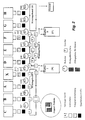
- FIGS. 1 and 2 show a schematic representation - each for itself - an embodiment a device according to the invention for the production of ready-to-cast Masks or core packages, with one of the number required for packaging different cores corresponding number of core shooters 1, which in are individually marked with the letters A-H. Furthermore are each three assembly tapes 2, 3, 4 are provided.
- the device has the core shooters 1, 5 assigned removal stations 6, also assigned to the core shooters 1, 5 Deburring devices 7 and correspondingly assigned quality controls 8 on. Furthermore, the core shooters 1, 5 are robots 9 and these again assigned to gripper 10.
- the assembly tapes 2, 3 and 4 closed support groups.
- the assembly tapes 2, 3 and 4 point for storing the cores or for serving pallets 11 on the double pallets are executed. More specifically, the pallets 11 include one for packaging of the cores serving package station 12 and one for storing a separate one Kerns serving storage space 13.
- the figures further show that the assembly lines 2, 3 and 4 at the transfer stations 14 material buffers 16 are assigned, can be stored in the replacement cores and from which replacement cores can be removed for feeding to the packaging process.
- KSM work flow of the device shown schematically in FIG. 1 is shown in the table below, the core shooters being abbreviated with the letter group KSM.
- Workflow Abl .: Filing Pak .: Paktieren maintenance KSM X RX KSM F RF Others comment KSM A KSM A Pak. A KSM F Pak. F RA> out of service 1 TOOL KSM B KSM B OJ B KSM F Pak. F RB> Pak. B 1 TOOL KSM C KSM C OJ C. KSM F Pak. F RC> Pak. C. 1 TOOL KSM D KSM D Pak. D KSM F Pak. F RD> out of service 1 TOOL KSM E KSM E OJ E KSM F Pak.
- the additional machine takes over X shooting the core A by the robot RX on the first Assembly line is deposited or packaged there.
- the core shooter F shoots the core F, which is packaged accordingly by the robot RF.
- Robot RA is out of order.
- core B is replaced by the additional machine X shot and placed on the first assembly line using the RX robot.
- Core shooter F still produces core F, with robots RX for Storage of the core and robot RB for packaging the core - on the one already stored Core A - serve.
- the auxiliary machine X shoots the Core C, which is deposited on the first assembly line by the RX robot.
- Core shooter F still shoots core F, using robot RC for packaging of the core C serves, etc.
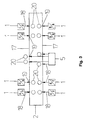
- FIG 3 shows a further exemplary embodiment of a device according to the invention for the production of cast-ready brands or core packages, where the assembly line 2 is designed in the sense of a closed support group.
- This funding group is through two mutually parallel, interconnected conveyor lines 17 formed.
- the two conveyor lines 17 run on the same level, wherein this arrangement of the schematic representation cannot be seen.
- the core shooters 1 are arranged on both sides of the two conveyor lines 17, with a symmetrical arrangement in the embodiment chosen here is present.
- Fig. 3 also reveals that the core shooters 1 in groups of each two core shooters 1 are combined locally.
- the core shooters 1 and the additional machine 5 are arranged outside the conveyor circuit, the cores from the core shooters 1 and the auxiliary machine 5 via a conveyor device, not shown, or via manipulators 18 to the respective Storage stations 19 are spent.
- the auxiliary machine 5 is arranged approximately centrally on the assembly line. As previously mentioned, those removed from the auxiliary machine 5 Cores by means of the manipulator 18 to the predetermined storage stations 19 spent, namely there on pallets of the assembly line 2, not shown in FIG. 3 filed.
- Fig. 3 further shows that the manipulator 18 both immediately the assembly line 2 or on the pallets present there as well as on the assembly line 2 away on the opposite part of the assembly line 2 or the opposite conveyor section 17 and thus on pallets present there Cores can.
- the cores are seen in the conveying direction of the assembly line 2 before or after a core shooter 1 or a group of core shooters 1 in the respective storage station 19 on the assembly line 2 or on the Pallets can be stored.
- two core shooters each form a group of core shooters are summarized.
Landscapes
- Engineering & Computer Science (AREA)
- Mechanical Engineering (AREA)
- Automatic Assembly (AREA)
- Containers And Plastic Fillers For Packaging (AREA)
- Cereal-Derived Products (AREA)
Description
| Benötigte Kernpakete pro Jahr | 400.000 |
| Anzahl der Wochen pro Jahr | 48 |
| Anzahl der Schichten pro Tag | 3 |
| Anzahl der Maschinen | 8 |
| Taktzeit der Maschine | 45 s |
| Garantierte Verfügbarkeit | 85% |
| Anzahl der Arbeitstage pro Woche | 6 |
| Anzahl der Arbeitsstunden pro Tag | 23 |
| d.h.: 48 x 6 x 23 = 6.624 h/Jahr |
| Gesamtstillstand pro Tag (⊘) [Woche] | 7,23 h [50,7 h] |
| Ausfallzeit: 2,95 h [20,7 h] | 23 h x (1-0,85%) = 3,45 h x 6 = 20,7 / 7 = 2,95 h |
| Wartungszeit: 4,28 h [30 h] | 24 h + 6 x (24 h - 23 h ) = 30 h / 7 = 4,28 h |

| Anzahl der Maschinen | 8+1 |
| Taktzeit der Maschine | 45 s |
| Garantierte Verfügbarkeit | 85% |
| Anzahl der Arbeitstage pro Woche | 7 |
| Anzahl der Arbeitsstunden pro Tag | 24 |
| d.h.: 48 x 7 x 24 = 8.064 h/Jahr |
Eff.Prod.std. bei der konventionellen Planung: 24 h - 7,23 h = 16,77 h / Tag und MC
16,77 h x 8 MC / 9 MC = 14,9 x 7 = 104,34 h
| Gesamtstillstandzeit pro Tag (0) [Woche] | 9,1 h [63,7 h] | 24 - 14,9 = 9,1 x 7 = 63,7 h |
| Ausfallzeit | 2,63 h [18,4 h] | (14,9 / 85%) - 14,9 = 2,63 x 7 = 18,4 h |
| Wartungszeit | 6,47 h [45,29 h] | 9,1 h - 2,63 h = 6,47 x 7 = 45,29 h |
| Konzept 2000: | Konventionell: | Änderung | |
| Maschinen-Investition | 9 X ..... | 8 X ..... | + 12,50% |
| Arbeitstunden pro Jahr | 8064 | 6624 | + 21,74% |
| Maximale Anzahl der Kernpakete pro Jahr | 645.120 | 529.920 | + 21,74% |
| Kapazitätsreserve [basierend auf 400.000] | 61,28% | 32,48% | + 88,66% |
| Wartungszeit pro Woche | 45,29 h | 30 h | + 50,96% |
| Wartungszeit pro Tag | 6,47 h | 1 h | + 547% |
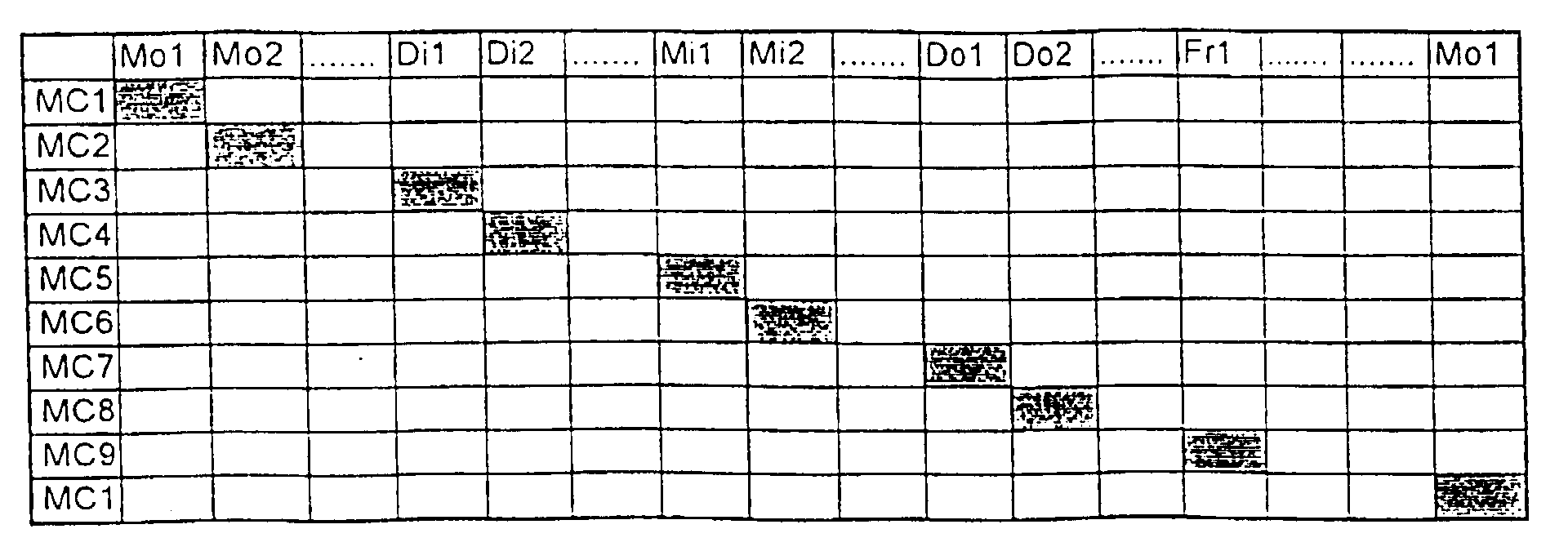
- Durch Teilung des Montagebandes ist es möglich, Teilpakete zu fertigen.
- Geht man von einer Gesamtwartung von 6 Stunden pro Maschine und Woche aus, benötigt man bei konventioneller Planung sechs Wartungsteams (zwei Wartungsteams pro Schicht), um innerhalb eines Tages die Wartung, Reinigung und Instandhaltung durchzuführen. Da das Wartungsteam nur an einem Tag ausgelastet ist, ist es notwendig, einen Teil dieser Aufgaben extern zu vergeben.


- Fig. 1
- in einer schematischen Darstellung eine erste Anordnung einer erfindungsgemäßen Vorrichtung zur Herstellung gießfertiger Kernpakete, wobei dort insgesamt drei Montagebänder vorgesehen sind,
- Fig. 2
- in einer schematischen Darstellung ein zweites Ausführungsbeispiel einer erfindungsgemäßen Vorrichtung zur Herstellung gießfertiger Kernpakete, wobei dort ebenfalls drei Montagebänder angeordnet sind und wobei das mittlere Montageband in etwa mäanderförmig verläuft und
- Fig. 3
- in einer schematischen Darstellung ein drittes Ausführungsbeispiel einer erfindungsgemäßen Vorrichtung zur Herstellung gießfertiger Kernpakete, wobei dort ein einziges Montageband mit geschlossenem Förderkreis und zwei gegenüberliegenden Förderstrecken sowie einer zentral angeordneten Zusatzmaschine vorgesehen ist.
| Arbeitsablauf: Abl.: Ablegen Pak.: Paktieren | ||||||
| Wartung | KSM X | RX | KSM F | RF | Sonstiges | Bemerkung |
| KSM A | KSM A | Pak. A | KSM F | Pak. F | RA>Außerbetrieb | 1 WZW |
| KSM B | KSM B | Abl. B | KSM F | Pak. F | RB>Pak. B | 1 WZW |
| KSM C | KSM C | Abl. C | KSM F | Pak. F | RC>Pak. C | 1 WZW |
| KSM D | KSM D | Pak. D | KSM F | Pak. F | RD>Außerbetrieb | 1 WZW |
| KSM E | KSM E | Abl. E | KSM F | Pak. F | RE>Pak. E | 1 WZW |
| KSM F | KSM F | Abl. F | - | - | RF>Pak. F | 1 WZW |
| KSM G | KSM F | Abl. F | KSM G | Abl. G | RF> Pak. F & RG>Pak. G | 2 WZW |
| KSM H | KSM F | Abl. F | KSM H | Abl. H | RF>Pak. F & RH>Pak. H | 2 WZW |
| Arbeitsablauf: Abl.: Ablegen Pak. Paktieren | ||||||
| Wartung | KSM X | RX | KSM F | RF | Sonstiges | Bemerkung |
| KSM A | KSM A | Pak. A | KSM F | Pak. F bei 5 | - | 1 WZW |
| KSM B | KSM B | Abl. B | KSM F | Pak. F bei 5 | RB>Pak. B | 1 WZW |
| KSM C | KSM C | Abl. C | KSM F | Pak. F bei 5 | RC>Pak. C | 1 WZW |
| KSM D | KSM D | Pak. D bei 2 | KSM F | Pak. F bei 5 | - | 1 WZW |
| KSM E | KSM E | Pak. E bei 8 | KSM F | Pak. F bei 11 | - | 1 WZW |
| KSM F | KSM F | Pak. F bei 8 | - | - | - | 1 WZW |
| KSM G | KSM F | Pak. F bei 8 | KSM G | Pak. G | - | 2 WZW |
| KSM H | KSM F | Pak. F bei 8 | KSM H | Abl. H | RH>Pak. H | 2 WZW |
Claims (21)
- Vorrichtung zur Herstellung gießfertiger Masken oder Kernpakete, mit einer der Anzahl der zur Paketierung erforderlichen unterschiedlichen Kerne entsprechenden Anzahl an Kernschießmaschinen (1) und einem Montageband (2), wobei die geschossenen und verfestigten Kerne aus den Kernschießmaschinen (1) entnommen, ggf. bearbeitet und auf dem Montageband (2) zu dem Kernpaket komplettiert werden,
dadurch gekennzeichnet, daß die Vorrichtung mindestens eine als zusätzliche Kernschießmaschine dienende Zusatzmaschine (5) zur ersatzweisen Fertigung eines jeden der zur Paketierung erforderlichen Kerne enthält, die einem Montageband (2) der Vorrichtung oder einem weiteren Montageband , das mit dem Montageband (2) kommuniziert, zugeordnet ist. - Vorrichtung nach Anspruch 1, dadurch gekennzeichnet, daß die Zusatzmaschine (5) ortsfest angeordnet ist.
- Vorrichtung nach Anspruch 1 oder 2, dadurch gekennzeichnet, daß die Zusatzmaschine (5) unmittelbar dem Montageband (2) zugeordnet ist und ggf. in Förderrichtung der Kerne gesehen vor der ersten oder nach der letzten regulären Kernschießmaschine (1) angeordnet ist.
- Vorrichtung nach Anspruch 1 oder 2, dadurch gekennzeichnet, daß die Zusatzmaschine (5) einem weiteren Montageband - Zusatzband - zugeordnet ist, welches mit dem ersten Montageband (2) kommuniziert, wobei das Montageband (2) zumindest im weitesten Sinne linear angeordnet sein kann und das Zusatzband ggf. im wesentlichen parallel zu dem Montageband verläuft, so daß das Montageband (2) mit Kernen beschickende Roboter (9) bzw. Manipulatoren auch das Zusatzband beschicken und von diesem Kerne entnehmen können.
- Vorrichtung nach einem der Ansprüche 1 bis 4, dadurch gekennzeichnet, daß die Zusatzmaschine (5), vorzugsweise aus einem Werkzeuglager heraus, mittels eines Roboters (9) bzw. Manipulators und/oder einer Fördereinrichtung mit Werkzeugen zur wahlweisen Herstellung eines jeden der zur Paketierung erforderlichen Kerne bestückbar ist.
- Vorrichtung nach einem der Ansprüche 1 bis 5, dadurch gekennzeichnet, daß das Montageband (2) derart angeordnet und ausgebildet ist, daß dort abgelegte bzw. paketierte Kerne mindestens zweimal den Bereich der Kernschießmaschinen (1) passieren.
- Vorrichtung nach einem der Ansprüche 1 bis 6, dadurch gekennzeichnet, daß das Montageband (2) einen die Kernschießmaschinen (1) passierenden offenen oder geschlossenen Förderkreis bildet, der vorzugsweise durch zwei in etwa parallele zueinander verlaufende, miteinander verbundene Förderstrecken (17) gebildet ist, die vorzugsweise zumindest weitgehend auf derselben Ebene verlaufen, wobei die Kernschießmaschinen (1) beidseits der Förderstrecken (17), vorzugsweise symmetrisch, angeordnet sein können und vorzugsweise in Gruppen zu je zwei Kernschießmaschinen (1) örtlich zusammengefaßt sind.
- Vorrichtung nach Anspruch 7, dadurch gekennzeichnet, daß die Kernschießmaschinen (1), insbesondere auch die Zusatzmaschine (5), außerhalb oder innerhalh des Förderkreises angeordnet sind bzw. ist.
- Vorrichtung nach Anspruch 7 oder 8, dadurch gekennzeichnet, daß die von der Zusatzmaschine (5) entnommenen Kerne mittels eines Manipulators (18) an beliebigen Stellen des Förderkreises, vorzugsweise an vorgebbaren Ablagestationen (19), auf dem Montageband (2) bzw. auf den Paletten ablegbar sind, wobei der Manipulator (18) unmittelbar auf das Montageband (2) bzw. auf dort vorliegende Paletten und auch über das Montageband (2) hinweg auf dem gegenüberliegenden Teil bzw. auf der gegenüberliegenden Förderstrecke (17) des Montagebandes (2) Kerne ablegen kann.
- Vorrichtung nach einem der Ansprüche 7 bis 9, dadurch gekennzeichnet, daß die Keme in Förderrichtung des Montagebandes (2) gesehen vor oder nach einer Kernschießmaschine (1) oder einer Gruppe von Kernschießmaschinen (1), in der jeweiligen Ablagestation (19), auf das Montageband (2) bzw. die Palette ablegbar sind.
- Vorrichtung nach einem der Ansprüche 1 bis 6, dadurch gekennzeichnet, daß das Montageband (2) in etwa mäanderförmig verläuft und dabei den Bereich der Kernschießmaschinen (1) mindestens zweimal passiert.
- Vorrichtung nach einem der Ansprüche 1 bis 11, wobei das Montageband (2) zur Ablage der Keme bzw. zur Paketierung dienende Paletten (11) trägt, dadurch gekennzeichnet, daß die Palette (11) einen Bereich zur Paketierung der Kerne - Paketierplatz (12) - und einen Bereich zur Ablage eines Kems - Ablageplatz (13) - aufweist, wobei der Ablageplatz (13) zur Aufnahme eines beliebigen Kerns und zum anschließenden Zuführen des abgelegten Kerns in den Vorgang der Paketierung - in der richtigen Reihenfolge - dient, und wobei die Palette (11) vorzugsweise in die beiden Bereiche geteilt ist und daß die beiden Bereiche der Palette (11) ggf. unabhängig voneinander handhabbar und miteinander verbindbar sind.
- Vorrichtung nach einem der Ansprüche 1 bis 12, dadurch gekennzeichnet, daß mindestens zwei Gruppen von Kernschießmaschinen (1) über entsprechende Montagebänder (2, 3, 4) aneinandergereiht sind und daß im Bereich zwischen oder an den Montagebändern (2, 3, 4) Übergabestationen (14) mit zur Übergabe dienenden Manipulatoren vorgesehen sind, wobei die Zusatzmaschine (5) unmittelbar an oder nahe der Übergabestation (14) angeordnet und dabei der Gruppe der jeweils vorangegangenen oder der jeweils nachfolgenden Kernschießmaschinen (1) zugeordnet sein kann und wobei in der Reihenfolge der Paketierung die jeweils letzte Kernschießmaschine (1) einer jeweils vorangegangenen Gruppe als Zusatzmaschine (5) zum Fertigen eines Kerns einer beliebigen anderen Kernschießmaschine (1) umrüstbar und zum Schießen von Kernen der Kernschießmaschinen (1) der folgenden Gruppe einsetzbar ist oder wobei in der Reihenfolge der Paketierung die jeweils erste Kernschießmaschine (1) einer jeweils nachfolgenden Gruppe als Zusatzmaschine (5) zum Fertigen eines Kems einer beliebigen anderen Kernschießmaschine (1) umrüstbar und zum Schießen von Kernen der Kernschießmaschinen (1) der jeweils vorangegangenen Gruppe einsetzbar ist.
- Vorrichtung nach Anspruch 13, dadurch gekennzeichnet, daß innerhalb jeder Gruppe von Kernschießmaschinen (1) jede der Kernschießmaschinen (1) als reguläre Kernschießmaschine (1) oder als Zusatzmaschine (5) zum Fertigen eines Kerns einer beliebigen anderen Kernschießmaschine (1) umrüstbar und entsprechend einsetzbar ist, wobei in funktionaler Hinsicht zwischen den Gruppen von Kernschießmaschinen (1), d.h. zwischen den Montagebändern (2, 3, 4), Lager zum Ein- und Ausschleusen einzelner Kerne und/oder bereits paketierter oder zumindest teilpaketierter Kernpakete vorgesehen sein können.
- Vorrichtung nach einem der Ansprüche 1 bis 14, dadurch gekennzeichnet, daß den Kernschießmaschinen (1) nach der Entnahmestation (6) im Bereich vor dem Montageband (2) jeweils eine Entgratungsvorrichtung (7) nachgeordnet ist.
- Vorrichtung nach einem der Ansprüche 1 bis 15, dadurch gekennzeichnet, daß den Kernschießmaschinen nach der Entnahmestation (6), vorzugsweise nach der Entgratungsvorrichtung (7), vor dem Montageband (2) jeweils eine Station zur Qualitätskontrolle (8) nachgeordnet ist.
- Vorrichtung nach einem der Ansprüche 1 bis 16, dadurch gekennzeichnet, daß vorzugsweise jeder Kernschießmaschine (1) ein Roboter (9) bzw. Manipulator mit mindestens einem Greifer (10) zugeordnet ist, wobei der Roboter (9) zur Entnahmestation (6), weiteren Handhabung und zur Paketierung oder Ablage der jeweils geschossenen Kerne dient.
- Vorrichtung nach einem der Ansprüche 1 bis 17, dadurch gekennzeichnet, daß die Kernschießmaschinen (1) jeweils mit zwei unabhängig voneinander arbeitenden Schußköpfen mit separater Druckluft- und Sandversorgung ausgestattet sind, wobei die zu einer Gruppe zusammengefaßten, nebeneinander angeordneten Kernschießmaschinen (1), vorzugsweise paarweise, zum Schießen dergleichen Kerntypen dienen können.
- Vorrichtung nach einem der Ansprüche 1 bis 18, dadurch gekennzeichnet, daß an den Ablagestationen (19) der Zusatzmaschine (5) Kameras (20) zur Überwachung der Paletten bzw. der Paketierungssituation vorgesehen sind.
- Vorrichtung nach einem der Ansprüche 1 bis 19, dadurch gekennzeichnet, daß an den Ablagestationen (19) sämtlicher Kernschießmaschinen (1) Kameras (20) zur Überwachung der Paletten bzw. der Paketierungssituation auf den Paletten vorgesehen sind.
- Verfahren zur Herstellung gießfertiger Masken oder Kern pakete, wobei an mindestens zwei Kernschießmaschinen Kerne aus Formstoff geschossen und verfestigt, aus den Kernschießmaschinen entnommen, ggf. bearbeitet und gemeinsam zu einem Kernpaket komplettiert werden und wobei die Kernschießmaschinen über ein Montageband gekoppelt sind, insbesondere zur Anwendung einer Vorrichtung nach einem der Ansprüche 1 bis 20,
dadurch gekennzeichnet, daß im Falle des Ausfalls oder der Wartung einer der Kernschießmaschinen ein jeder der zur Paketierung erfordeflichen Keme über mindestens eine als zusätzliche Kemschießmaschine dienende Zusatzmaschine ersatzweise geschossen werden kann.
Applications Claiming Priority (5)
| Application Number | Priority Date | Filing Date | Title |
|---|---|---|---|
| DE19645448 | 1996-11-04 | ||
| DE19645448 | 1996-11-04 | ||
| DE19725379 | 1997-06-16 | ||
| DE19725379A DE19725379C2 (de) | 1996-11-04 | 1997-06-16 | Vorrichtung und Verfahren zur Herstellung gießfertiger Masken oder Kernpakete |
| PCT/DE1997/001911 WO1998019810A1 (de) | 1996-11-04 | 1997-09-01 | Vorrichtung und verfahren zur herstellung giessfertiger masken oder kernpakete |
Publications (2)
| Publication Number | Publication Date |
|---|---|
| EP0951370A1 EP0951370A1 (de) | 1999-10-27 |
| EP0951370B1 true EP0951370B1 (de) | 2001-02-07 |
Family
ID=26030966
Family Applications (1)
| Application Number | Title | Priority Date | Filing Date |
|---|---|---|---|
| EP97942765A Expired - Lifetime EP0951370B1 (de) | 1996-11-04 | 1997-09-01 | Vorrichtung und verfahren zur herstellung giessfertiger masken oder kernpakete |
Country Status (5)
| Country | Link |
|---|---|
| US (1) | US6422296B1 (de) |
| EP (1) | EP0951370B1 (de) |
| CA (1) | CA2270612A1 (de) |
| ES (1) | ES2155701T3 (de) |
| WO (1) | WO1998019810A1 (de) |
Families Citing this family (2)
| Publication number | Priority date | Publication date | Assignee | Title |
|---|---|---|---|---|
| US8220523B2 (en) | 2010-09-16 | 2012-07-17 | Anderson & Associates | Method and apparatus for manipulating investment casting mold handlers |
| US11103918B2 (en) | 2018-03-19 | 2021-08-31 | Honda Motor Co., Ltd. | Core blowing apparatus for robotic system |
Family Cites Families (11)
| Publication number | Priority date | Publication date | Assignee | Title |
|---|---|---|---|---|
| US4100961A (en) * | 1976-11-18 | 1978-07-18 | Acme-Cleveland Corporation | Foundry molding machine |
| US4757855A (en) * | 1987-04-02 | 1988-07-19 | Roberts Corporation | Method and apparatus for loading and unloading tooling from a foundry machine |
| FR2643579B1 (fr) * | 1989-02-24 | 1993-12-31 | Kuhn Sa | Machine a tirer des noyaux de fonderie |
| DE4033887C2 (de) * | 1990-10-25 | 1994-07-28 | Hottinger Adolf Masch | Vorrichtung und Verfahren zur Herstellung von Formteilen für Gießereizwecke |
| DE4341122C2 (de) | 1993-06-02 | 1995-04-06 | Hottinger Adolf Masch | Vorrichtung und Verfahren zur Herstellung gießfertiger Masken bzw. Kernpakete |
| DE4318259C1 (de) * | 1993-06-02 | 1994-02-17 | Hottinger Adolf Masch | Vorrichtung und Verfahren zur Herstellung gießfertiger Masken bzw. Kernpakete |
| DE4322986C1 (de) * | 1993-07-09 | 1994-07-07 | Hottinger Adolf Masch | Vorrichtung und Verfahren zur Schußhaubenreinigung bei der Herstellung gießfertiger Masken bzw. Kernpakete |
| EP0731741B1 (de) * | 1993-12-03 | 1997-07-16 | Adolf Hottinger Maschinenbau GmbH | Vorrichtung und verfahren zur herstellung giessfertiger masken bzw. kernpakete |
| DK174296B1 (da) * | 1994-11-18 | 2002-11-25 | Dansk Ind Syndikat | Fremgangsmåde ved drift af forme- og støbeanlæg, samt anlæg til brug ved fremgangsmådens udøvelse |
| DE19534984C1 (de) * | 1995-09-20 | 1996-08-14 | Adolf Hottinger Kg | Verfahren zur Qualitätskontrolle in Kern- oder Maskenschießmaschinen und Vorrichtung zum Kern- oder Maskenschießen |
| DE19535337C2 (de) * | 1995-09-22 | 1999-05-20 | Adolf Hottinger Kg | Verfahren zur Qualitätskontrolle bei der Herstellung gießfertiger Masken oder Kernpakete |
-
1997
- 1997-09-01 WO PCT/DE1997/001911 patent/WO1998019810A1/de not_active Ceased
- 1997-09-01 US US09/297,629 patent/US6422296B1/en not_active Expired - Fee Related
- 1997-09-01 CA CA002270612A patent/CA2270612A1/en not_active Abandoned
- 1997-09-01 EP EP97942765A patent/EP0951370B1/de not_active Expired - Lifetime
- 1997-09-01 ES ES97942765T patent/ES2155701T3/es not_active Expired - Lifetime
Also Published As
| Publication number | Publication date |
|---|---|
| CA2270612A1 (en) | 1998-05-14 |
| US6422296B1 (en) | 2002-07-23 |
| EP0951370A1 (de) | 1999-10-27 |
| ES2155701T3 (es) | 2001-05-16 |
| WO1998019810A1 (de) | 1998-05-14 |
Similar Documents
| Publication | Publication Date | Title |
|---|---|---|
| DE102004053503B4 (de) | Honanlage mit mehreren Arbeitsstationen | |
| EP2822883B1 (de) | Anlage und verfahren zum bearbeiten optischer linsen | |
| DE3409843C2 (de) | Verfahren und Anlage zum Herstellen von aus mehreren Teilen bestehenden Werkstücken | |
| DE3540316A1 (de) | Fertigungsanlage zur automatischen montage und pruefung elektronischer flachbaugruppen | |
| DE102015015040A1 (de) | Verfahren, Anlage und System zur Bearbeitung optischer Linsen | |
| DE19948139A1 (de) | Flexibles Fertigungssystem | |
| EP1125684A2 (de) | Verkettetes Fertigungssystem und Automationszelle dafür | |
| DE102009026043A1 (de) | Vorrichtung und Verfahren zum Beschicken einer Weiterverarbeitungseinheit mit Artikeln | |
| DE60226073T2 (de) | Zusammensetzungsverarbeitungssystem für die blechverarbeitung | |
| DE10232402A1 (de) | Puffersystem | |
| EP1270114B1 (de) | Niederdruck-Kokillengiessanlage und Kokille dafür | |
| DE102016007837A1 (de) | Verfahren und System zur Bearbeitung optischer Linsen | |
| DE3902063C2 (de) | ||
| DE102017220176A1 (de) | Verfahren zum Betreiben einer Montagelinie, Steuerungssystem und Montagelinie | |
| DE19725379C2 (de) | Vorrichtung und Verfahren zur Herstellung gießfertiger Masken oder Kernpakete | |
| EP0951370A1 (de) | Vorrichtung und verfahren zur herstellung giessfertiger masken oder kernpakete | |
| DE10140447C2 (de) | Streckblasmaschine und Verfahren zur Herstellung von Behältern mit der Streckblasmaschine | |
| DE3942492A1 (de) | Palettiervorrichtung fuer spulen | |
| DE4315133B4 (de) | Einrichtung bei Buntaufteilanlagen | |
| DE3333993C2 (de) | Montageverfahren | |
| DE102020213540A1 (de) | Fertigungsanlage zur Serienfertigung von Kraftfahrzeugen und Verfahren zum Fertigen eines Kraftfahrzeugs | |
| DE10342677B4 (de) | Entkopplungs- und Synchronisationsmodul | |
| DE3706122A1 (de) | Verfahren und anlage zur handhabung von werkstuecken und zu deren bearbeitung benoetigten werkzeugen an werkzeugmaschinen | |
| DE102015101973B4 (de) | Verfahren und Vorrichtung zur Herstellung von Solarzellsträngen | |
| EP0731741B1 (de) | Vorrichtung und verfahren zur herstellung giessfertiger masken bzw. kernpakete |
Legal Events
| Date | Code | Title | Description |
|---|---|---|---|
| PUAI | Public reference made under article 153(3) epc to a published international application that has entered the european phase |
Free format text: ORIGINAL CODE: 0009012 |
|
| 17P | Request for examination filed |
Effective date: 19990520 |
|
| AK | Designated contracting states |
Kind code of ref document: A1 Designated state(s): CH DE ES FR GB IT LI |
|
| GRAG | Despatch of communication of intention to grant |
Free format text: ORIGINAL CODE: EPIDOS AGRA |
|
| 17Q | First examination report despatched |
Effective date: 20000302 |
|
| GRAG | Despatch of communication of intention to grant |
Free format text: ORIGINAL CODE: EPIDOS AGRA |
|
| GRAH | Despatch of communication of intention to grant a patent |
Free format text: ORIGINAL CODE: EPIDOS IGRA |
|
| GRAH | Despatch of communication of intention to grant a patent |
Free format text: ORIGINAL CODE: EPIDOS IGRA |
|
| GRAA | (expected) grant |
Free format text: ORIGINAL CODE: 0009210 |
|
| AK | Designated contracting states |
Kind code of ref document: B1 Designated state(s): CH DE ES FR GB IT LI |
|
| REG | Reference to a national code |
Ref country code: CH Ref legal event code: EP |
|
| ITF | It: translation for a ep patent filed | ||
| REF | Corresponds to: |
Ref document number: 59702991 Country of ref document: DE Date of ref document: 20010315 |
|
| REG | Reference to a national code |
Ref country code: ES Ref legal event code: FG2A Ref document number: 2155701 Country of ref document: ES Kind code of ref document: T3 |
|
| GBT | Gb: translation of ep patent filed (gb section 77(6)(a)/1977) |
Effective date: 20010427 |
|
| ET | Fr: translation filed | ||
| PLBE | No opposition filed within time limit |
Free format text: ORIGINAL CODE: 0009261 |
|
| STAA | Information on the status of an ep patent application or granted ep patent |
Free format text: STATUS: NO OPPOSITION FILED WITHIN TIME LIMIT |
|
| REG | Reference to a national code |
Ref country code: GB Ref legal event code: IF02 |
|
| 26N | No opposition filed | ||
| PGFP | Annual fee paid to national office [announced via postgrant information from national office to epo] |
Ref country code: FR Payment date: 20020916 Year of fee payment: 6 |
|
| PGFP | Annual fee paid to national office [announced via postgrant information from national office to epo] |
Ref country code: CH Payment date: 20020920 Year of fee payment: 6 |
|
| PGFP | Annual fee paid to national office [announced via postgrant information from national office to epo] |
Ref country code: GB Payment date: 20030821 Year of fee payment: 7 |
|
| PG25 | Lapsed in a contracting state [announced via postgrant information from national office to epo] |
Ref country code: LI Free format text: LAPSE BECAUSE OF NON-PAYMENT OF DUE FEES Effective date: 20030930 Ref country code: CH Free format text: LAPSE BECAUSE OF NON-PAYMENT OF DUE FEES Effective date: 20030930 |
|
| REG | Reference to a national code |
Ref country code: CH Ref legal event code: PL |
|
| PG25 | Lapsed in a contracting state [announced via postgrant information from national office to epo] |
Ref country code: FR Free format text: LAPSE BECAUSE OF NON-PAYMENT OF DUE FEES Effective date: 20040528 |
|
| REG | Reference to a national code |
Ref country code: FR Ref legal event code: ST |
|
| PG25 | Lapsed in a contracting state [announced via postgrant information from national office to epo] |
Ref country code: GB Free format text: LAPSE BECAUSE OF NON-PAYMENT OF DUE FEES Effective date: 20040901 |
|
| GBPC | Gb: european patent ceased through non-payment of renewal fee |
Effective date: 20040901 |
|
| PGFP | Annual fee paid to national office [announced via postgrant information from national office to epo] |
Ref country code: ES Payment date: 20080923 Year of fee payment: 12 |
|
| PGFP | Annual fee paid to national office [announced via postgrant information from national office to epo] |
Ref country code: IT Payment date: 20080925 Year of fee payment: 12 |
|
| PGFP | Annual fee paid to national office [announced via postgrant information from national office to epo] |
Ref country code: DE Payment date: 20080722 Year of fee payment: 12 |
|
| PG25 | Lapsed in a contracting state [announced via postgrant information from national office to epo] |
Ref country code: DE Free format text: LAPSE BECAUSE OF NON-PAYMENT OF DUE FEES Effective date: 20100401 |
|
| PG25 | Lapsed in a contracting state [announced via postgrant information from national office to epo] |
Ref country code: IT Free format text: LAPSE BECAUSE OF NON-PAYMENT OF DUE FEES Effective date: 20090901 |
|
| REG | Reference to a national code |
Ref country code: ES Ref legal event code: FD2A Effective date: 20110718 |
|
| PG25 | Lapsed in a contracting state [announced via postgrant information from national office to epo] |
Ref country code: ES Free format text: LAPSE BECAUSE OF NON-PAYMENT OF DUE FEES Effective date: 20110706 |
|
| PG25 | Lapsed in a contracting state [announced via postgrant information from national office to epo] |
Ref country code: ES Free format text: LAPSE BECAUSE OF NON-PAYMENT OF DUE FEES Effective date: 20090902 |