EP0951112A2 - Source à laser accordable avec variation coninue et à large bande de la longueur d'onde d'oscillation - Google Patents
Source à laser accordable avec variation coninue et à large bande de la longueur d'onde d'oscillation Download PDFInfo
- Publication number
- EP0951112A2 EP0951112A2 EP99106650A EP99106650A EP0951112A2 EP 0951112 A2 EP0951112 A2 EP 0951112A2 EP 99106650 A EP99106650 A EP 99106650A EP 99106650 A EP99106650 A EP 99106650A EP 0951112 A2 EP0951112 A2 EP 0951112A2
- Authority
- EP
- European Patent Office
- Prior art keywords
- laser
- semiconductor laser
- wavelength
- diffraction grating
- diffraction
- Prior art date
- Legal status (The legal status is an assumption and is not a legal conclusion. Google has not performed a legal analysis and makes no representation as to the accuracy of the status listed.)
- Granted
Links
Images


Classifications
-
- H—ELECTRICITY
- H01—ELECTRIC ELEMENTS
- H01S—DEVICES USING THE PROCESS OF LIGHT AMPLIFICATION BY STIMULATED EMISSION OF RADIATION [LASER] TO AMPLIFY OR GENERATE LIGHT; DEVICES USING STIMULATED EMISSION OF ELECTROMAGNETIC RADIATION IN WAVE RANGES OTHER THAN OPTICAL
- H01S5/00—Semiconductor lasers
- H01S5/10—Construction or shape of the optical resonator, e.g. extended or external cavity, coupled cavities, bent-guide, varying width, thickness or composition of the active region
- H01S5/14—External cavity lasers
- H01S5/141—External cavity lasers using a wavelength selective device, e.g. a grating or etalon
- H01S5/143—Littman-Metcalf configuration, e.g. laser - grating - mirror
Definitions
- the present invention relates to a laser source apparatus capable of continuously changing the oscillation wavelength, which is used in the fields of optical communications and precision measurement and, more particularly, to a tunable laser source apparatus which can continuously sweep the oscillation wavelength in a wideband by using an optical amplification element, e.g., a semiconductor laser (to be referred to as an LD hereinafter), in a wide wavelength range.
- an optical amplification element e.g., a semiconductor laser (to be referred to as an LD hereinafter), in a wide wavelength range.
- the frequency difference between beams that can be detected by a photodetector is electrically limited.
- the upper limit of this frequency difference is about 10 GHz.
- the frequency of the target beam must be tuned into a frequency within about 10 GHz.
- a laser source apparatus capable of continuously sweeping the oscillation wavelength near a desired wavelength is required.
- a tunable laser source apparatus called an external cavity laser
- an optical amplification element having a wide gain band e.g., a laser diode (LD)
- LD laser diode
- a wavelength selection element such as a diffraction grating disposed outside the optical amplification element, thereby causing laser oscillation within the wavelength range.
- a wavelength selection element that is used most widely is a diffraction grating.
- the wavelength to be selected is changed by changing the angle of the diffraction grating with respect to the incidence direction of light.
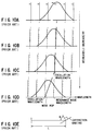
- FIG. 9A shows the arrangement of a typical external cavity laser using a diffraction grating.
- FIGS. 9B, 9C, 9D, and 9E show the principle of oscillation wavelength determination in the external cavity laser shown in FIG. 9A.
- this external cavity laser is comprised of an LD 11 having one end facet 11b covered with an AR (Anti-Reflection) coating, lenses 13a and 13b, and a diffraction grating 21 disposed on the end facet 11b side.
- AR Anti-Reflection
- the diffraction grating 21 can be rotated and translated.
- the diffraction grating 21 and the other end facet (without any AR coating) 11a of the LD 11 constitute an external cavity.
- the arrangement of the diffraction grating in which the wavelength of light received from the LD and directly diffracted toward the LD by the diffraction grating is used as a selected wavelength is called a Littrow mounting.
- the oscillation wavelength of an external cavity laser including a wavelength selection element is determined by two factors regardless of whether such a Littrow mounting is used.
- the first factor is the wavelength that satisfies a resonance condition determined by the optical length of the overall cavity that causes laser oscillation.
- L the optical length (to be referred to as the cavity length hereinafter) of the overall cavity
- ⁇ the frequency of input light
- P0 the power of input light
- P1 the power of output light
- each FSR includes a plurality of resonance frequencies at which the transmittance (output power P1/input power P0) becomes maximum.
- n th-order mode When a given resonance frequency is n times the FSR, this frequency is called the n th-order mode.
- a wavelength corresponding to a resonance frequency be called a resonance wavelength.
- Another factor that determines the oscillation wavelength of the external cavity laser is the gain distribution that is band-limited by the diffraction grating shown in FIG. 9D or a wavelength selection element in general.
- the gain in the selected wavelength range of the diffraction grating can be regarded as constant. For this reason, the band-limited gain distribution can be regarded as identical to the selected wavelength spectrum of the diffraction grating.
- a peak wavelength of a selected wavelength spectrum will therefore be simply referred to as a selected wavelength hereinafter.
- the external cavity laser starts oscillation in one of the above modes which is positioned at the frequency at which the highest gain can be obtained.
- the selected wavelength does not coincide with the oscillation wavelength.
- FIGS. 10A to 10E show a change in oscillation wavelength in a state wherein the oscillation wavelength differs in change rate from the selected wavelength.
- the oscillation wavelength in the current oscillation mode differs from the selected wavelength by about 1/2 the FSR at this time, the oscillation wavelength shifts from the current oscillation mode to an adjacent mode to make a shift from the state in FIG. 10C to the state in FIG. 10D. As a result, the oscillation wavelength discontinuously changes.
- This phenomenon is called a mode hop or mode jump.
- a mode hop must be prevented by synchronously changing the resonance wavelength at which oscillation is being caused and the selected wavelength, i.e., simultaneously changing them while appropriately maintaining the relationship between the cavity length and the angle of the diffraction grating in the external cavity laser based on the Littrow mounting.
- a technique based on one concept aims at realizing a mechanism of capable of simultaneously changing the resonance wavelength and the selected wavelength while maintaining their relationship with one controlled variable to prevent a mode hop.
- a technique based on the other concept aims at increasing the degree of freedom in control on the resonance wavelength and selected wavelength with a plurality of controlled variables.
- the angle of the diffraction grating and the resonance wavelength i.e., the cavity length, are independently changed on the basis of a combination of controlled variables obtained in advance in accordance with the oscillation wavelength.
- a laser medium, a lens, and the like are arranged, and they have wavelength dispersion characteristics, so the continuous wavelength sweep range is limited with the use of only the simple mechanism of keeping changes in the angle of the diffraction grating and cavity length at a predetermined ratio.
- the continuous wavelength sweep range is not limited by the wavelength dispersion characteristics of elements in the external cavity laser, it is not easy to sweep the oscillation wavelength in a wide band while matching the oscillation wavelength with the selected wavelength with high precision by only setting the cavity length and the angle of the diffraction grating to values obtained in advance in accordance with the oscillation wavelength.
- the oscillation wavelength can be continuously swept in a specific wavelength range, it is difficult to perform a continuous wavelength sweep throughout the entire oscillation band of the LD. In some cases, multi-mode oscillation occurs or no oscillation can be caused at a specific wavelength.
- the technique using a plurality of controlled variables performs wavelength sweeps, continuously relying on the mechanical precision at the initial adjustment and the parameters determined by experiment, and hence is susceptible to external disturbances, e.g., changes in cavity length and the like due to changes in ambient temperature.
- each of the mode hop prevention techniques described above is susceptible to slight plastic deformation of components due to a shock and the like and changes over time.
- wavelengths at which mode hops occur are checked while a movable portion supporting a diffraction grating or the like is moved to change the oscillation wavelength near a desired wavelength, and the laser is adjusted to increase the interval of the checked wavelengths, i.e., the continuous sweep range.
- the present invention has been made in consideration of the above situation, and has as its first object to provide a tunable laser source apparatus which includes an effective means for detecting the difference between the oscillation wavelength and the selected wavelength, which causes a mode hop, together with a sign, and can make systematic adjustment for the prevention of a mode hop independently of a trial-and-error method.
- a tunable laser source apparatus comprising:
- a tunable laser source apparatus including an external cavity having a semiconductor laser having at least one laser output end facet covered with an AR coating and diffraction means including a first reflector and a diffraction grating and having wavelength selectivity with which light emerging from the end facet of the semiconductor laser which is covered with the AR coating is received and light having a predetermined wavelength is selected and reflected toward the semiconductor laser, comprising:
- the first factor is that there has been no effective technique of detecting an observation indicating the difference between the oscillation wavelength and the selected wavelength, which causes a mod hop.
- each conventional mode hop prevention technique is a technique of performing control based on controlled variables obtained in advance in accordance with the oscillation wavelength. From another viewpoint, each conventional technique must be based on the concept of so-called open loop control. That is, control is entirely based on the initial settings.
- the apparatus uses a technique of detecting a change in the angle of the optical path of light fed back from the diffraction grating to the LD as an observation variable including information about the difference between the oscillation wavelength and the selected wavelength.
- the tunable laser source apparatus includes a semiconductor laser for oscillating laser light, a diffraction means for diffracting the laser light and feeding back laser light, of the diffracted laser light, which has a predetermined wavelength to the semiconductor laser, and an angle detection means for receiving part of the laser light fed back to the semiconductor laser and detecting the angle defined by the optical path of the laser light fed back to the semiconductor laser and the optical path of the laser light oscillated by the semiconductor laser.
- closed loop control for determining a controlled variable to be fed back based on the above observation variable is used.
- a tunable laser source apparatus including an external cavity having a semiconductor laser having at least one end facet (, from which laser light is emitted,) covered with an AR coating and a diffraction means including a first reflector and a diffraction grating and having wavelength selectivity with which light emerging from the end facet of the semiconductor laser which is covered with the AR coating is received and light having a predetermined wavelength is selected and reflected toward the semiconductor laser, comprising an angle detection means for detecting an angle defined by an optical path of the light emitted by the semiconductor laser and an optical path of the diffracted light reflected by the diffraction means, and a control section for controlling at least one of a cavity length of the external cavity and a wavelength selected by the diffraction means so as to set the angle detected by the angle detection means to zero.
- closed loop control has been widely used as the most standard engineering means but has not been used for the prevention of a mode hop for the following reasons.
- the former problem can be easily solved by detecting a change in the angle of light fed back from the diffraction grating as described later.
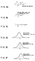
- FIGS. 3A to 3F are schematic views showing an external cavity laser based on the Littrow mounting and the diffraction direction of light having the oscillation wavelength.
- FIG. 3B shows a case wherein only the cavity length decreases while the angle of the diffraction grating does not change from that in the initial state.
- an oscillation wavelength ⁇ 1 becomes ⁇ 1 ⁇ ⁇ g in accordance with the cavity length.
- each angle of diffracted light in this specification means an angle within a projection plane on the drawing area, and any argument in a direction perpendicular to the drawing area can be neglected.
- an oscillation wavelength ⁇ 2 becomes ⁇ 2 > ⁇ g.
- the diffracted light travels in the direction expressed by ⁇ ⁇ 0.
- the angle ⁇ of the light traveling from the diffraction grating to the LD is almost proportional to a difference ⁇ g - ⁇ between the selected wavelength ⁇ g and the oscillation wavelength ⁇ .
- the cavity length is to be adjusted while the angle of the diffraction grating is fixed.
- the selected wavelength and the oscillation wavelength can be systematically and easily made to coincide with each other.
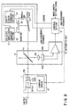
- FIG. 1 is a block diagram showing a tunable laser source apparatus according to the first embodiment of the present invention which corresponds to the first aspect described above.
- FIG. 2 is a block diagram showing a tunable laser source apparatus according to the second embodiment of the present invention which corresponds to the second aspect described above.
- a diffraction section 2 including a diffraction grating 21 and a first reflector 22, an optical amplification section 1, and a second reflector 3 constitute an external cavity laser.
- the optical amplification section 1 is comprised of an LD 11, a current source 12 for driving the LD 11, and lenses 13a and 13b.
- input/output end facets 11a and 11b of the LD 11 are covered with AR coatings.
- the diffraction grating 21 also serves as the first reflector 22.
- the diffraction section 2 includes a selected wavelength changing section 23 for rotating the diffraction grating 21 or the first reflector 22 in response to a control signal received from the control section 5, and a cavity length changing section 24 for translating the diffraction grating 21 and the first reflector 22.
- the above arrangement is the same as that of a conventional tunable laser source apparatus.
- the present invention includes the angle detection section 4 for outputting an angle detection signal by detecting the angle defined by the optical path of light traveling from the diffraction grating 21 to the LD 11 and the optical path of light traveling from the LD 11 to the diffraction grating 21.
- the angle detection signal detected by the angle detection section 4 is input, as an error signal for closed loop feedback control, to a control section 5.
- the control section 5 outputs a predetermined control signal to the current source 12, the selected wavelength changing section 23, and the cavity length changing section 24 on the basis of an externally input wavelength setting signal as in the prior art, and also outputs a feedback control signal corresponding to at least one of these control objects upon adding it to the predetermined control signal on the basis of the error signal detected by the angle detection section 4.
- the angle detection section 4 is comprised of a beam splitter 41, photodetectors 42a and 42b, and an arithmetic unit 43.
- the beam splitter 41 splits part of light traveling from the diffraction section 2 to the optical amplification section 1 and makes the extracted light strike the photodetectors 42a and 42b.
- These photodetectors 42a and 42b are arranged to respectively receive halves of light split by the beam splitter 41 when the angle defined by the optical path of light traveling from the diffraction grating 21 to the LD 11 and the optical path of light traveling from the LD 11 to the diffraction grating 21 is 0°.
- the arithmetic unit 43 outputs an angle detection signal in an amount corresponding to the angle defined by the optical path of light traveling from the optical amplification section 1 to the diffraction section 2 and the optical path of light traveling from the diffraction section 2 to the optical amplification section 1 on the basis of detection signals from the photodetectors 42a and 42b.
- the arithmetic unit 43 simply outputs the difference between the two light reception signals from the photodetectors 42a and 42b as an error signal.
- the cavity length may be changed by using a method of translating the second reflector 3, a method of changing the driving current supplied to the LD, a method of inserting a transparent medium in the external cavity to change the optical path length and changing the thickness or refractive index of the medium, or the like instead of placing the cavity length changing section 24 in the diffraction section 2 as in this case.
- the omission of the closed loop portion, which is used for feedback from the control section 5 to the diffraction section 2 on the basis of an error signal from the angle detection section 4, from the second embodiment amounts to the first embodiment shown in FIG. 1 as the embodiment according to the first aspect of the present invention described above.
- an error signal can be extracted as the above angle detection signal from the angle detection section 4.
- angle detection section 4 The operation of the angle detection section 4 will be described below with reference to FIGS. 4A to 4D.
- FIG. 4A schematically shows the arrangement of the angle detection section 4 and the positions of beams therein.
- FIG. 4B shows the positions of the light-receiving areas of the photodetectors 42a and 42b and beams and the relationship in magnitude between the wavelengths.
- the angle of the optical path of light traveling from the diffraction grating and the LD changes depending on the relationship in magnitude between a selected wavelength ⁇ g and an oscillation wavelength ⁇ .
- the beam splitter 41 and the photodetectors 42a and 42b are arranged in accordance with the positional relationship shown in FIG. 4A.
- the arithmetic unit 43 calculates the difference between two light reception signals to detect an argument.
- the photodetectors 42a and 42b may be arranged such that the power of light detected by the two photodetectors become equal to each other when the oscillation wavelength ⁇ coincides with the selected wavelength ⁇ g, i.e., the laser oscillates at a wavelength at which no mode hop easily occurs.
- the diameter of the beam may be adjusted by using an appropriate lens or the like.
- FIG. 4C shows detection signals from the photodetectors 42a and 42b with respect to the angle, i.e., the difference between the selected wavelength ⁇ g and the oscillation wavelength ⁇ in this arrangement.
- FIG. 4D shows an output, i.e., an error signal, from the arithmetic unit 43 with respect to the difference between the selected wavelength ⁇ g and the oscillation wavelength ⁇ .
- an error signal like the one shown in FIG. 4D can be obtained by calculating the difference (Sb - Sa) of the two detection signals using the arithmetic unit 43.
- the beam is a Gaussian beam.
- a bisection photodetector that is sufficiently larger than the diameter of the beam.
- FIG. 5B shows the intensity distribution of the Gaussian beam.
- the abscissa takes the beam radius as a unit.
- This beam radius is defined by the following two values: the distance at which the intensity decreases to 1/e ( e is a natural logarithm) of the intensity at the center of the beam; and the distance (half width at half maximum) at which the intensity decreases to 1/2 the intensity at the center of the beam.
- FIGS. 5C and 5D show examples of the shape of the light-receiving area of the bisection photodetector.
- FIG. 5C shows a case wherein there is no space between the two light-receiving areas which are virtually divided.
- FIG. 5D shows a case wherein the space is equal to the beam radius defined by the intensity 1/e of the beam.
- FIGS. 5C and 5D are drawn with the beam radius defined by the intensity 1/e of the beam, indicating the relationship between the width of the space and the diameter of the beam.
- FIG. 5A shows discrimination signals Sb - Sa, when the input power is 1.
- the solid line represents the signal obtained in the case shown in FIG. 5C; and the dashed line, the signal obtained in the case shown in FIG. 5D.
- the origin of the abscissa corresponds to a case wherein the center of a beam is located on the division line.
- the slope of this solid line near the origin in FIG. 5A i.e., the discrimination sensitivity on a beam radius basis, is about 0.94 ( 2(log2/ ⁇ ) 1/2 ), provided that the half width at half maximum (HWHM) indicated on the abscissa is regarded as a unit.
- this slope is made moderate in accordance with the space between the light-receiving areas. Even with a space equal to the beam radius, a slope of about 0.8 can be obtained near the origin, as indicated by the dashed line.
- the wavelength resolution of the diffraction grating is a wavelength change amount in a case wherein the diffraction direction shifts by the half width at half maximum of the beam.
- the discrimination signal has a sensitivity of about 0.08, which corresponds to about 8% on the full scale ("0" to "1" on the ordinate in FIG. 5A). This discrimination sensitivity is sufficiently high.
- the ratio between the resolution of the diffraction grating and the FSR of the cavity is about 5 or less.
- Effective control for this arrangement demands a discrimination sensitivity high enough to detect the difference between the oscillation wavelength ⁇ and the selected wavelength ⁇ g with about 1/10 the resolution of the diffraction grating.
- the value of the above error signal indicates that a signal that can be satisfactorily discriminated in observation with a low S/N ratio can be obtained.
- initial adjustment is preferably made for the positions of the photodetectors to make two light reception signals as equal to each other as possible under a condition in which a mode hop is hard to occur.
- positional adjustment for the photodetectors is imperfect or their positions change over time, electrical processing of obtaining an error signal from detection signals can compensate for such a situation.
- FIG. 6 shows an example of such arrangements.
- light split by the beam splitter 41 is further split by a second beam splitter 44, and light-shielding plates 45a and 45b are disposed in the two optical paths formed upon splitting to allow the photodetectors 42a and 42b to receive beams from these optical paths.
- an error signal equivalent to the one shown in FIG. 4A can be obtained by calculating Sb - Sa/2 on the basis of the detection signals Sa and Sb using the arithmetic unit 43.
- the arithmetic unit 43 may be designed to detect only the detection signal Sb to calculate Sb - S0/2 .
- the positions of the photodetectors 42a and 42b may be shifted from the centers of the respective beams to make halves of the beams strike the effective light-receiving areas without using the light-shielding plates 45a and 45b.
- the two photodetectors are used to simplify the processing for the generation of an error signal from observation signals.
- the present invention may use a method of detecting the barycentric movement of the intensity distribution of a beam by using a CCD (Charge-Coupled Device) array or the like for one- or two-dimensionally detecting the intensity distribution of the beam or a method of using an element for converting the position of an irradiation point into an electrical resistance.
- CCD Charge-Coupled Device
- a method of detecting light split by the beam splitter 41 in FIG. 4A i.e., light traveling from the LD to the diffraction grating or output light, and using the optical power and one of the photodetectors 42a and 42b in FIG. 4A and a method of using only one of the photodetectors 42a and 42b in FIG. 4A are theoretically conceivable. In these methods, however, variations in diffraction efficiency and total power tend to affect an error signal.
- the beam splitter 41 may not be used, and the photodetectors 42a and 42b may be inserted in parts of beams in the external cavity. In this case, however, the intensity distribution of each beam may be disturbed to decrease the resolution of the diffraction grating or stray light may be fed back to the LD to result in unstable oscillation.
- either or both of the cavity length and selected wavelength may be controlled.
- the cavity length is set as an object for the following reason.
- the oscillation wavelength exists in the selected wavelength range, and a plurality of resonance wavelengths exist.
- a selected wavelength is set, and the resonance wavelength is made to follow the selected wavelength.
- means for changing resonance and selected wavelengths are realized by using mechanical displacement.
- some limitations are imposed on the maximum displacement and displacement resolution of each changing means to be used.
- the selected wavelength may be set as a control object.
- FIG. 7 is a block diagram showing a tunable laser source apparatus according to the third embodiment of the present invention.
- an angle detection section 4 is added to an external cavity laser using a diffraction grating based on the Littrow mounting, and an arrangement for closed loop feedback control is used.
- an optical amplification section 1 includes an LD 11, a current source 12, and a lens 13b.
- One laser output end facet 11b of the LD 11 is covered with an AR coating, and the other laser output end facet 11a is used as a second reflector 3.
- the LD 11 is driven by the current source 12.
- the lens 13b collimates divergent light emerging from the end facet 11b covered with the AR coating and makes the light strike a diffraction section 2.
- This diffraction section 2 includes a diffraction grating 21 positioned according to the Littrow mounting and also serving as a first reflector 22 and a mechanism (a selected wavelength changing section 23 and a cavity length changing section 24) for rotating and translating the diffraction grating 21.
- the angle detection section 4 includes a beam splitter 41, a lens 46, photodetectors 42a and 42b, and an arithmetic unit 43.
- the beam splitter 41 is disposed between the end facet 11b of the LD 11, which is covered with the AR coating, and the diffraction section 2 to split part of light traveling from the diffraction section 2 to the LD 11.
- the lens 46 focuses the light split by the beam splitter 41.
- the photodetectors 42a and 42b are disposed near the focal position of the lens 46 to respectively detect the powers of right and left halves of the beam demultiplexed by the beam splitter 41 at an oscillation wavelength at which no mode hop easily occurs.
- the arithmetic unit 43 is a differential amplifier that detects signals from the photodetectors 42a and 42b and outputs the difference between the signals as an error signal.
- the control section 5 sets the current source 12 and the diffraction section 2 in predetermined operation conditions on the basis of an external wavelength setting signal, and also controls the diffraction section 2 upon reception of the error signal output from the angle detection section 4.
- Laser oscillation occurs at one resonance mode wavelength in the selected wavelength range on the basis of the cavity length of an external cavity formed between the output end facet 11a of the LD 11 and the diffraction grating 21 of the diffraction section 2.
- the two signals obtained in this manner are input to the arithmetic unit 43, in which the difference between the signals is calculated and converted into a signal almost proportional to the angle defined by the optical path of light traveling from the LD 11 to the diffraction section 2 and the optical path of light traveling from the diffraction section 2 to the LD 11.
- This signal represents the difference between the oscillation wavelength and the selected wavelength, and includes information which wavelength is large/small.
- the control section 5 feeds back this signal to the cavity length changing section (diffraction grating translating mechanism) 24 to close the control loop.
- the oscillation wavelength follows the selected wavelength.
- this embodiment uses a photodiode having bisection light-receiving areas.
- the lens 46 is prepared, and the photodetectors 42a and 42b are disposed near the focal position of the lens 46 to maximize the discrimination sensitivity of the angle detection section 4 and shorten the distance from the beam splitter 41 to the photodetectors 42a and 42b.
- the distance from a portion where an angle change occurs to the observation plane is proportional to the beam displacement on the observation plane.
- the portion where an angle change occurs can be regarded as the same as the beam waist position.
- the distance to the observation plane and the beam diameter are almost proportional to each other. Near the beam waist, however, the beam diameter moderately increases.
- the far end of the Fresnel zone is about 4 m away from the beam waist.
- a reduced far field pattern is formed on the far-focal plane of the lens 46 to detect the light (on the plane).
- the beam radius is about 2.7 mm, and a beam displacement of 1 mm occurs on the observation plane with an angle change of 0.1 mrad.
- the beam displacement on a beam radius basis therefore becomes 1/2.7, i.e., nearly 0.37.
- the beam radius on the focal plane becomes 25 ⁇ m
- the beam displacement on the observation plane with an angle change of 0.1 mrad becomes 10 ⁇ m.
- the beam displacement on a beam radius basis therefore becomes 10/25, i.e., 0.4.
- the best discrimination sensitivity can be obtained with the shortest distance by using the lens.
- the lens 46 is used to match the diameter of a beam with the sizes of the light-receiving areas of the photodetectors 42a and 42b or the space therebetween.
- optical isolators may be inserted in the optical paths formed upon split by the beam splitter 41.
- the lens 46 can be effectively used to facilitate the insertion of the optical isolators.
- the radius of a beam traveling toward the diffraction grating 21 is set to several mm to increase the wavelength resolution of the diffraction grating 21.
- one convex lens is used.
- a plurality of lenses and spherical mirrors can be used in combination. Such an arrangement is effective when beam diameter adjustment is required.
- FIG. 8 is a block diagram showing the arrangement of a tunable laser source apparatus according to the fourth embodiment of the present invention.
- an angle detection section 4 is added to an external cavity laser using a diffraction grating and mirror based on a Littman mounting because of (realizing) feedback control.
- light input from an optical amplification section 1 onto a diffraction grating 21 is diffracted once, diffracted light (other than 0th-order diffracted light) is reflected by a mirror 22 as a first reflector, the reflected light is input on the diffraction grating 21 again, and the diffracted light is fed back to the optical amplification section 1.
- Laser oscillation therefore occurs between one end facet 11a of an LD 11, which is a second reflector 3, the optical amplification section 1, the diffraction grating 21, and the mirror 22.
- the selected wavelength can be changed by rotating the mirror 22, and the resonance wavelength can be changed by translating the mirror 22.
- control section 5 The arrangement and operation of a control section 5 are the same as those in the third embodiment except that the mirror 22 is controlled, and low- and high-frequency component control signals are respectively fed back to a cavity length changing section 24 and a current source 12.
- the LD Since the LD has the property of changing its internal refractive index depending on a current flowing in the active region or the phase control region, the cavity length of the external cavity can be changed by changing the driving current.
- the cavity length is therefore determined by a control signal to the cavity length changing section 24 and a driving current from the current source 12 to the LD 11.
- the oscillation wavelength discrimination sensitivity improves. This can prevent a mode hop more reliably.
- the cavity length of the external cavity can be quickly controlled by feeding back the high-frequency component of a control signal as an injection current to the LD.
- This embodiment can therefore prevent a mode hop due to an external disturbance of a high-frequency component that cannot be mechanically followed up, such as a mode hop due to vibrations.
- the resonance wavelength When a wavelength sweep is to be performed, the resonance wavelength must change following a sweep of the selected wavelength. As described above, by using current feedback to the LD, since this follow-up speed is high, a high wavelength follow-up speed can be set.
- the means for detecting the difference between the oscillation wavelength and the selected wavelength, which is a cause of a mode hop is provided for the external cavity laser in the above manner, a tunable laser source apparatus that allows easy and systematic adjustment for the prevention of a mode hop near a desired wavelength can be realized.
- a tunable laser source apparatus that can perform continuous wavelength sweeping in the entire oscillation band of an optical amplifier to be used, has high resistance to external disturbances and changes over time, and stably operates for a long period of time without adjustment can be realized by using the closed loop control method of preventing a mode hop in an external cavity laser by using a means for detecting the difference between the oscillation wavelength and the selected wavelength, which is a cause of the mode hop, and a means for performing feedback control to make the oscillation wavelength and the selected wavelength coincide with each other on the basis of the detection signal.
- Such a secondary advantage can be obtained because the present invention improves controllability for an external wavelength setting signal.
- Such a use application demands prevention of a mode hop as a premise.
- a tunable laser source apparatus which includes an effective means for detecting the difference between the oscillation wavelength and the selected wavelength, which causes a mode hop, together with a sign, and can make systematic adjustment for the prevention of a mode hop independently of a trial-and-error method.
- a tunable laser source apparatus which can prevent a mode hop, continuously sweep the oscillation wavelength near a desired wavelength in the entire oscillation band of an optical amplification element, and has a long-term stability without adjustment.
Landscapes
- Physics & Mathematics (AREA)
- Condensed Matter Physics & Semiconductors (AREA)
- General Physics & Mathematics (AREA)
- Electromagnetism (AREA)
- Optics & Photonics (AREA)
- Semiconductor Lasers (AREA)
- Optical Communication System (AREA)
Applications Claiming Priority (2)
| Application Number | Priority Date | Filing Date | Title |
|---|---|---|---|
| JP10558998 | 1998-03-31 | ||
| JP10558998A JP3197869B2 (ja) | 1998-03-31 | 1998-03-31 | 波長可変レーザ光源装置 |
Publications (3)
| Publication Number | Publication Date |
|---|---|
| EP0951112A2 true EP0951112A2 (fr) | 1999-10-20 |
| EP0951112A3 EP0951112A3 (fr) | 2000-03-29 |
| EP0951112B1 EP0951112B1 (fr) | 2002-09-18 |
Family
ID=14411696
Family Applications (1)
| Application Number | Title | Priority Date | Filing Date |
|---|---|---|---|
| EP99106650A Expired - Lifetime EP0951112B1 (fr) | 1998-03-31 | 1999-03-31 | Appareil source à laser accordable avec fonction de balayage continue et à large bande de longueur d'onde d'oscillation |
Country Status (4)
| Country | Link |
|---|---|
| US (1) | US6081539A (fr) |
| EP (1) | EP0951112B1 (fr) |
| JP (1) | JP3197869B2 (fr) |
| DE (1) | DE69902963T2 (fr) |
Cited By (13)
| Publication number | Priority date | Publication date | Assignee | Title |
|---|---|---|---|---|
| EP1128507A2 (fr) * | 1999-12-22 | 2001-08-29 | Anritsu Corporation | Dispositif laser accordable |
| EP1139524A2 (fr) * | 2000-03-30 | 2001-10-04 | Ando Electric Co., Ltd. | Source lumière laser à cavité externe |
| EP1233491A2 (fr) * | 2001-01-31 | 2002-08-21 | Ando Electric Co., Ltd. | Source de lumière à longueur d'onde variable |
| WO2003005503A2 (fr) * | 2001-07-06 | 2003-01-16 | Intel Corporation | Laser a cavite externe a syntonisation en continu d'un generateur de grille |
| WO2003005501A2 (fr) * | 2001-07-06 | 2003-01-16 | Intel Corporation | Appareil laser a cavite externe avec accord orthogonal de la longueur d'onde du laser et de la longueur du trajet optique de la cavite |
| WO2003094313A1 (fr) * | 2002-04-30 | 2003-11-13 | Agilent Technologies, Inc. | Source laser accordable en longueur d'onde a correction de parametres |
| WO2005008852A2 (fr) * | 2003-07-14 | 2005-01-27 | Cambridge University Technical Services Limited | Diode laser a cavite etendue |
| WO2005031929A1 (fr) * | 2003-09-29 | 2005-04-07 | Agilent Technologies, Inc. | Unite de controle de laser angulaire |
| EP1533874A2 (fr) * | 2003-11-19 | 2005-05-25 | Joachim Sacher | Diode laser à cavité externe |
| EP1614198A2 (fr) * | 2003-03-24 | 2006-01-11 | Bookham Technology Limited | Laser accordable a cavite externe avec longueur de cavite reglable et suppression de saut de mode |
| WO2006065417A1 (fr) * | 2004-11-24 | 2006-06-22 | Wisconsin Alumni Research Foundation | Laser agile en longueur d'onde sans mode |
| WO2010149198A1 (fr) | 2009-06-22 | 2010-12-29 | Nokia Siemens Networks Oy | Prévention de saut de mode dans un laser accordable d'un élément de réseau optique |
| DE102015103630A1 (de) | 2014-03-18 | 2015-10-22 | Toptica Photonics Ag | Verfahren zur Stabilisierung eines Diodenlasers |
Families Citing this family (45)
| Publication number | Priority date | Publication date | Assignee | Title |
|---|---|---|---|---|
| CA2261036C (fr) * | 1996-07-26 | 2004-11-16 | The Perkin-Elmer Corporation | Laser a diode a cavite externe exterieurement accordable |
| JP3713987B2 (ja) * | 1998-11-25 | 2005-11-09 | 横河電機株式会社 | 外部共振器型光源 |
| US6385217B1 (en) * | 1999-02-16 | 2002-05-07 | Qtera Corporation | Compact wavelength-independent wavelength-locker for absolute wavelength stability of a laser diode |
| US6853654B2 (en) * | 1999-07-27 | 2005-02-08 | Intel Corporation | Tunable external cavity laser |
| US6879619B1 (en) | 1999-07-27 | 2005-04-12 | Intel Corporation | Method and apparatus for filtering an optical beam |
| US6847661B2 (en) * | 1999-09-20 | 2005-01-25 | Iolon, Inc. | Tunable laser with microactuator |
| US6856632B1 (en) | 1999-09-20 | 2005-02-15 | Iolon, Inc. | Widely tunable laser |
| JP2001284714A (ja) * | 2000-03-30 | 2001-10-12 | Anritsu Corp | 波長可変光源装置および光デバイス測定システム |
| US7120176B2 (en) * | 2000-07-27 | 2006-10-10 | Intel Corporation | Wavelength reference apparatus and method |
| GB0018691D0 (en) * | 2000-07-28 | 2000-09-20 | Rolabo Sl | Process |
| IL137732A (en) * | 2000-08-07 | 2006-12-31 | Crosslight Photonics Ltd | Characterization of a semiconductor laser with several parts |
| IL139618A0 (en) * | 2000-11-12 | 2002-02-10 | Crosslight Photonics Ltd | Wavelenght tuning optimization of semiconductor lasers |
| US6597452B1 (en) | 2000-11-17 | 2003-07-22 | Jobin Yvon, Inc. | Compact littrow-type scanning spectrometer |
| US6526076B2 (en) * | 2000-12-15 | 2003-02-25 | Agilent Technologies, Inc. | Integrated parallel channel optical monitoring for parallel optics transmitter |
| US6658031B2 (en) * | 2001-07-06 | 2003-12-02 | Intel Corporation | Laser apparatus with active thermal tuning of external cavity |
| US6816516B2 (en) * | 2001-03-21 | 2004-11-09 | Intel Corporation | Error signal generation system |
| EP1198041A1 (fr) * | 2001-05-15 | 2002-04-17 | Agilent Technologies, Inc. (a Delaware corporation) | Laser accordable à cavité linéaire |
| US7848660B1 (en) * | 2001-06-20 | 2010-12-07 | Cisco Technology, Inc. | VSB transmitter using locked filter |
| US6788724B2 (en) * | 2001-07-06 | 2004-09-07 | Intel Corporation | Hermetically sealed external cavity laser system and method |
| US6631146B2 (en) * | 2001-07-06 | 2003-10-07 | Intel Corporation | Tunable laser control system |
| US6804278B2 (en) | 2001-07-06 | 2004-10-12 | Intel Corporation | Evaluation and adjustment of laser losses according to voltage across gain medium |
| US7027469B2 (en) | 2001-11-30 | 2006-04-11 | Optitune Plc | Tunable filter |
| JP3925216B2 (ja) | 2002-01-28 | 2007-06-06 | 富士通株式会社 | エタロン及び外部共振型レーザ |
| US7230959B2 (en) * | 2002-02-22 | 2007-06-12 | Intel Corporation | Tunable laser with magnetically coupled filter |
| US6980572B2 (en) * | 2002-05-28 | 2005-12-27 | The Regents Of The University Of California | Wavelength selectable light source |
| SE524828C2 (sv) * | 2002-06-06 | 2004-10-12 | Alfa Exx Ab | Resonator |
| US6763047B2 (en) * | 2002-06-15 | 2004-07-13 | Intel Corporation | External cavity laser apparatus and methods |
| US6845121B2 (en) * | 2002-06-15 | 2005-01-18 | Intel Corporation | Optical isolator apparatus and methods |
| US7535935B2 (en) * | 2002-09-27 | 2009-05-19 | Infraredx, Inc. | Spectroscopic catheter system with widely tunable source and method of operation |
| US6980573B2 (en) | 2002-12-09 | 2005-12-27 | Infraredx, Inc. | Tunable spectroscopic source with power stability and method of operation |
| US20070165400A1 (en) * | 2004-02-11 | 2007-07-19 | Patrick Linder | Light unit and method for generating light rays |
| JP4910302B2 (ja) * | 2004-04-28 | 2012-04-04 | ソニー株式会社 | 波長判定装置、波長判定方法、半導体レーザ制御装置、および半導体レーザ制御方法 |
| US7310357B2 (en) * | 2005-03-02 | 2007-12-18 | Infraredx, Inc. | Providing low-coherence light |
| JP4720489B2 (ja) * | 2005-06-21 | 2011-07-13 | ソニー株式会社 | レーザ装置 |
| JP4816035B2 (ja) * | 2005-12-01 | 2011-11-16 | ソニー株式会社 | 外部共振器型レーザ装置、そのスペクトラム・モード遷移検出方法およびホログラム記録再生装置 |
| JP2009060532A (ja) * | 2007-09-03 | 2009-03-19 | Nippon Telegr & Teleph Corp <Ntt> | 波長可変光トランシーバ及び光伝送システム |
| KR100945423B1 (ko) | 2008-04-10 | 2010-03-05 | (주)레이저옵텍 | 파장가변 외부공진 레이저 |
| JP5539381B2 (ja) * | 2008-12-08 | 2014-07-02 | ジーオン ネットワークス ソシエテ ア レスポンサビリテ リミテ | 可同調局部発振器を備えたコヒーレント光学システム |
| JP5308198B2 (ja) * | 2009-03-11 | 2013-10-09 | アンリツ株式会社 | 光パルス発生器およびそれを用いた光計測器 |
| KR100934430B1 (ko) | 2009-03-16 | 2009-12-29 | (주)오픈베이스 | 레이저 파장 가변 장치 및 그 방법 |
| WO2010107141A1 (fr) * | 2009-03-16 | 2010-09-23 | 주식회사 나노베이스 | Dispositif d'accord de longueur d'onde pour laser et procédé associé |
| FR2950489B1 (fr) * | 2009-09-23 | 2012-08-10 | Univ Paris 6 Pierre Et Marie Curie | Procede de stabilisation de la longueur d'une cavite optique |
| JP5775325B2 (ja) * | 2011-02-25 | 2015-09-09 | 浜松ホトニクス株式会社 | 波長可変光源 |
| WO2013016249A2 (fr) * | 2011-07-22 | 2013-01-31 | Insight Photonic Solutions, Inc. | Système et procédé de création dynamique et adaptative d'un balayage continu en longueur d'onde ayant une longueur d'onde imposée par rapport au temps à partir d'un laser |
| JP2021523562A (ja) * | 2018-05-03 | 2021-09-02 | クアンタム−エスアイ インコーポレイテッドQuantum−Si Incorporated | 光学素子の特徴付け |
Citations (5)
| Publication number | Priority date | Publication date | Assignee | Title |
|---|---|---|---|---|
| WO1991003848A1 (fr) * | 1989-09-07 | 1991-03-21 | Radians Innova Ab | Procede d'obtention d'une syntonisation exempte de saut de mode d'une frequence de resonance et de la valeur q d'un resonateur optique, et dispositif de mise en ×uvre du procede |
| US5054028A (en) * | 1989-04-20 | 1991-10-01 | The United States Of America As Represented By The United States Department Of Energy | Feedback stabilization system for pulsed single longitudinal mode tunable lasers |
| EP0687045A2 (fr) * | 1994-06-06 | 1995-12-13 | Anritsu Corporation | Source de lumière accordable à cavité externe utilisant un laser à semi-conducteur avec région d'ajustement de phase |
| US5491714A (en) * | 1994-02-28 | 1996-02-13 | Ando Electric Co., Ltd. | Wavelength-variable semiconductor laser light source |
| JPH1022585A (ja) * | 1996-06-28 | 1998-01-23 | Anritsu Corp | 可変波長光源 |
Family Cites Families (6)
| Publication number | Priority date | Publication date | Assignee | Title |
|---|---|---|---|---|
| DE2862391D1 (de) * | 1977-10-26 | 1984-04-26 | Post Office | Control apparatus for a semi-conductor laser device |
| JPH0728077B2 (ja) * | 1986-04-16 | 1995-03-29 | 株式会社トプコン | 半導体レ−ザ−の発振周波数・発振出力安定化装置 |
| JPH0799359A (ja) * | 1993-09-27 | 1995-04-11 | Ando Electric Co Ltd | 外部共振器型周波数可変半導体レーザ光源 |
| JPH08172233A (ja) * | 1994-12-15 | 1996-07-02 | Anritsu Corp | 可変波長光源装置 |
| JPH09260753A (ja) * | 1996-03-25 | 1997-10-03 | Ando Electric Co Ltd | 外部共振器型波長可変光源 |
| JP3218999B2 (ja) * | 1996-12-18 | 2001-10-15 | 安藤電気株式会社 | 外部共振器型波長可変半導体レーザ光源 |
-
1998
- 1998-03-31 JP JP10558998A patent/JP3197869B2/ja not_active Expired - Fee Related
-
1999
- 1999-03-30 US US09/281,711 patent/US6081539A/en not_active Expired - Fee Related
- 1999-03-31 EP EP99106650A patent/EP0951112B1/fr not_active Expired - Lifetime
- 1999-03-31 DE DE69902963T patent/DE69902963T2/de not_active Expired - Fee Related
Patent Citations (5)
| Publication number | Priority date | Publication date | Assignee | Title |
|---|---|---|---|---|
| US5054028A (en) * | 1989-04-20 | 1991-10-01 | The United States Of America As Represented By The United States Department Of Energy | Feedback stabilization system for pulsed single longitudinal mode tunable lasers |
| WO1991003848A1 (fr) * | 1989-09-07 | 1991-03-21 | Radians Innova Ab | Procede d'obtention d'une syntonisation exempte de saut de mode d'une frequence de resonance et de la valeur q d'un resonateur optique, et dispositif de mise en ×uvre du procede |
| US5491714A (en) * | 1994-02-28 | 1996-02-13 | Ando Electric Co., Ltd. | Wavelength-variable semiconductor laser light source |
| EP0687045A2 (fr) * | 1994-06-06 | 1995-12-13 | Anritsu Corporation | Source de lumière accordable à cavité externe utilisant un laser à semi-conducteur avec région d'ajustement de phase |
| JPH1022585A (ja) * | 1996-06-28 | 1998-01-23 | Anritsu Corp | 可変波長光源 |
Non-Patent Citations (2)
| Title |
|---|
| MATTORI S. ET AL.: "Active mode-hop suppression in external cavity lasers" TECHNICAL DIGEST - SYMPOSIUM ON OPTICAL FIBER MEASUREMENTS , 15 - 17 September 1998, pages 183-186, XP000872088 BOULDER,CO, USA * |
| PATENT ABSTRACTS OF JAPAN vol. 1998, no. 05, 30 April 1998 (1998-04-30) & JP 10 022585 A (ANRITSU CORP), 23 January 1998 (1998-01-23) * |
Cited By (29)
| Publication number | Priority date | Publication date | Assignee | Title |
|---|---|---|---|---|
| EP1128507A2 (fr) * | 1999-12-22 | 2001-08-29 | Anritsu Corporation | Dispositif laser accordable |
| EP1128507A3 (fr) * | 1999-12-22 | 2003-10-15 | Anritsu Corporation | Dispositif laser accordable |
| EP1139524A3 (fr) * | 2000-03-30 | 2004-02-04 | Ando Electric Co., Ltd. | Source lumière laser à cavité externe |
| EP1139524A2 (fr) * | 2000-03-30 | 2001-10-04 | Ando Electric Co., Ltd. | Source lumière laser à cavité externe |
| EP1233491A2 (fr) * | 2001-01-31 | 2002-08-21 | Ando Electric Co., Ltd. | Source de lumière à longueur d'onde variable |
| EP1233491A3 (fr) * | 2001-01-31 | 2004-06-09 | Ando Electric Co., Ltd. | Source de lumière à longueur d'onde variable |
| WO2003005501A3 (fr) * | 2001-07-06 | 2004-03-18 | Intel Corp | Appareil laser a cavite externe avec accord orthogonal de la longueur d'onde du laser et de la longueur du trajet optique de la cavite |
| WO2003005503A3 (fr) * | 2001-07-06 | 2004-01-15 | Intel Corp | Laser a cavite externe a syntonisation en continu d'un generateur de grille |
| US6901088B2 (en) | 2001-07-06 | 2005-05-31 | Intel Corporation | External cavity laser apparatus with orthogonal tuning of laser wavelength and cavity optical pathlength |
| WO2003005501A2 (fr) * | 2001-07-06 | 2003-01-16 | Intel Corporation | Appareil laser a cavite externe avec accord orthogonal de la longueur d'onde du laser et de la longueur du trajet optique de la cavite |
| US6822979B2 (en) | 2001-07-06 | 2004-11-23 | Intel Corporation | External cavity laser with continuous tuning of grid generator |
| KR100821651B1 (ko) * | 2001-07-06 | 2008-04-11 | 인텔 코포레이션 | 외부 공동을 포함하는 레이저, 외부 공동 레이저, 외부공동 레이저 장치, 레이저 장치 및 외부 공동 레이저 튜닝방법 |
| WO2003005503A2 (fr) * | 2001-07-06 | 2003-01-16 | Intel Corporation | Laser a cavite externe a syntonisation en continu d'un generateur de grille |
| WO2003094313A1 (fr) * | 2002-04-30 | 2003-11-13 | Agilent Technologies, Inc. | Source laser accordable en longueur d'onde a correction de parametres |
| US7430227B2 (en) | 2002-04-30 | 2008-09-30 | Agilent Technologies, Inc. | Wavelength tunable laser source with parameter correction |
| US7230960B2 (en) | 2003-03-24 | 2007-06-12 | Bookham Technology Plc | Tunable external cavity laser with adjustable cavity length and mode-hop suppression |
| EP1614198A2 (fr) * | 2003-03-24 | 2006-01-11 | Bookham Technology Limited | Laser accordable a cavite externe avec longueur de cavite reglable et suppression de saut de mode |
| EP1614198A4 (fr) * | 2003-03-24 | 2006-09-20 | Bookham Technology Plc | Laser accordable a cavite externe avec longueur de cavite reglable et suppression de saut de mode |
| WO2005008852A3 (fr) * | 2003-07-14 | 2005-03-24 | Univ Cambridge Tech | Diode laser a cavite etendue |
| WO2005008852A2 (fr) * | 2003-07-14 | 2005-01-27 | Cambridge University Technical Services Limited | Diode laser a cavite etendue |
| WO2005031929A1 (fr) * | 2003-09-29 | 2005-04-07 | Agilent Technologies, Inc. | Unite de controle de laser angulaire |
| EP1533874A3 (fr) * | 2003-11-19 | 2005-09-07 | Joachim Sacher | Diode laser à cavité externe |
| EP1533874A2 (fr) * | 2003-11-19 | 2005-05-25 | Joachim Sacher | Diode laser à cavité externe |
| US7260122B2 (en) | 2004-11-24 | 2007-08-21 | Wisconsin Alumni Research Foundation | Modeless wavelength-agile laser |
| WO2006065417A1 (fr) * | 2004-11-24 | 2006-06-22 | Wisconsin Alumni Research Foundation | Laser agile en longueur d'onde sans mode |
| WO2010149198A1 (fr) | 2009-06-22 | 2010-12-29 | Nokia Siemens Networks Oy | Prévention de saut de mode dans un laser accordable d'un élément de réseau optique |
| CN102461022A (zh) * | 2009-06-22 | 2012-05-16 | 诺基亚西门子通信公司 | 光网络元件中的数据处理 |
| DE102015103630A1 (de) | 2014-03-18 | 2015-10-22 | Toptica Photonics Ag | Verfahren zur Stabilisierung eines Diodenlasers |
| US9960569B2 (en) | 2014-03-18 | 2018-05-01 | Toptica Photonics Ag | Method for stabilizing a diode laser |
Also Published As
| Publication number | Publication date |
|---|---|
| JPH11289118A (ja) | 1999-10-19 |
| US6081539A (en) | 2000-06-27 |
| JP3197869B2 (ja) | 2001-08-13 |
| EP0951112A3 (fr) | 2000-03-29 |
| EP0951112B1 (fr) | 2002-09-18 |
| DE69902963D1 (de) | 2002-10-24 |
| DE69902963T2 (de) | 2003-05-28 |
Similar Documents
| Publication | Publication Date | Title |
|---|---|---|
| EP0951112B1 (fr) | Appareil source à laser accordable avec fonction de balayage continue et à large bande de longueur d'onde d'oscillation | |
| US6594289B2 (en) | Tunable laser source apparatus | |
| EP1133034B1 (fr) | Dispositif laser à longueur d'onde stabilisée | |
| US5379310A (en) | External cavity, multiple wavelength laser transmitter | |
| EP1417740B1 (fr) | Appareil et procede de reglage de la longueur d'onde de fonctionnement d'un laser | |
| JPH0766482A (ja) | 可変波長光源 | |
| CN1734287B (zh) | 绝对距离测量设备 | |
| EP0719467A1 (fr) | Sources laser a longueur d'onde stabilisee utilisant le retour d'hologrammes de volume | |
| JPWO2010110152A1 (ja) | 半導体レーザモジュール | |
| EP0341315A1 (fr) | Procede de stabilisation de la longueur d'onde d'un laser et laser a longueur d'onde stabilisee | |
| JP2005529498A (ja) | 共振器 | |
| JPS625677A (ja) | 周波数安定化半導体レ−ザ−素子 | |
| JP2007234916A (ja) | 波長可変レーザ光源およびそのパラメータ調整方法 | |
| JPH09102645A (ja) | 波長可変半導体レーザ光源装置 | |
| JP2009140992A (ja) | チューナブルレーザ光源及びその制御方法 | |
| US10732105B1 (en) | Method and apparatus for characterizing laser gain chips | |
| JPH0745890A (ja) | 外部共振器型半導体レーザ | |
| JP2004193556A (ja) | 単一モード動作を向上させた外部キャビティレーザー | |
| JP2010141090A (ja) | 光送信モジュール | |
| JP2006010499A (ja) | 波長判定装置および波長判定方法 | |
| JP2000286503A (ja) | レーザ光源装置 | |
| JP2007515769A (ja) | レーザ角度制御 | |
| JPH03244176A (ja) | レーザ装置 | |
| JPH04127488A (ja) | レーザ装置 | |
| JP2003283043A (ja) | 発振モードモニタ装置および半導体レーザ装置 |
Legal Events
| Date | Code | Title | Description |
|---|---|---|---|
| PUAI | Public reference made under article 153(3) epc to a published international application that has entered the european phase |
Free format text: ORIGINAL CODE: 0009012 |
|
| 17P | Request for examination filed |
Effective date: 19990331 |
|
| AK | Designated contracting states |
Kind code of ref document: A2 Designated state(s): DE FR GB SE |
|
| AX | Request for extension of the european patent |
Free format text: AL;LT;LV;MK;RO;SI |
|
| PUAL | Search report despatched |
Free format text: ORIGINAL CODE: 0009013 |
|
| AK | Designated contracting states |
Kind code of ref document: A3 Designated state(s): AT BE CH CY DE DK ES FI FR GB GR IE IT LI LU MC NL PT SE |
|
| AX | Request for extension of the european patent |
Free format text: AL;LT;LV;MK;RO;SI |
|
| AKX | Designation fees paid |
Free format text: DE FR GB SE |
|
| 17Q | First examination report despatched |
Effective date: 20001123 |
|
| RIC1 | Information provided on ipc code assigned before grant |
Free format text: 7H 01S 5/14 A, 7H 01S 5/06 B |
|
| GRAG | Despatch of communication of intention to grant |
Free format text: ORIGINAL CODE: EPIDOS AGRA |
|
| RIC1 | Information provided on ipc code assigned before grant |
Free format text: 7H 01S 5/14 A, 7H 01S 5/06 B |
|
| GRAG | Despatch of communication of intention to grant |
Free format text: ORIGINAL CODE: EPIDOS AGRA |
|
| GRAH | Despatch of communication of intention to grant a patent |
Free format text: ORIGINAL CODE: EPIDOS IGRA |
|
| GRAH | Despatch of communication of intention to grant a patent |
Free format text: ORIGINAL CODE: EPIDOS IGRA |
|
| GRAA | (expected) grant |
Free format text: ORIGINAL CODE: 0009210 |
|
| AK | Designated contracting states |
Kind code of ref document: B1 Designated state(s): DE FR GB SE |
|
| REG | Reference to a national code |
Ref country code: GB Ref legal event code: FG4D |
|
| REF | Corresponds to: |
Ref document number: 69902963 Country of ref document: DE Date of ref document: 20021024 |
|
| ET | Fr: translation filed | ||
| PLBE | No opposition filed within time limit |
Free format text: ORIGINAL CODE: 0009261 |
|
| STAA | Information on the status of an ep patent application or granted ep patent |
Free format text: STATUS: NO OPPOSITION FILED WITHIN TIME LIMIT |
|
| 26N | No opposition filed |
Effective date: 20030619 |
|
| PGFP | Annual fee paid to national office [announced via postgrant information from national office to epo] |
Ref country code: FR Payment date: 20060228 Year of fee payment: 8 |
|
| PGFP | Annual fee paid to national office [announced via postgrant information from national office to epo] |
Ref country code: DE Payment date: 20060529 Year of fee payment: 8 |
|
| GBPC | Gb: european patent ceased through non-payment of renewal fee |
Effective date: 20070331 |
|
| REG | Reference to a national code |
Ref country code: FR Ref legal event code: ST Effective date: 20071130 |
|
| PG25 | Lapsed in a contracting state [announced via postgrant information from national office to epo] |
Ref country code: DE Free format text: LAPSE BECAUSE OF NON-PAYMENT OF DUE FEES Effective date: 20071002 |
|
| PGFP | Annual fee paid to national office [announced via postgrant information from national office to epo] |
Ref country code: SE Payment date: 20060317 Year of fee payment: 8 |
|
| PG25 | Lapsed in a contracting state [announced via postgrant information from national office to epo] |
Ref country code: GB Free format text: LAPSE BECAUSE OF NON-PAYMENT OF DUE FEES Effective date: 20070331 |
|
| PG25 | Lapsed in a contracting state [announced via postgrant information from national office to epo] |
Ref country code: SE Free format text: LAPSE BECAUSE OF NON-PAYMENT OF DUE FEES Effective date: 20070401 |
|
| PG25 | Lapsed in a contracting state [announced via postgrant information from national office to epo] |
Ref country code: FR Free format text: LAPSE BECAUSE OF NON-PAYMENT OF DUE FEES Effective date: 20070402 |
|
| PGFP | Annual fee paid to national office [announced via postgrant information from national office to epo] |
Ref country code: GB Payment date: 20060329 Year of fee payment: 8 |