EP0949402A1 - Sicherungseinrichtung für ein Kurbelrohr zur Betätigung von Rolladen und Storen - Google Patents
Sicherungseinrichtung für ein Kurbelrohr zur Betätigung von Rolladen und Storen Download PDFInfo
- Publication number
- EP0949402A1 EP0949402A1 EP98810310A EP98810310A EP0949402A1 EP 0949402 A1 EP0949402 A1 EP 0949402A1 EP 98810310 A EP98810310 A EP 98810310A EP 98810310 A EP98810310 A EP 98810310A EP 0949402 A1 EP0949402 A1 EP 0949402A1
- Authority
- EP
- European Patent Office
- Prior art keywords
- crank tube
- safety device
- extension
- crank
- cavity
- Prior art date
- Legal status (The legal status is an assumption and is not a legal conclusion. Google has not performed a legal analysis and makes no representation as to the accuracy of the status listed.)
- Granted
Links
- 238000003780 insertion Methods 0.000 claims description 6
- 230000037431 insertion Effects 0.000 claims description 6
- 230000000295 complement effect Effects 0.000 claims description 5
- 238000004804 winding Methods 0.000 description 2
- 238000005253 cladding Methods 0.000 description 1
- 229910052751 metal Inorganic materials 0.000 description 1
- 239000011343 solid material Substances 0.000 description 1
- 230000002485 urinary effect Effects 0.000 description 1
Images
Classifications
-
- E—FIXED CONSTRUCTIONS
- E06—DOORS, WINDOWS, SHUTTERS, OR ROLLER BLINDS IN GENERAL; LADDERS
- E06B—FIXED OR MOVABLE CLOSURES FOR OPENINGS IN BUILDINGS, VEHICLES, FENCES OR LIKE ENCLOSURES IN GENERAL, e.g. DOORS, WINDOWS, BLINDS, GATES
- E06B9/00—Screening or protective devices for wall or similar openings, with or without operating or securing mechanisms; Closures of similar construction
- E06B9/56—Operating, guiding or securing devices or arrangements for roll-type closures; Spring drums; Tape drums; Counterweighting arrangements therefor
- E06B9/68—Operating devices or mechanisms, e.g. with electric drive
- E06B9/76—Operating devices or mechanisms, e.g. with electric drive using crank handles
Definitions
- the invention relates to a securing device for a crank tube for actuating roller shutters and blinds on a deflection device is fastened for a roller shutter drive, wherein the crank tube at least in its near the deflection device Area is hollow and has a transverse bore, wherein the deflection device has an extension that a has another bore, and wherein a securing element is provided can be used through the two holes is.
- Roller shutters, blinds or blinds are common, with various Systems for operating these roller shutters blinds or blinds can be provided.
- roller shutter pulling systems known in which the user on a mostly parallel to Window surface arranged on the wall pulls or this releases to operate the roller shutter.
- the use in the present case is to provide a joint on the shutter box, which on one side with the winding mechanism of the roller shutter is engaged and on which on the other Long crank tube is attached to the hinge side, at the end a crank handle is provided.
- the user turns it Crank tube around an axis passing through the above-mentioned joint, so that the winding mechanism is actuated and the roller shutter is raised will or subsides.
- the crank tube has a bore through which the pin of a circlip is insertable, whereby this also pierces an extension of the universal joint, and in this way the crank tube rotatably with the Section of the universal joint remote from the roller shutter is connected.
- the invention lies Task based on a safety device for a crank tube specify which has a higher stability.
- the hollow Crank tube does not have a with respect to the axis of the crank tube rotationally symmetrical cavity that that of the deflection located extension complementary to the non-rotationally symmetrical cavity for a precise insertion is designed in the same, and that the securing element from a circlip with a radially protruding one Pin exists and that with this pin the holes in Crank tube and in the extension of the joint can be pierced.
- crank tube Because the through-hole of the crank tube is not rotationally symmetrical is complementary and the extension of the universal joint is designed to the tube, are on this connection acting torsional forces from the large extension and Crank tube taken over as such.
- the locking ring itself no longer absorbs torsional forces, but only serves to secure them the crank tube against pulling out of the extension of the Universal joint.
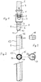
- Fig. 1 shows a universal joint with the joint parts 1, 2 and 3.
- the reference numeral 4 denotes the extension, which in engages the shutter and blind drive. In particular, this can done by an outstanding from this pen, which in a bore 5 of the extension 4 engages. But here are too other design options conceivable, depending on the type of Roller shutters can be designed.
- Extension 6 attached to the hinge part 3, which has a transverse running and through hole 7 has.
- the extension 6 is not rotationally symmetrical with respect to the urinary axis 9 of the universal joint part 3 and of the extension 6. Rather, a cross section is missing in the cross section.
- Reference number 10 denotes an insertion aid, which includes a slope; the others are still Front edges 11 of the extension 6 beveled.
- Fig. 2 shows a crank tube 12 which cooperates is designed with the extension 6.
- the crank tube 12 has via a jacket wall, which can be seen in particular in cross section 13, which pierce the crank tube 12 in the longitudinal direction Surrounding cavity 14.
- the Cavity 14 is not rotationally symmetrical, but not one Drilled paragraph 15 in the form of a circular section.
- 2 3 16 of the crank tube 12 is a through the circle segment 15 radially and transversely extending bore 17 introduced.
- the edge 16 of the crank tube 12 abuts the joint part 3.
- the holes 7 and 17 are aligned one above the other. Consequently it is a simple circlip shown in Fig. 3 18 to put the jacket 13 of the crank tube 12, wherein the one to be recognized in particular in the cross section of the locking ring 18 Pin 19 passes through the bore 17 and in the Hole 7 ends.
- the device is assembled as follows.
- the crank tube 12 is on the extension 6 pushed all the way. Because of the asymmetrical In the form of cavity 14 and extension 6 there is only one insertion possibility, their selection with the sloping surfaces 10 and 11 is promoted.
- the locking ring 18 with its two semi-circular ends 20 on average on the Mounted jacket 13 of the crank tube 12, the ends 20 expand by pressure and at the same time the pin 19 through the Openings 17 in the crank tube 12 and 7 in the extension 6 occurs until the inner wall of the locking ring 18 around the jacket of the crank tube 12 comes to rest.
- crank tube 12 instead of the flattening, any other shape of the recess can also be used can be selected in the crank tube 12.
- the crank tube 12 also consist of a solid material, only a non-rotationally symmetrical cavity in the end area near the joint is milled out.
- crank tube 12 It is also not necessary that the bore 17 through the thickened portion of the crank tube 12 leads. You can also any other thin cladding can be introduced then also to be provided in the extension 6 with the appropriate orientation is.
Landscapes
- Engineering & Computer Science (AREA)
- Structural Engineering (AREA)
- Architecture (AREA)
- Civil Engineering (AREA)
- Operating, Guiding And Securing Of Roll- Type Closing Members (AREA)
- Spinning Or Twisting Of Yarns (AREA)
- Earth Drilling (AREA)
Abstract
Description
- Fig. 1
- ein Kardangelenk mit einem Fortsatz zum Einschub in ein Kurbelrohr,
- Fig. 2
- ein Kurbelrohr in der Seitenansicht mit einer in die Zeichnung integrierten Querschnittsansicht, und
- Fig. 3
- eine Seitenansicht und eine Querschnittsansicht des Sicherungsringes für die Sicherungseinrichtung gemäss der Erfindung.
Claims (7)
- Sicherungseinrichtung für ein Kurbelrohr (12) zur Betätigung von Rolladen und Storen, das an einer Umlenkeinrichtung (1, 2 3) für einen Rolladenantrieb befestigbar ist, wobei das Kurbelrohr (12) zumindest in seinem der Umlenkeinrichtung (1, 2, 3) nahen Bereich hohl ist und eine quer verlaufende Bohrung (17) aufweist, wobei die Umlenkeinrichtung (1, 2, 3) über einen Fortsatz (6) verfügt, der eine weitere Bohrung (7) aufweist, und wobei ein Sicherungselement (18, 19) vorgesehen ist, das durch die beiden Bohrungen (7, 17) hindurch einsetzbar ist, dadurch gekennzeichnet, dass das hohle Kurbelrohr (12) über einen bezüglich der Achse des Kurbelrohrs (12) nicht rotationssymmetrischen Hohlraum (14) verfügt, dass der an der Umlenkeinrichtung (1, 2, 3) befindliche Fortsatz (6) komplementär entsprechend dem nicht rotationssymmetrischen Hohlraum (14) für eine passgenaue Einführung in denselben ausgestaltet ist, und dass das Sicherungselement (18, 19) aus einem Sicherungsring (18) mit einem radial nach innen ragenden Stift (19) besteht und dass mit diesem Stift (19) die Bohrungen (17 und 7) im Kurbelrohr (12) und im Fortsatz (6) des Gelenkes (1, 2, 3) durchstossbar sind.
- Sicherungseinrichtung nach Anspruch 1, dadurch gekennzeichnet, dass der Fortsatz (6) im wesentlichen zylindrisch ist und die Abweichung von der rotationssymmetrischen Form in einer Abflachung (8) liegt und dass der komplementäre und nicht rotationssymmetrische Hohlraum (14) eine im Querschnitt kreisabschnittförmige Stufe (15) aufweist.
- Sicherungseinrichtung nach Anspruch 2, dadurch gekennzeichnet, dass die Bohrung (17) durch das Kurbelrohr (12) durch die Stufe (15) vorgesehen ist.
- Sicherungseinrichtung nach einem der Ansprüche 1 bis 3, dadurch gekennzeichnet, dass das Kurbelrohr (12) im wesentlichen entlang seiner gesamten Längsachse (9) durchgehend den nicht rotationssymmetrischen Hohlraum (14) aufweist.
- Sicherungseinrichtung nach einem der Ansprüche 1 bis 4, dadurch gekennzeichnet, dass der Sicherungsring (18) auf der dem Stift (19) gegenüberliegenden Seite offen und nicht ganz geschlossen ist.
- Sicherungseinrichtung nach Anspruch 5, dadurch gekennzeichnet, dass der Innendurchmesser des Sicherungsringes (18) etwas kleiner als der Aussendurchmesser des Mantels (13) des Kurbelrohrs (12) im Bereich der Umlenkeinrichtung ist.
- Sicherungseinrichtung nach einem der Ansprüche 1 bis 6, dadurch gekennzeichnet, dass der Sicherungsring (18) aus Kunststoff ist.
Priority Applications (3)
| Application Number | Priority Date | Filing Date | Title |
|---|---|---|---|
| DE59808358T DE59808358D1 (de) | 1998-04-09 | 1998-04-09 | Sicherungseinrichtung für ein Kurbelrohr zur Betätigung von Rolladen und Storen |
| EP98810310A EP0949402B1 (de) | 1998-04-09 | 1998-04-09 | Sicherungseinrichtung für ein Kurbelrohr zur Betätigung von Rolladen und Storen |
| AT98810310T ATE240450T1 (de) | 1998-04-09 | 1998-04-09 | Sicherungseinrichtung für ein kurbelrohr zur betätigung von rolladen und storen |
Applications Claiming Priority (1)
| Application Number | Priority Date | Filing Date | Title |
|---|---|---|---|
| EP98810310A EP0949402B1 (de) | 1998-04-09 | 1998-04-09 | Sicherungseinrichtung für ein Kurbelrohr zur Betätigung von Rolladen und Storen |
Publications (2)
| Publication Number | Publication Date |
|---|---|
| EP0949402A1 true EP0949402A1 (de) | 1999-10-13 |
| EP0949402B1 EP0949402B1 (de) | 2003-05-14 |
Family
ID=8236033
Family Applications (1)
| Application Number | Title | Priority Date | Filing Date |
|---|---|---|---|
| EP98810310A Expired - Lifetime EP0949402B1 (de) | 1998-04-09 | 1998-04-09 | Sicherungseinrichtung für ein Kurbelrohr zur Betätigung von Rolladen und Storen |
Country Status (3)
| Country | Link |
|---|---|
| EP (1) | EP0949402B1 (de) |
| AT (1) | ATE240450T1 (de) |
| DE (1) | DE59808358D1 (de) |
Cited By (2)
| Publication number | Priority date | Publication date | Assignee | Title |
|---|---|---|---|---|
| DE10204964A1 (de) * | 2002-02-06 | 2003-08-14 | Geiger Gerhard Gmbh & Co | Kraftübertragungsvorrichtung |
| FR2908450A1 (fr) * | 2006-11-10 | 2008-05-16 | Zurfluh Feller Soc Par Actions | Dispositif de fixation d'une tringle de manivelle de volet roulant |
Citations (3)
| Publication number | Priority date | Publication date | Assignee | Title |
|---|---|---|---|---|
| EP0182950A1 (de) * | 1984-11-29 | 1986-06-04 | E. KINDT AG, vormals Hans Kiefer AG | Antriebsvorrichtung für eine Jalousie für Sonnen- und/oder Wetterschutz |
| DE9005759U1 (de) * | 1990-05-21 | 1990-09-06 | Antriebstechnik Gerhard Geiger GmbH & Co., 7120 Bietigheim-Bissingen | Kurbel |
| FR2697576A1 (fr) * | 1992-10-29 | 1994-05-06 | Simu | Dispositif de manivelle démontable pour la manÓoeuvre des stores et fermetures similaires. |
-
1998
- 1998-04-09 DE DE59808358T patent/DE59808358D1/de not_active Expired - Lifetime
- 1998-04-09 AT AT98810310T patent/ATE240450T1/de not_active IP Right Cessation
- 1998-04-09 EP EP98810310A patent/EP0949402B1/de not_active Expired - Lifetime
Patent Citations (3)
| Publication number | Priority date | Publication date | Assignee | Title |
|---|---|---|---|---|
| EP0182950A1 (de) * | 1984-11-29 | 1986-06-04 | E. KINDT AG, vormals Hans Kiefer AG | Antriebsvorrichtung für eine Jalousie für Sonnen- und/oder Wetterschutz |
| DE9005759U1 (de) * | 1990-05-21 | 1990-09-06 | Antriebstechnik Gerhard Geiger GmbH & Co., 7120 Bietigheim-Bissingen | Kurbel |
| FR2697576A1 (fr) * | 1992-10-29 | 1994-05-06 | Simu | Dispositif de manivelle démontable pour la manÓoeuvre des stores et fermetures similaires. |
Cited By (2)
| Publication number | Priority date | Publication date | Assignee | Title |
|---|---|---|---|---|
| DE10204964A1 (de) * | 2002-02-06 | 2003-08-14 | Geiger Gerhard Gmbh & Co | Kraftübertragungsvorrichtung |
| FR2908450A1 (fr) * | 2006-11-10 | 2008-05-16 | Zurfluh Feller Soc Par Actions | Dispositif de fixation d'une tringle de manivelle de volet roulant |
Also Published As
| Publication number | Publication date |
|---|---|
| EP0949402B1 (de) | 2003-05-14 |
| ATE240450T1 (de) | 2003-05-15 |
| DE59808358D1 (de) | 2003-06-18 |
Similar Documents
| Publication | Publication Date | Title |
|---|---|---|
| DE69731668T2 (de) | Bedienungsstab für bedeckungen von gebäudeöffnungen | |
| DE202018105095U1 (de) | Tür- und Treppenschutzgitter mit ausrollbarer Trennwand | |
| DE202018101267U1 (de) | Lamellenwinkeleinstellmechanismus für Jalousie | |
| EP0111790B1 (de) | Fensteraufsteller | |
| WO2009074190A1 (de) | Adapter zur anlenkung einer stange wie verriegelungsstange eines stangenverschlusses an einen hebel wie betätigungshebel des stangenverschlusses | |
| EP0949402B1 (de) | Sicherungseinrichtung für ein Kurbelrohr zur Betätigung von Rolladen und Storen | |
| DE2359471A1 (de) | Schutzvorrichtung fuer fenster in form einer jalousie oder eines rolladens | |
| DE202008011500U1 (de) | Luftschleieranlage | |
| DE3606554A1 (de) | Federelement zum verbinden des panzers eines rolladens mit der rolladenwelle | |
| DE19807050A1 (de) | Kraftübertragungsvorrichtung für die Betätigung eines Vorhangs | |
| DE2617505A1 (de) | Rolljalousie | |
| EP1267031A1 (de) | Sicherungseinrichtung für Rolläden oder dergleichen | |
| DE9414983U1 (de) | Bedienungsgriff | |
| EP1532913A2 (de) | Einrichtung zum Dämpfen von WC-Sitzen und/oder WC-Deckeln | |
| DE636861C (de) | Fensteraufstellvorrichtung | |
| DE102014015381A1 (de) | Griffanordnung für ein Fenster oder dergleichen sowie Fenster oder dergleichen mit Griffanordnung | |
| DE3405379C1 (de) | Schädeltrepan | |
| EP1091069A2 (de) | Scharnier mit zwei relativ zueinander um eine gemeinsame Drehachse verdrehbaren Scharnierteilen | |
| EP2317164A1 (de) | Haken, insbesondere für Sicherheitseinrichtungen | |
| DE102019102441A1 (de) | Vorreiber zum Verriegeln einer Tür | |
| EP2224091A2 (de) | Wendelager für Storen mit Lamellenelementen | |
| DE102009016791A1 (de) | Insektenschutztür oder -fenster | |
| EP3130733B1 (de) | Scharniergelenk, insbesondere für fenster, türen oder dergleichen | |
| EP1734212B1 (de) | Beschlaganordnung | |
| DE10138065B4 (de) | Federbelasteter Umleggriff |
Legal Events
| Date | Code | Title | Description |
|---|---|---|---|
| PUAI | Public reference made under article 153(3) epc to a published international application that has entered the european phase |
Free format text: ORIGINAL CODE: 0009012 |
|
| AK | Designated contracting states |
Kind code of ref document: A1 Designated state(s): AT CH DE FR IT LI |
|
| AX | Request for extension of the european patent |
Free format text: AL;LT;LV;MK;RO;SI |
|
| 17P | Request for examination filed |
Effective date: 20000315 |
|
| AKX | Designation fees paid |
Free format text: AT CH DE FR IT LI |
|
| 17Q | First examination report despatched |
Effective date: 20020617 |
|
| GRAH | Despatch of communication of intention to grant a patent |
Free format text: ORIGINAL CODE: EPIDOS IGRA |
|
| GRAH | Despatch of communication of intention to grant a patent |
Free format text: ORIGINAL CODE: EPIDOS IGRA |
|
| GRAA | (expected) grant |
Free format text: ORIGINAL CODE: 0009210 |
|
| AK | Designated contracting states |
Designated state(s): AT CH DE FR IT LI |
|
| REG | Reference to a national code |
Ref country code: CH Ref legal event code: EP |
|
| REF | Corresponds to: |
Ref document number: 59808358 Country of ref document: DE Date of ref document: 20030618 Kind code of ref document: P |
|
| REG | Reference to a national code |
Ref country code: CH Ref legal event code: NV Representative=s name: ING. HANS LUDESCHER, PATENTABTEILUNG DER SFS GRUPP |
|
| PLBE | No opposition filed within time limit |
Free format text: ORIGINAL CODE: 0009261 |
|
| STAA | Information on the status of an ep patent application or granted ep patent |
Free format text: STATUS: NO OPPOSITION FILED WITHIN TIME LIMIT |
|
| ET | Fr: translation filed | ||
| 26N | No opposition filed |
Effective date: 20040217 |
|
| PGFP | Annual fee paid to national office [announced via postgrant information from national office to epo] |
Ref country code: FR Payment date: 20050310 Year of fee payment: 8 |
|
| REG | Reference to a national code |
Ref country code: FR Ref legal event code: ST Effective date: 20061230 |
|
| REG | Reference to a national code |
Ref country code: CH Ref legal event code: PCAR Free format text: ISLER & PEDRAZZINI AG;POSTFACH 1772;8027 ZUERICH (CH) |
|
| PG25 | Lapsed in a contracting state [announced via postgrant information from national office to epo] |
Ref country code: FR Free format text: LAPSE BECAUSE OF NON-PAYMENT OF DUE FEES Effective date: 20060502 |
|
| PGFP | Annual fee paid to national office [announced via postgrant information from national office to epo] |
Ref country code: AT Payment date: 20100415 Year of fee payment: 13 |
|
| REG | Reference to a national code |
Ref country code: CH Ref legal event code: PUE Owner name: KE STORATEX AG Free format text: STORATEX AG#ROEMERWEG 1#4800 ZOFINGEN (CH) -TRANSFER TO- KE STORATEX AG#KREUZMATTE 1A#6260 REIDEN (CH) |
|
| REG | Reference to a national code |
Ref country code: AT Ref legal event code: MM01 Ref document number: 240450 Country of ref document: AT Kind code of ref document: T Effective date: 20110409 |
|
| PG25 | Lapsed in a contracting state [announced via postgrant information from national office to epo] |
Ref country code: AT Free format text: LAPSE BECAUSE OF NON-PAYMENT OF DUE FEES Effective date: 20110409 |
|
| REG | Reference to a national code |
Ref country code: CH Ref legal event code: PFA Owner name: RS SUNTEC SYSTEME AG, CH Free format text: FORMER OWNER: KE STORATEX AG, CH |
|
| PGFP | Annual fee paid to national office [announced via postgrant information from national office to epo] |
Ref country code: CH Payment date: 20170321 Year of fee payment: 20 |
|
| PGFP | Annual fee paid to national office [announced via postgrant information from national office to epo] |
Ref country code: DE Payment date: 20170419 Year of fee payment: 20 |
|
| PGFP | Annual fee paid to national office [announced via postgrant information from national office to epo] |
Ref country code: IT Payment date: 20170420 Year of fee payment: 20 |
|
| REG | Reference to a national code |
Ref country code: DE Ref legal event code: R071 Ref document number: 59808358 Country of ref document: DE |
|
| REG | Reference to a national code |
Ref country code: CH Ref legal event code: PL |