EP0949053A1 - Procédé et dispositif pour co-injecter des produits multicouches - Google Patents
Procédé et dispositif pour co-injecter des produits multicouches Download PDFInfo
- Publication number
- EP0949053A1 EP0949053A1 EP98830210A EP98830210A EP0949053A1 EP 0949053 A1 EP0949053 A1 EP 0949053A1 EP 98830210 A EP98830210 A EP 98830210A EP 98830210 A EP98830210 A EP 98830210A EP 0949053 A1 EP0949053 A1 EP 0949053A1
- Authority
- EP
- European Patent Office
- Prior art keywords
- injection
- nozzles
- points
- nozzle
- materials
- Prior art date
- Legal status (The legal status is an assumption and is not a legal conclusion. Google has not performed a legal analysis and makes no representation as to the accuracy of the status listed.)
- Withdrawn
Links
Images

Classifications
-
- B—PERFORMING OPERATIONS; TRANSPORTING
- B29—WORKING OF PLASTICS; WORKING OF SUBSTANCES IN A PLASTIC STATE IN GENERAL
- B29C—SHAPING OR JOINING OF PLASTICS; SHAPING OF MATERIAL IN A PLASTIC STATE, NOT OTHERWISE PROVIDED FOR; AFTER-TREATMENT OF THE SHAPED PRODUCTS, e.g. REPAIRING
- B29C45/00—Injection moulding, i.e. forcing the required volume of moulding material through a nozzle into a closed mould; Apparatus therefor
- B29C45/16—Making multilayered or multicoloured articles
- B29C45/1642—Making multilayered or multicoloured articles having a "sandwich" structure
-
- B—PERFORMING OPERATIONS; TRANSPORTING
- B29—WORKING OF PLASTICS; WORKING OF SUBSTANCES IN A PLASTIC STATE IN GENERAL
- B29C—SHAPING OR JOINING OF PLASTICS; SHAPING OF MATERIAL IN A PLASTIC STATE, NOT OTHERWISE PROVIDED FOR; AFTER-TREATMENT OF THE SHAPED PRODUCTS, e.g. REPAIRING
- B29C45/00—Injection moulding, i.e. forcing the required volume of moulding material through a nozzle into a closed mould; Apparatus therefor
- B29C45/0025—Preventing defects on the moulded article, e.g. weld lines, shrinkage marks
- B29C2045/0032—Preventing defects on the moulded article, e.g. weld lines, shrinkage marks sequential injection from multiple gates, e.g. to avoid weld lines
-
- B—PERFORMING OPERATIONS; TRANSPORTING
- B29—WORKING OF PLASTICS; WORKING OF SUBSTANCES IN A PLASTIC STATE IN GENERAL
- B29C—SHAPING OR JOINING OF PLASTICS; SHAPING OF MATERIAL IN A PLASTIC STATE, NOT OTHERWISE PROVIDED FOR; AFTER-TREATMENT OF THE SHAPED PRODUCTS, e.g. REPAIRING
- B29C45/00—Injection moulding, i.e. forcing the required volume of moulding material through a nozzle into a closed mould; Apparatus therefor
- B29C2045/0093—Injection moulding, i.e. forcing the required volume of moulding material through a nozzle into a closed mould; Apparatus therefor of articles provided with an attaching element
-
- B—PERFORMING OPERATIONS; TRANSPORTING
- B29—WORKING OF PLASTICS; WORKING OF SUBSTANCES IN A PLASTIC STATE IN GENERAL
- B29C—SHAPING OR JOINING OF PLASTICS; SHAPING OF MATERIAL IN A PLASTIC STATE, NOT OTHERWISE PROVIDED FOR; AFTER-TREATMENT OF THE SHAPED PRODUCTS, e.g. REPAIRING
- B29C45/00—Injection moulding, i.e. forcing the required volume of moulding material through a nozzle into a closed mould; Apparatus therefor
- B29C45/16—Making multilayered or multicoloured articles
- B29C45/1642—Making multilayered or multicoloured articles having a "sandwich" structure
- B29C2045/1651—Independent injection runners or nozzles
-
- B—PERFORMING OPERATIONS; TRANSPORTING
- B29—WORKING OF PLASTICS; WORKING OF SUBSTANCES IN A PLASTIC STATE IN GENERAL
- B29C—SHAPING OR JOINING OF PLASTICS; SHAPING OF MATERIAL IN A PLASTIC STATE, NOT OTHERWISE PROVIDED FOR; AFTER-TREATMENT OF THE SHAPED PRODUCTS, e.g. REPAIRING
- B29C45/00—Injection moulding, i.e. forcing the required volume of moulding material through a nozzle into a closed mould; Apparatus therefor
- B29C45/16—Making multilayered or multicoloured articles
- B29C45/1642—Making multilayered or multicoloured articles having a "sandwich" structure
- B29C2045/1654—Making multilayered or multicoloured articles having a "sandwich" structure whereby the core material is penetrating through the skin
-
- B—PERFORMING OPERATIONS; TRANSPORTING
- B29—WORKING OF PLASTICS; WORKING OF SUBSTANCES IN A PLASTIC STATE IN GENERAL
- B29L—INDEXING SCHEME ASSOCIATED WITH SUBCLASS B29C, RELATING TO PARTICULAR ARTICLES
- B29L2031/00—Other particular articles
- B29L2031/30—Vehicles, e.g. ships or aircraft, or body parts thereof
- B29L2031/3005—Body finishings
- B29L2031/3014—Door linings
-
- Y—GENERAL TAGGING OF NEW TECHNOLOGICAL DEVELOPMENTS; GENERAL TAGGING OF CROSS-SECTIONAL TECHNOLOGIES SPANNING OVER SEVERAL SECTIONS OF THE IPC; TECHNICAL SUBJECTS COVERED BY FORMER USPC CROSS-REFERENCE ART COLLECTIONS [XRACs] AND DIGESTS
- Y10—TECHNICAL SUBJECTS COVERED BY FORMER USPC
- Y10T—TECHNICAL SUBJECTS COVERED BY FORMER US CLASSIFICATION
- Y10T428/00—Stock material or miscellaneous articles
- Y10T428/31504—Composite [nonstructural laminate]
- Y10T428/31855—Of addition polymer from unsaturated monomers
Definitions
- the present invention relates to a process and device for the co-injection of multi-layer elements and the products thus obtained.
- the invention relates to the production of elements provided with at least one part having an external skin which covers an internal core material.
- Examples of such product are the internal panels and elements of motor vehicles.
- the European Patent N°0579925 in the name of the applicant, describes a device for co-injection provided with independently heated hot channels and nozzles located in the wall of the mould.
- the nozzles described may be either coaxial or side-by-side and allow two or more materials to be injected successively into the same mould cavity from a plurality of points.
- the thickness of the mould depends on the rheological properties of the material to be injected in order to give flow pathways with substantially the same resistance and thus achieve homogenous distribution of the material inside the mould.
- the materials are injected via nozzles for the sequential injection of two materials; in the preferred embodiment only one nozzle is used for a mould for a car panel.
- One aim of the present invention is to resolve the aforementioned problems and provide a simple and economical process for the co-injection of two or more materials to give products having at least in part an external skin and an internal core.
- a further aim of the invention is to provide a device for obtaining the process described above.
- only one material is injected at each point of injection and the materials are preferably injected in cascades.
- the invention relates furthermore to a device to injection-mould multi-layer products comprising two or more materials, according to Claim 6.
- a further object of the invention is the multi-layer product obtained by the process of the invention, according to Claim 11.
- the invention presents numerous advantages over processes from the present state of the art. There is a reduction of both injection pressure (so smaller and less expensive presses can be used) and molding-cycle time. Furthermore, junction lines between the various flows of material are eliminated and the mould can have substantially constant thickness for the greater part of its extent, if this does not conflict with the design requirements. The constant thickness results in greater facility of design and less weight in the finished product.
- Another advantage lies in being able to produce the fixing elements to assemble the panels onto the doors and counter-panels or complementary panels (keys and poppettes) in core material alone, i.e. rigid material. In this way soft materials can be chosen for the skin thus benefiting the 'feel' of the finished product.
- the present invention provides for a multi-point co-injection process of two or more materials in the same mould cavity, in which only one material is injected from at least one of the injection points, i.e. the supply to that point is a single material and there are no other materials delivered to that point.
- at least one of the points (and one of the nozzles) for the injection of the first material is different from and physically distinct from all the injection points of a second material (or any other material).
- This differs from the known process, which provides for the injection of two (or more) materials successively from the same injection point, using the some nozzle, where the two materials are injected through the same hole or from two side-by-side holes on the same nozzle (or injector).
- An "injection point" substantially corresponds to the mould area where the injection nozzle is in place.
- the dedicated nozzle is connected to a supply of only one material and has single-material supply lines.
- all the nozzles are of the dedicated type; which means that all the nozzles for the first material are different from all the nozzles of the second material (and in case that both such points of injection are different from those of successive materials).
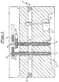
- Fig.1 shows the upper part of a mould 1, provided with a cavity 2 and two injection nozzles 3 and 4, which extend into the upper part of the mould 1.
- the nozzles 3 and 4 have supply channels 5 and 6 which can be heated by means 7 already known to the art, and rods 8 to control the feeding of the material into the mold cavity 2.
- the rods 8 move axially in a way known to the art, e.g. by oleodynamic piston, from a partially withdrawn position for injecting material to a "nozzle closed" position where the tip of the rod is substantially aligned with the nozzle opening.
- nozzles 3 and 4 are shown with both rods lowered in the 'nozzle closed' position.
- the rods 8 are only partially shown for the sake of clarity in the drawing.
- Both nozzle 3 and nozzle 4 are dedicated; i.e. they can inject only one type of material: channels 5 and 6 are connected respectively to the distributors 9 and 10, which receive their respective material from two injection units on the same press (not shown). Generally, the distributors 9 and 10 are also equipped with means of heating.
- the space 21 in the upper part of the mold 1 is for an extraction plate (not shown) for the expulsion of the molding in a manner already known.
- the nozzles 3 and 4 may be located either on the closing face of the mold immediately next to the mold cavity or in the mold cavity on the portion of the mold corresponding to the side of the molding which will not be visible when the product is in use; e.g. in the case of vehicle interior panels the nozzle side would be that which faces the bodywork on the assembled product.
- the latter nozzle arrangement is particularly useful inasmuch as it allows the injection pressure to be reduced.
- this arrangement is useful when the product is not to be painted or covered, in as much as there are different materials around the nozzles 3 and 4 in the finished product: the skin material is injected by nozzle 3 and the core material by nozzle 4. The surface of the panel will thus have a discontinuity in the skin around 4.
- the nozzles for the injection of the two materials are located relatively close to each other to give co-injection of the two materials.
- fig. 2 shows the reciprocal position of two groups of nozzles for the co-injection of a vehicle interior panel 11.
- the panel 11 is of the type comprising an integral handle with the rest of the body and is particularly complex in shape.
- the injection points for the two materials of skin and core are indicated by the numbers 3a - 3c for the skin nozzle and 4a - 4g for the core nozzles.
- the gas injection points 12 inject gas during the molding of the panel.
- the gas serves to create some "hollow" sectors to lighten the panel and to avoid any draw after the molding.
- the injection of gas during injection molding is a known technique for who is skilled in the art.
- each of the various nozzles is calculated bearing in mind the thickness and geometry of the mold cavity and the rheology of the materials injected.
- the distance between a skin nozzle and a core nozzle should be such as to prevent excessive cooling of the skin material already injected at the center of the section of the product.
- the distance between two adjacent nozzles for skin or care must be such as to allow the skin material to reach and extend beyond the core injection point in a sufficiently fluid state so that it can be driven and distributed in the mold by the core material when it is injected.
- Means of heating one or more parts of the mold can also be provided to facilitate the flow of the materials throughout the cavity.
- the 'keys' and 'poppettes' which allow the panel to be mounted on the door are shown as 13 and 13a respectively.
- the keys are brackets and the poppettes are pivots which project from the panel in pre-fixed positions.
- These brackets or keys can be molded as a single piece with the panel by means of a slide valve mechanism actuated by a jack 14 (fig.1) which closes a part of the mould related to keys or poppettes during the injection of the skin material.
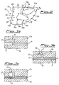
- Figs. 3a - 3c show the operation of the mechanism during molding to form a key.
- the mechanism comprises a slide valve 21 which is moved by the jack 14 (fig.1) in a way already known in the art, to close at will the portion of the mould corresponding to the key 13 and to isolate it from the mold cavity 2.
- the upper and lower parts of the mold 1 are referred to as 1a and 1b respectively.
- the slide valve is closed during the injection of the skin material, preventing the said material P from entering the cavity area 15.
- the second phase of the procedure (fig. 3b) provides for the opening of the slide valve to allow the cavity 15 to fill up with core material C.
- the slide valve is brought to the fig.3b position when the material C reaches the cavity 15.
- the last phase is shown in fig.3c and occurs when molding has been completed; this entails the further withdrawal of the slide valve to clear the overhang of the key and allow it to be removed from the mold.
- the slide valve also has the function of expelling the poppette to facilitate the removal of the panel from the mold.
- FIG. 4 shows a schematic embodiment to implement the process of the invention.
- an electronic processing means 22 e.g. a plc unit
- sensors 23 or other means of detecting the advance of the material front in the mold 1 and sending a correspondent signal when the material has reached a pre-selected point.
- sensors are preferably transducers.
- the unit 22 is also connected to the press 24 to detect the height of the screws and to the nozzles 3 and 4 to trigger their operation at the right moment.
- the process according to the invention operates in the following manner.
- a predetermined quantity of skin material is injected through the injection nozzles 3a - 3c.
- the quantity of material injected is substantially that of the skin on the molded product and it extends inside the mold until it reaches and covers the areas where the nozzles for injecting the core material 4a - 4g are located. Then the core material is injected.
- the skin material is pushed and distributed around the mould by the core material injected through its related nozzles 4a - 4g, which, as shown, are more numerous than the skin nozzles.
- At least the skin nozzles are activated in cascade according to timing controlled by the travel height of the screws in the injection press; in this way the junction lines between different flows arriving from different nozzles are more easily eliminated in that the flow from each nozzle merges into the initial flow once that flow passes the nozzle position.
- nozzle 3b is not activated until the skin material flow P from nozzle 3a has already reached - and preferably passed - nozzle 3b, and so on for all the nozzles.
- nozzle 3a operates from screw height 150 to height 98; 3b from height 100 to height 58; 3c from height 60 to height 10 (end of screw travel).
- the nozzles 4a - 4g are operated in a similar way and as a function of the reciprocal position i.e. out of seven nozzles there can be two branching "sequences".
- some core nozzles are activated before some of the skin nozzles, depending on their position in the mold.
- the skin nozzle e.g. 3a
- the core nozzle e.g. 4b
- the core nozzle e.g. 4c
- the skin to core ratio was about 50/50 (by weight) and the injection temperature was 220-230°C for the skin and 190°C for the core.
- a slide-valve mechanism in combination with a group of nozzles according to the invention produced a moldings of the type shown.
- Fig 5 shows three nozzles; the center nozzle 16 is dedicated to injecting only skin material A while the side injectors 17 are two-material co-injection type to supply either A or B.
- Two slide-valve mechanisms or similar means of temporarily closing the portion 20 and 20a of the mold are in place at 18 and 19 and are activated before the injection of the material A from the nozzle 16. Material A fills the central portion of the mold completely and the side portion 20 and 20a partially. Next, the slider are removed and the material B is injected by nozzle 17.
Landscapes
- Engineering & Computer Science (AREA)
- Manufacturing & Machinery (AREA)
- Mechanical Engineering (AREA)
- Injection Moulding Of Plastics Or The Like (AREA)
Priority Applications (6)
| Application Number | Priority Date | Filing Date | Title |
|---|---|---|---|
| EP98830210A EP0949053A1 (fr) | 1998-04-07 | 1998-04-07 | Procédé et dispositif pour co-injecter des produits multicouches |
| AU38130/99A AU3813099A (en) | 1998-04-07 | 1999-04-06 | Process and device for co-injection molding multilayer products |
| US09/647,785 US6475413B1 (en) | 1998-04-07 | 1999-04-06 | Process and device for co-injection molding multilayer products |
| EP99920599A EP1069979A1 (fr) | 1998-04-07 | 1999-04-06 | Procede et dispositif destines au moulage par co-injection de produits multicouches |
| PCT/EP1999/002329 WO1999051416A1 (fr) | 1998-04-07 | 1999-04-06 | Procede et dispositif destines au moulage par co-injection de produits multicouches |
| US10/241,538 US20030012837A1 (en) | 1998-04-07 | 2002-09-12 | Process and device for coinjection molding multilayer products |
Applications Claiming Priority (1)
| Application Number | Priority Date | Filing Date | Title |
|---|---|---|---|
| EP98830210A EP0949053A1 (fr) | 1998-04-07 | 1998-04-07 | Procédé et dispositif pour co-injecter des produits multicouches |
Publications (1)
| Publication Number | Publication Date |
|---|---|
| EP0949053A1 true EP0949053A1 (fr) | 1999-10-13 |
Family
ID=8236610
Family Applications (2)
| Application Number | Title | Priority Date | Filing Date |
|---|---|---|---|
| EP98830210A Withdrawn EP0949053A1 (fr) | 1998-04-07 | 1998-04-07 | Procédé et dispositif pour co-injecter des produits multicouches |
| EP99920599A Withdrawn EP1069979A1 (fr) | 1998-04-07 | 1999-04-06 | Procede et dispositif destines au moulage par co-injection de produits multicouches |
Family Applications After (1)
| Application Number | Title | Priority Date | Filing Date |
|---|---|---|---|
| EP99920599A Withdrawn EP1069979A1 (fr) | 1998-04-07 | 1999-04-06 | Procede et dispositif destines au moulage par co-injection de produits multicouches |
Country Status (4)
| Country | Link |
|---|---|
| US (2) | US6475413B1 (fr) |
| EP (2) | EP0949053A1 (fr) |
| AU (1) | AU3813099A (fr) |
| WO (1) | WO1999051416A1 (fr) |
Cited By (8)
| Publication number | Priority date | Publication date | Assignee | Title |
|---|---|---|---|---|
| WO2001062488A1 (fr) | 2000-02-24 | 2001-08-30 | Conix Corporation | Composants de vehicule moules par co-injection et leurs procedes de fabrication |
| US6843954B2 (en) | 2000-02-24 | 2005-01-18 | Conix Corporation | Injection molding techniques utilizing fluid channels |
| US6998174B2 (en) | 2000-02-24 | 2006-02-14 | Conix Corporation | Integrated co-injection molded vehicle components and methods of making the same |
| DE102005026790A1 (de) * | 2005-06-10 | 2006-12-21 | Bayerische Motoren Werke Ag | Spritzgussverfahren zur Herstellung eines flächigen Kunststoffteils |
| WO2007149021A1 (fr) | 2006-06-21 | 2007-12-27 | Flexiject Co-Injection Ab | Procédé de moulage par injection de produits en matière thermoplastique avec ouverture par étages de différentes parties de la cavité du moule, et outil permettant d'utiliser le procédé |
| US20130221572A1 (en) * | 2012-02-24 | 2013-08-29 | The Procter & Gamble Company | High Thermal Conductivity Co-Injection Molding System |
| WO2016126471A1 (fr) * | 2015-02-02 | 2016-08-11 | Colgate-Palmolive Company | Système et procédé de formation d'un instrument de soin buccal |
| EP3878622A1 (fr) * | 2020-03-10 | 2021-09-15 | Adval Tech Holding AG | Outil de moulage par injection, leurs utilisations et de pièces fabriquées avec un tel outil |
Families Citing this family (13)
| Publication number | Priority date | Publication date | Assignee | Title |
|---|---|---|---|---|
| JP4553512B2 (ja) * | 2000-04-28 | 2010-09-29 | 三菱エンジニアリングプラスチックス株式会社 | 中空部を有する成形品の射出成形方法 |
| US20030211307A1 (en) * | 2001-02-23 | 2003-11-13 | Porter Marshall Ray | Low-density injection-molded body components |
| FR2824136B1 (fr) * | 2001-04-27 | 2003-05-30 | Schlumberger Ind Sa | Procede de fabrication d'un compteur de liquide volumetrique du type a piston oscillant |
| CN100513123C (zh) * | 2003-08-25 | 2009-07-15 | 约翰逊控制技术公司 | 装饰板的多部件注射模制 |
| WO2005068152A2 (fr) * | 2004-01-03 | 2005-07-28 | Johnson Controls Technology Company | Piece de vehicule et procede pour realiser une piece de vehicule |
| US20060216479A1 (en) * | 2005-03-22 | 2006-09-28 | Lear Corporation | Two-shot, co-injected trim panel |
| FR2901504B1 (fr) * | 2006-05-29 | 2012-10-26 | Plastigray | Procede de fabrication d'une piece injectee, dispositif pour la mise en oeuvre de ce procede et piece obtenue |
| US7651644B2 (en) * | 2006-05-31 | 2010-01-26 | Graham Packaging Company, Lp | Controlling delivery of polymer material in a sequential injection molding process |
| WO2010054188A1 (fr) * | 2008-11-10 | 2010-05-14 | Illinois Tool Works Inc. | Procédé de moulage par co-injection et pièces formées par ce moyen |
| US8844198B2 (en) * | 2009-08-28 | 2014-09-30 | Inteva Products, Llc | Multilayer window lift rail, and apparatus and method for making the same |
| DE102009055157A1 (de) * | 2009-12-22 | 2011-06-30 | ElringKlinger AG, 72581 | Verfahren zum Herstellen eines Grundkörpers einer Ölwanne und durch ein solches Verfahren hergestellter Grundkörper einer Ölwanne |
| US8715547B2 (en) | 2011-02-24 | 2014-05-06 | Mold-Masters (2007) Limited | Closed loop control of auxiliary injection unit |
| US10645357B2 (en) * | 2018-03-01 | 2020-05-05 | Motorola Mobility Llc | Selectively applying color to an image |
Citations (11)
| Publication number | Priority date | Publication date | Assignee | Title |
|---|---|---|---|---|
| GB1339444A (en) * | 1970-11-30 | 1973-12-05 | Ici Ltd | Production of laminar articles |
| GB1339445A (en) * | 1970-11-30 | 1973-12-05 | Ici Ltd | Production of laminar articles |
| US3873656A (en) * | 1967-12-15 | 1975-03-25 | Ici Ltd | Production of laminar articles |
| DE3711079A1 (de) * | 1987-04-02 | 1988-10-13 | Battenfeld Gmbh | Verfahren und vorrichtung zum spritzgiessen von formteilen aus mindestens zwei verschiedenen kunststoffkomponenten |
| JPH02206518A (ja) * | 1989-02-03 | 1990-08-16 | Toyoda Gosei Co Ltd | プラスチック成形品の成形方法 |
| US5046942A (en) * | 1990-11-19 | 1991-09-10 | Gellert Jobst U | Injection molding nozzle having tapered heating element adjacent the bore |
| JPH06312437A (ja) * | 1993-04-28 | 1994-11-08 | Toyoda Gosei Co Ltd | 取付座を有するサンドイッチ成形品及びその成形方法 |
| JPH07117081A (ja) * | 1993-10-22 | 1995-05-09 | Toyoda Gosei Co Ltd | サンドイッチ成形用の金型装置 |
| EP0688652A1 (fr) * | 1994-06-06 | 1995-12-27 | Husky Injection Molding Systems Ltd. | Procédé de moulage par injection avec entrées d'injection opposées |
| EP0704290A1 (fr) * | 1994-09-01 | 1996-04-03 | Sumitomo Chemical Company Limited | Procédé de fabrication de pièces moulées en matière thermoplastique |
| JPH08174603A (ja) * | 1994-12-22 | 1996-07-09 | Japan Steel Works Ltd:The | 複合成形方法及び射出成形機 |
Family Cites Families (8)
| Publication number | Priority date | Publication date | Assignee | Title |
|---|---|---|---|---|
| US4275030A (en) * | 1978-05-10 | 1981-06-23 | Pedro Mares | Injection molding articles of more than one resin component |
| US4385025A (en) * | 1979-10-22 | 1983-05-24 | Barry Wright Corporation | Method of coinjection molding of thermoplastic and thermoplastic elastomer |
| DE4110445C2 (de) * | 1991-03-26 | 1994-10-27 | Mannesmann Ag | Verfahren und Vorrichtung zur Herstellung dekorbeschichteter Kunststoff-Formteile |
| JPH04318383A (ja) * | 1991-04-17 | 1992-11-09 | Fuji Photo Film Co Ltd | 磁気テープカセット及びその製法 |
| US5799385A (en) * | 1991-12-10 | 1998-09-01 | Commer S.P.A. | Process for the manufacture of trim panels for motorvehicles |
| IT1254989B (it) | 1992-06-23 | 1995-10-11 | Dante Siano | Dispositivo per la coiniezione in punti distinti di uno stampo |
| DE19518963C2 (de) * | 1995-05-23 | 1998-04-09 | Eldra Kunststofftechnik Gmbh | Verfahren und Vorrichtung zum Spritzgießen hohlgeblasener Kunststoffkörper |
| CN1158740A (zh) | 1996-10-23 | 1997-09-10 | 向薇 | 一种具有溶石作用的药物 |
-
1998
- 1998-04-07 EP EP98830210A patent/EP0949053A1/fr not_active Withdrawn
-
1999
- 1999-04-06 WO PCT/EP1999/002329 patent/WO1999051416A1/fr not_active Application Discontinuation
- 1999-04-06 AU AU38130/99A patent/AU3813099A/en not_active Abandoned
- 1999-04-06 US US09/647,785 patent/US6475413B1/en not_active Expired - Fee Related
- 1999-04-06 EP EP99920599A patent/EP1069979A1/fr not_active Withdrawn
-
2002
- 2002-09-12 US US10/241,538 patent/US20030012837A1/en not_active Abandoned
Patent Citations (11)
| Publication number | Priority date | Publication date | Assignee | Title |
|---|---|---|---|---|
| US3873656A (en) * | 1967-12-15 | 1975-03-25 | Ici Ltd | Production of laminar articles |
| GB1339444A (en) * | 1970-11-30 | 1973-12-05 | Ici Ltd | Production of laminar articles |
| GB1339445A (en) * | 1970-11-30 | 1973-12-05 | Ici Ltd | Production of laminar articles |
| DE3711079A1 (de) * | 1987-04-02 | 1988-10-13 | Battenfeld Gmbh | Verfahren und vorrichtung zum spritzgiessen von formteilen aus mindestens zwei verschiedenen kunststoffkomponenten |
| JPH02206518A (ja) * | 1989-02-03 | 1990-08-16 | Toyoda Gosei Co Ltd | プラスチック成形品の成形方法 |
| US5046942A (en) * | 1990-11-19 | 1991-09-10 | Gellert Jobst U | Injection molding nozzle having tapered heating element adjacent the bore |
| JPH06312437A (ja) * | 1993-04-28 | 1994-11-08 | Toyoda Gosei Co Ltd | 取付座を有するサンドイッチ成形品及びその成形方法 |
| JPH07117081A (ja) * | 1993-10-22 | 1995-05-09 | Toyoda Gosei Co Ltd | サンドイッチ成形用の金型装置 |
| EP0688652A1 (fr) * | 1994-06-06 | 1995-12-27 | Husky Injection Molding Systems Ltd. | Procédé de moulage par injection avec entrées d'injection opposées |
| EP0704290A1 (fr) * | 1994-09-01 | 1996-04-03 | Sumitomo Chemical Company Limited | Procédé de fabrication de pièces moulées en matière thermoplastique |
| JPH08174603A (ja) * | 1994-12-22 | 1996-07-09 | Japan Steel Works Ltd:The | 複合成形方法及び射出成形機 |
Non-Patent Citations (4)
| Title |
|---|
| PATENT ABSTRACTS OF JAPAN vol. 14, no. 501 (M - 1043) 2 November 1990 (1990-11-02) * |
| PATENT ABSTRACTS OF JAPAN vol. 95, no. 2 31 March 1995 (1995-03-31) * |
| PATENT ABSTRACTS OF JAPAN vol. 95, no. 8 29 September 1995 (1995-09-29) * |
| PATENT ABSTRACTS OF JAPAN vol. 96, no. 11 29 November 1996 (1996-11-29) * |
Cited By (15)
| Publication number | Priority date | Publication date | Assignee | Title |
|---|---|---|---|---|
| EP1263574A1 (fr) * | 2000-02-24 | 2002-12-11 | Conix Corporation | Composants de vehicule moules par co-injection et leurs procedes de fabrication |
| EP1263574A4 (fr) * | 2000-02-24 | 2003-05-02 | Conix Corp | Composants de vehicule moules par co-injection et leurs procedes de fabrication |
| US6843954B2 (en) | 2000-02-24 | 2005-01-18 | Conix Corporation | Injection molding techniques utilizing fluid channels |
| US6998174B2 (en) | 2000-02-24 | 2006-02-14 | Conix Corporation | Integrated co-injection molded vehicle components and methods of making the same |
| WO2001062488A1 (fr) | 2000-02-24 | 2001-08-30 | Conix Corporation | Composants de vehicule moules par co-injection et leurs procedes de fabrication |
| DE102005026790B4 (de) * | 2005-06-10 | 2016-06-09 | Bayerische Motoren Werke Aktiengesellschaft | Spritzgussverfahren zur Herstellung eines flächigen Kunststoffteils |
| DE102005026790A1 (de) * | 2005-06-10 | 2006-12-21 | Bayerische Motoren Werke Ag | Spritzgussverfahren zur Herstellung eines flächigen Kunststoffteils |
| WO2007149021A1 (fr) | 2006-06-21 | 2007-12-27 | Flexiject Co-Injection Ab | Procédé de moulage par injection de produits en matière thermoplastique avec ouverture par étages de différentes parties de la cavité du moule, et outil permettant d'utiliser le procédé |
| EP2035206A4 (fr) * | 2006-06-21 | 2014-05-21 | Flexiject Co Injection Ab | Procédé de moulage par injection de produits en matière thermoplastique avec ouverture par étages de différentes parties de la cavité du moule, et outil permettant d'utiliser le procédé |
| EP2035206A1 (fr) * | 2006-06-21 | 2009-03-18 | Flexiject Co-Injection AB | Procédé de moulage par injection de produits en matière thermoplastique avec ouverture par étages de différentes parties de la cavité du moule, et outil permettant d'utiliser le procédé |
| US20130221572A1 (en) * | 2012-02-24 | 2013-08-29 | The Procter & Gamble Company | High Thermal Conductivity Co-Injection Molding System |
| WO2016126471A1 (fr) * | 2015-02-02 | 2016-08-11 | Colgate-Palmolive Company | Système et procédé de formation d'un instrument de soin buccal |
| US10723052B2 (en) | 2015-02-02 | 2020-07-28 | Colgate-Palmolive Company | System and method for forming an oral care implement |
| US11577435B2 (en) | 2015-02-02 | 2023-02-14 | Colgate-Palmolive Company | System and method for forming an oral care implement |
| EP3878622A1 (fr) * | 2020-03-10 | 2021-09-15 | Adval Tech Holding AG | Outil de moulage par injection, leurs utilisations et de pièces fabriquées avec un tel outil |
Also Published As
| Publication number | Publication date |
|---|---|
| US20030012837A1 (en) | 2003-01-16 |
| EP1069979A1 (fr) | 2001-01-24 |
| WO1999051416A1 (fr) | 1999-10-14 |
| AU3813099A (en) | 1999-10-25 |
| US6475413B1 (en) | 2002-11-05 |
Similar Documents
| Publication | Publication Date | Title |
|---|---|---|
| EP0949053A1 (fr) | Procédé et dispositif pour co-injecter des produits multicouches | |
| EP0688652B1 (fr) | Procédé de moulage par injection avec entrées d'injection opposées | |
| US4389358A (en) | Method and apparatus for making an integral structural cellular and non-cellular plastic or resinous article with a smooth outer surface | |
| US5762855A (en) | Method of using a sequential fill valve gated injection molding system | |
| US6468458B1 (en) | Method for forming a composite product | |
| US7175419B2 (en) | Hot runner co-injection nozzle | |
| CN1812876B (zh) | 多色注塑工艺过程及设备 | |
| US6540496B1 (en) | Shooting pot actuator for an injection molding machine | |
| KR100281929B1 (ko) | 복잡한 형상을 갖는 물품의 동시사출성형방법 및 장치 | |
| US5759479A (en) | Process of and an apparatus for injection molding hollow-blown plastic bodies | |
| KR20010104220A (ko) | 열가소성 재료로 제작된 물품의 열간 성형 장치 및 방법 | |
| JPH06254895A (ja) | 射出成形方法 | |
| JP3343792B2 (ja) | 2層発泡射出成形装置 | |
| WO2004094127A1 (fr) | Revetement de multiples cavites partielles de moulage par injection | |
| EP2035206B1 (fr) | Procédé de moulage par injection de produits en matière thermoplastique avec ouverture par étages de différentes parties de la cavité du moule, et outil permettant d'utiliser le procédé | |
| CA2434718C (fr) | Entree a obturateur sequentielle a pieces multiples | |
| JPH07205197A (ja) | 多層物品の射出成形方法および装置 | |
| EP0630731A1 (fr) | Procédé pour mouler un article en matière plastique en utilisant un système de commande de volume du type multi-point | |
| JPH05269794A (ja) | サンドイッチ成形用射出成形機 | |
| JP2660863B2 (ja) | 厚肉中空成形品の製造方法及び装置 | |
| JP2987782B2 (ja) | 中空射出成形方法 | |
| CA2134427A1 (fr) | Dispositif pour l'obtention d'un composite | |
| JPH09207155A (ja) | 中空射出成形装置及び方法 | |
| TH10037A (th) | กรรมวิธีและอุปกรณ์เครื่องมือสำหรับการฉีดแม่พิมพ์หล่อของชิ้นส่วนที่ถูกขึ้นรูปขั้นต้นชนิดผนังชั้นหลายชั้น | |
| MXPA99002981A (en) | Operating container actuator for a molding machine by inyecc |
Legal Events
| Date | Code | Title | Description |
|---|---|---|---|
| PUAI | Public reference made under article 153(3) epc to a published international application that has entered the european phase |
Free format text: ORIGINAL CODE: 0009012 |
|
| AK | Designated contracting states |
Kind code of ref document: A1 Designated state(s): AT BE CH CY DE DK ES FI FR GB GR IE IT LI LU MC NL PT SE |
|
| AX | Request for extension of the european patent |
Free format text: AL;LT;LV;MK;RO;SI |
|
| RAP1 | Party data changed (applicant data changed or rights of an application transferred) |
Owner name: JOHNSON CONTROL S.P.A. |
|
| AKX | Designation fees paid | ||
| REG | Reference to a national code |
Ref country code: DE Ref legal event code: 8566 |
|
| STAA | Information on the status of an ep patent application or granted ep patent |
Free format text: STATUS: THE APPLICATION IS DEEMED TO BE WITHDRAWN |
|
| 18D | Application deemed to be withdrawn |
Effective date: 20000414 |