EP0946904B1 - Regelung des entwicklungsprozesses eines elektrografischen druckers oder kopierers sowie eine entwicklungseinheit für eine solche regelung - Google Patents
Regelung des entwicklungsprozesses eines elektrografischen druckers oder kopierers sowie eine entwicklungseinheit für eine solche regelung Download PDFInfo
- Publication number
- EP0946904B1 EP0946904B1 EP97952744A EP97952744A EP0946904B1 EP 0946904 B1 EP0946904 B1 EP 0946904B1 EP 97952744 A EP97952744 A EP 97952744A EP 97952744 A EP97952744 A EP 97952744A EP 0946904 B1 EP0946904 B1 EP 0946904B1
- Authority
- EP
- European Patent Office
- Prior art keywords
- toner
- mass
- charge
- layer
- receiving surface
- Prior art date
- Legal status (The legal status is an assumption and is not a legal conclusion. Google has not performed a legal analysis and makes no representation as to the accuracy of the status listed.)
- Expired - Lifetime
Links
Images


Classifications
-
- G—PHYSICS
- G03—PHOTOGRAPHY; CINEMATOGRAPHY; ANALOGOUS TECHNIQUES USING WAVES OTHER THAN OPTICAL WAVES; ELECTROGRAPHY; HOLOGRAPHY
- G03G—ELECTROGRAPHY; ELECTROPHOTOGRAPHY; MAGNETOGRAPHY
- G03G15/00—Apparatus for electrographic processes using a charge pattern
- G03G15/06—Apparatus for electrographic processes using a charge pattern for developing
- G03G15/08—Apparatus for electrographic processes using a charge pattern for developing using a solid developer, e.g. powder developer
- G03G15/0806—Apparatus for electrographic processes using a charge pattern for developing using a solid developer, e.g. powder developer on a donor element, e.g. belt, roller
- G03G15/0808—Apparatus for electrographic processes using a charge pattern for developing using a solid developer, e.g. powder developer on a donor element, e.g. belt, roller characterised by the developer supplying means, e.g. structure of developer supply roller
-
- G—PHYSICS
- G03—PHOTOGRAPHY; CINEMATOGRAPHY; ANALOGOUS TECHNIQUES USING WAVES OTHER THAN OPTICAL WAVES; ELECTROGRAPHY; HOLOGRAPHY
- G03G—ELECTROGRAPHY; ELECTROPHOTOGRAPHY; MAGNETOGRAPHY
- G03G15/00—Apparatus for electrographic processes using a charge pattern
- G03G15/06—Apparatus for electrographic processes using a charge pattern for developing
- G03G15/08—Apparatus for electrographic processes using a charge pattern for developing using a solid developer, e.g. powder developer
- G03G15/0806—Apparatus for electrographic processes using a charge pattern for developing using a solid developer, e.g. powder developer on a donor element, e.g. belt, roller
- G03G15/081—Apparatus for electrographic processes using a charge pattern for developing using a solid developer, e.g. powder developer on a donor element, e.g. belt, roller characterised by the developer handling means after the supply and before the regulating, e.g. means for preventing developer blocking
Definitions
- the invention relates to a method for operating a electrographic printer or copier using a toner particle containing layer, short toner layer, on one Toner receiving surface deposited under the action of a force field becomes.
- the toner particles are placed in a toner reservoir, in which there is a toner-air mixture located, electrically charged and then on the grounded or a potential-receiving toner receiving surface under the action of an electric force field as a toner layer deposited.
- the deposited toner particles will by rotating a developer roller, the outer surface of which just forms the toner receiving surface at a developing nip between the developer roller and a toner image carrier passed by.
- the toner image carrier carries a latent charge image, on the toner particle selectively at the development nip are applied, forming a toner image.
- the toner image is then removed from the toner image carrier with or without use an intermediate image carrier applied to an end image carrier, e.g. on paper.
- a developer unit with more than one toner receiving area is explained in European patent EP 0 494 454 B1.
- the second toner receiving surface is the outer surface of a transfer roller, to which the toner particles directly from the Storage containers are applied. At a transmission gap between the transfer roller and the developer roller the toner particles are then only on the surface of the Developer roller deposited.
- a disadvantage of the known method is that monitoring the development process and especially that of the developer unit dispensed amount of toner is not possible. Is the amount of toner per area on the toner receiving area or the charge of the toner particles when developing under or above a predetermined target value or target range, see above the error is only recognized on the finished print image. A response is therefore relatively late. The disturbances in the printed image fall particularly in the case of large printed image elements in the printed image.
- a method and an apparatus are known from US Pat. No. 5,212,522 to regulate the mass-related toner charge g / m.
- the gap width is changed using an additional adjusting mechanism.
- the rotational speed is used as an auxiliary manipulated variable of the toner image carrier and the rotational speed of the Developer roller used.
- toner concentration control device With a toner concentration control device according to DE 29 30 785 C2 is used to record the actual toner mass per unit area uses a photo sensor on the developer roller. Dependent The concentration is based on the output signal of the photo sensor of the toner slowly increased in a two-component developer.
- the developer unit contains a toner receiving surface and an electrode. With the help of a Sensor unit, the toner mass per surface section detected. Depending on the output signal of the sensor unit then the strength of the charge field between the electrode and the toner receiving surface (developer roller) is set to the Regulate toner mass on a setpoint.
- A, 04 238366 is a method for regulating the toner concentration explained in a two-component toner.
- An optical one Sensor detects the toner concentration. Depending on the The sensor output signal then becomes a motor for feeding controlled by toner in a control loop so that a sets the predetermined toner concentration.
- the control loop uses a sensor to determine the optical density a test mark that is outside the image area located. Parameters then become dependent on the output signal of the printing process regulated so that a predetermined optical density results.
- Both dry toners and liquid toners are used as toners used.
- the order of the Toners e.g. mechanical devices with electrical auxiliary potential used.
- the toners used can still be used divide into single and multi-component toner.
- electrographic printer in particular electrophotographic printers, ionographic printers and magnetographic ones Printer understood. Furthermore, it is known instead of using the developer rollers tapes on which the toner layer is deposited.
- the invention is based on the knowledge that parameters, which the quality of the development process and thus also significantly determine the quality of the printed image, already at Develop and not only after the development process has been completed must be recorded in the event of deviations from this To be able to react quickly to the parameters of target values.
- the average actual toner mass per surface section is recorded at at least one point in the layer. For each surface section, this means that a relatively uniform layer is assumed and the toner mass detected is related to a defined surface section of the toner layer, for example 1 cm 2 . The total area of the toner layer is also used as a reference. The average toner mass per surface section is also a measure of the thickness of the layer.
- the force field between the corona device and the developer roller for separating the toner particles is changed in a control loop depending on the deviation of the actual toner mass per surface section from a predetermined average target toner mass per surface section.
- the force field is changed so that fewer toner particles are deposited on the toner receiving surface. If the actual toner mass is smaller than the target toner mass, the force field is changed so that more toner particles are deposited on the toner receiving surface. If the actual toner mass per surface section and the target toner mass per surface section match, the force field is not changed.
- the toner layer In the invention is also in at least one place the toner layer the average actual toner charge per surface section detected.
- the charge of the toner particles is then in a control loop the layer depending on the difference between the Actual toner charge per surface section and a specified one Target toner charge per area section changed. Through this The toner charge is measured as one for each surface section important characteristic of the development process recorded and on set the value of the specified target toner charge. While of the printing operation, the actual toner charge on the by the target toner charge predetermined value kept constant. The result is an improvement in the development process Print images.
- the methods around rules of Toner mass per area and toner charge per Combined surface section are e.g. in the manner of a cascade regulation or a ratio regulation combined.
- a regulation is also applied in which the Toner mass per surface section and the toner charge each Area section are set in relation so that as Control variable calculates the so-called mass-related toner charge becomes.
- the mass-related toner charge deviates from a predetermined value the toner mass per surface section and / or the toner charge per surface section changes.
- the mass-related toner charge is one of the most important parameters of the development process.
- the mass-related toner charge constant throughout the development process kept, there is always an equal amount for development of toner particles available, their charge in a given Area.
- the toner particles are thus stored during the entire development process to develop areas of the toner image carrier. The consequence is a high quality printed image.
- the specification of the target toner mass per surface section and / or the target toner charge per area section the voltage in one Development gap considered. Used by an operator the tension in the development gap e.g. when setting of the contrast of the printed image are changed also automatically adjust target toner mass and target toner charge, to produce a high quality print image.
- the invention relates to a developer unit for an electrographic printer or copier, which in particular for performing the methods explained above is used.
- a developer unit for an electrographic printer or copier which in particular for performing the methods explained above is used.
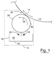
- Fig. 1 shows schematically the structure of a developer unit 10, which is arranged close to a photoconductor drum 12, the photoconductor drum 12 in the direction of an arrow 14 turns.
- a latent charge image which is represented by a not shown Exposure device was applied.
- the latent Charge image are the charges according to the image information of the distributed to print image.
- the drive device for the photoconductor drum 12 has been simplified in FIG. 1 not shown in the illustration.
- the developer unit 10 contains a container 16 in which there is a toner-air mixture 18.
- the mixture 18 are Toner particles and air mixed in a ratio of 1:10, whereby the mixture 18 behaves like a liquid.
- the Mixture 18 is made of solid toner particles with a average size of about 10 microns, whereby by an air permeable bottom plate 20 of the container 16 air flows over a large area into the container 16.
- Two corona devices 22 are arranged in the toner-air mixture 18, each of which has a voltage of approximately -8 kV, so that toner particles of the mixture 18 in the environment the corona devices 22 are negatively charged.
- the corona devices 22 run parallel to each other across the entire developer unit 10 in a length approximately the Expansion of the photoconductor drum 12 transverse to the direction of rotation 14 corresponds.
- a developer roller is located above the corona means 22 24 arranged, the axis of which is parallel to the corona devices 22 runs.
- the developer roller 24 has a potential of about -0.6 kV, so that over the entire length of the corona devices 22 due to the negatively charged toner particles the effect of the electric field between the corona devices 22 and the developer roller 24 on the surface the developer roller 24 are deposited.
- the surface of the developer roller 24 is in one defined distance to the corona devices 22, so that on a uniform toner layer on the surface of the developer roller 24 26 is deposited.
- the developer roller 24 will by a drive device, not shown, in the direction an arrow 28 rotated about its axis.
- a drive device not shown, in the direction an arrow 28 rotated about its axis.
- the toner layer 26 on the periphery of the developer roller 24 transported until it reaches a development nip 30, the through the surface of the photoconductor drum 12 and the Surface of the developer roller 24 is formed, with both surfaces in the area of the development gap 30 e.g. move synchronously.
- the development nip has the axis of the developer roller 24 30 a constant width.
- the latent charge pattern of the Photoconductor drum 12 is developed in the development gap by that in unloaded areas of the surface of the Accumulate photoconductor drum 12 toner particles of the toner layer 26. Toner particles remaining on the developer roller 24 are by a stripper, not shown, of the Surface layer of developer roller 24 removed before again new toner particles in the area of the corona devices 22 are applied.
- the toner image applied to the photoconductor drum 12 becomes transferred to paper at a transfer station, not shown and fixed in a fuser.
- the control device 50 is connected via a line 52 a target toner charge, which e.g. to a specific one Surface portion of the toner layer 26 relates. about a line 54 is the control device 50 a target toner mass for the surface portion of the toner layer 26 as a target value given.
- the control device 50 continues to receive Via a line 56 signals from an optical sensor unit 58, which has a light transmitter, a light receiver and a Evaluation unit contains. The one emitted by the light transmitter Light is remitted from the toner layer 26 to the receiver.
- the actual toner mass per surface section in the toner layer 26 determines. Via line 56 the instantaneous value of the actual toner mass to the control device 50, in the difference in a subtractor 60 from the target toner mass and actual toner mass is formed, wherein at the exit of the Subtractor 60 is a toner mass error signal.
- sensor unit 58 can also be a capacitive sensor contain.
- Developer roller 24 is also a potential sensor unit 62 arranged on the output side via a line 63 the control device 50 is connected.
- the potential sensor unit 62 contains an electrode on which a potential influences that is due to the potential of the developer roller 24 and determined by the totality of the toner charge, which are in the field area of the electrode on the surface of the Developer roller 24 is located.
- the sensor unit 62 contains furthermore an evaluation unit which was influenced by the Potential determines the actual toner charge.
- a subtractor 64 which is contained in the control device 50 is the difference between the target toner charge and the actual toner charge educated. Is at the output of the subtractor 64 a toner charge error signal.
- the two error signals of the subtractors 60 and 64 are fed to a controller 66 which e.g. contains two PI controllers, one of which is on an output line 68 of the control device 50 a control voltage depending on the toner mass error signal USTELL1 generates that on a controlled power supply 70 is present.
- the controlled power supply 70 generates at its output a voltage U3 representing the potential on the corona devices 22 determined.
- the voltage U3 is dependent on the Control voltage USTELL1 set.
- a first control loop I thus contains the optical sensor unit 58, the control device 50, the power supply 70 and the corona devices 22.
- control loop I regulates the toner mass per surface section of layer 26, by the too low toner mass per surface section Potential of the corona devices 22 is increased so that more toner particles on the surface of the developer roller 24 separate. Is the actual toner mass above the value by the target toner mass is specified, the potential of the Corona devices 22 reduced. The result is that less toner particles on the surface of the developer roller 24 deposit.
- the control loop I the actual toner mass per surface section according to the given To keep the target toner mass constant for each surface section.
- the second PI controller contained in controller 66 generates dependent from the toner charge error signal of subtractor 64 on one Line 72 a control voltage USTELL2, which is connected to a controlled Power supply 74 is applied. Depending on the value of the control voltage USTELL2 becomes a voltage at the output of the power supply 74 U1 generated, which affects the charge behavior of a corotron 76.
- the second PI controller outputs the control voltage USTELL2 so that the error signal of the subtractor 64 is absolute is reduced and finally the numerical value "0" until disturbances lead to a new control process.
- On second control loop II thus contains the potential sensor unit 62, the control device 50, the power supply 74 and the corotron 76.
- the voltage Ul is increased, see above that the charge behavior of the corotron 76 also increases. If the actual toner charge per surface section exceeds Layer 26 the predetermined target value, the voltage U1 reduced in size, so that the corotron 76 has fewer charges can be applied to the toner layer 26. Through the control loop II succeeds in the actual toner charge per surface section according to the specified target toner charge per surface section to keep constant during the development process.
- the control device 50 is given a mass-related target toner charge instead of the target toner charge per surface section and the target toner mass per surface section.
- the predetermined mass-related target toner charge is compared with a mass-related actual toner charge, which is determined from the actual toner charge and the actual toner mass using the formula given above.
- a predetermined control strategy of the control device 50 ultimately keeps the mass-related toner charge qT on the layer 26 constant during the development process.
- FIG. 3 shows the developer unit 10, with a control device 50 'the mass-related toner charge of the toner on the Layer 26 regulates with the help of a scorotron 100.
- the control device 50 ' is like the control device 50 (see FIG. 2) constructed, but contains a controller instead of the controller 66 66 '.
- the scorotron 100 will replace the corotron 76 (see Fig. 2) used and additionally contains a control grid 102, to which a voltage U2 is present.
- the voltage U2 is controlled by a controlled power supply 104 Input voltage USTELL3 generated.
- On corona wires of the scorotron 100 lies like the corotron 76 (see FIG. 2) the voltage U1.
- the voltage Ul is preferably one of DC voltage superimposed on an AC voltage.
- the Control device 50 To regulate the toner charge per surface section, the Control device 50 'output a control voltage USTELL3, which are supplied with a line 106 to the input of the power supply 104 becomes.
- the power supply 104 and the control grid 102 are Components of the above-mentioned control circuit II.
- the control voltage USTELL3 is thus selected so that the actual toner charge per surface section on the by the target toner charge adjusts the specified value for each area section.
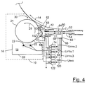
- control device 50 ′′ when regulating the mass-related toner charge the potential of the surface of the developer roller 24 is taken into account.
- the control device 50 ′′ is essentially like the control device 50 '(see FIG. 3). Instead of of controller 66 ', however, it contains a controller 66' 'which when regulating also the current potential of the developer roller 24 considered. This potential is e.g. from the contrast value derived by an operator of the printer entered Has.
- the control device 50 ′′ is connected to a via a line 120 controlled power supply unit 122, being connected on line 120 a bias signal is transmitted.
- a bias signal is transmitted.
- a voltage U4 is generated in the power supply unit 122 via line 124 on the conductive surface of the developer roller 24 is created.
- the selected value of the Potential on the developer roller 24 affects both the Control loop I as well as control loop II, since it has the value of Target toner charge and the target toner mass determined.
Landscapes
- Physics & Mathematics (AREA)
- General Physics & Mathematics (AREA)
- Control Or Security For Electrophotography (AREA)
- Dry Development In Electrophotography (AREA)
- Electrostatic Charge, Transfer And Separation In Electrography (AREA)
- Developing For Electrophotography (AREA)
Description
- Fig. 1
- eine Prinzipdarstellung einer Entwicklereinheit mit einer Entwicklerwalze,
- Fig. 2
- eine Entwicklereinheit mit einer Regeleinrichtung zum Regeln der massebezogenen Tonerladung,
- Fig. 3
- eine Entwicklereinheit mit einer Regeleinrichtung zum Regeln der massebezogenen Tonerladung mit Hilfe eines Skorotrons, und
- Fig. 4
- eine Entwicklereinheit mit einer Regeleinrichtung zum Regeln der massebezogenen Tonerladung unter Berücksichtigung der elektrischen Spannung in einem Entwicklungs-Spalt.
- 10
- Entwicklereinheit
- 12
- Fotoleitertrommel
- 14
- Pfeil
- 16
- Behälter
- 18
- Toner-Luft-Gemisch
- 20
- Bodenplatte
- 22
- Koronaeinrichtung
- 24
- Entwicklerwalze
- 26
- Tonerschicht
- 28
- Pfeil
- 30
- Entwicklungs-Spalt
- 50,50',50''
- Regeleinrichtung
- 52 bis 56
- Leitung
- 58
- optische Sensoreinheit
- 60
- Subtrahierer
- 62
- Potential-Sensoreinheit
- 63
- Leitung
- 64
- Subtrahierer
- 66, 66', 66''
- Regler
- 68
- Ausgangsleitung
- 70
- gesteuertes Netzteil
- 72
- Leitung
- 74
- gesteuertes Netzteil
- 76
- Korotron
- 100
- Skorotron
- 102
- Steuergitter
- 104
- gesteuertes Netzteil
- 106
- Leitung
- 120
- Leitung
- 122
- gesteuertes Netzteil
- 124
- Leitung
- USTELL1
- Stellspannung
- USTELL2
- Stellspannung
- USTELL3
- Stellspannung
- I, II
- Regelkreis
- qT
- massebezogene Tonerladung
- QT
- Tonerladung je Flächenabschnitt
- MT
- Tonermasse je Flächenabschnitt
Claims (7)
- Verfahren zum Betreiben eines elektrografischen Druckers oder Kopierers,dadurch gekennzeichnet, daß in einem zweiten Regelkreis (62, 50, 74, 76) die Ladung der Tonerteilchen der Schicht abhängig von der Abweichung der Ist-Tonerladung von einer vorgegebenen Soll-Tonerladung mit Hilfe einer Aufladevorrichtung, geändert wird.bei dem eine Tonerteilchen enthaltende Schicht (26) auf einer Toneraufnahmefläche (24) unter Wirkung eines Kraftfeldes abgeschieden wird,an mindestens einer Stelle der Schicht (26) die Ist-Tonermasse je Flächenabschnitt erfaßt wird,in einem ersten Regelkreis (58, 50, 70, 22) das Kraftfeld abhängig von der Abweichung der Ist-Tonermasse von einer vorgegebenen Soll-Tonermasse geändert wird,und bei dem an mindestens einer Stelle der Schicht (26) die Ist-Tonerladung je Flächenabschnitt erfaßt wird,
- Verfahren nach Anspruch 1, dadurch gekennzeichnet, daß die Soll-Tonerladung über dem Wert der Tonerladung der Schicht unmittelbar nach dem Aufbringen der Tonerteilchen liegt.
- Verfahren nach einem der vorhergehenden Ansprüche, dadurch gekennzeichnet, daß bei der Vorgabe der Soll-Tonermasse und/oder der Soll-Tonerladung die Spannung in einem Entwicklungs-Spalt (30) berücksichtigt wird, in welchem die Tonerteilchen von der Toneraufnahmefläche (24) auf einen Tonerbildträger (12) übertragen werden.
- Entwicklereinheit (10) für einen elektrografischen Drukker oder Kopierer,mit einer Toneraufnahmefläche (24) zum Aufnehmen einer Tonerteilchen enthaltenden Schicht (26),einer Felderzeugungseinrichtung (22, 70) zum Erzeugen eines Kraftfelds, mit welchem die Tonerteilchen auf der Toneraufnahmefläche (24) abgeschieden werden,mindestens einer Sensoreinheit (58) zum Erfassen der Ist-Tonermasse je Flächenabschnitt der Schicht (26),einer ersten Regeleinrichtung (58, 50, 70, 22), die abhängig von der Abweichung der Ist-Tonermasse von einer vorgegebenen Soll-Tonermasse die Stärke des Kraftfelds ändert,und mit mindestens einer Sensoreinheit (62) zum Erfassen der Ist-Tonerladung je Flächenabschnitt der Schicht (26), gekennzeichnet durch mindestens eine nahe der Toneraufnahmefläche (24) angeordneten Aufladevorrichtung (76) zum Aufladen der Tonerteilchen auf der Toneraufnahmefläche (24),und durch eine zweite Regeleinrichtung (62, 50, 74, 76), die abhängig von der Abweichung der Ist-Tonerladung von einer vorgegebenen Soll-Tonerladung das Ladungsverhalten der Aufladevorrichtung (76) ändert.
- Entwicklereinheit (10) nach Anspruch 4, dadurch gekennzeichnet, daß die Aufladevorrichtung ein Korotron (76) oder ein Skorotron (100) ist, das vorzugsweise mit einer von einer Wechselspannung überlagerten Gleichspannung betrieben wird.
- Entwicklereinheit (10) nach Anspruch 4 oder 5, dadurch gekennzeichnet, daß die Toneraufnahmefläche (24) elektrisch leitend ist und ein Bias-Potential hat, welches bei der Vorgabe der Soll-Tonermasse und/oder der Soll-Tonerladung berücksichtigt wird.
- Vorrichtung zum Drucken oder Kopieren, mit einer Entwicklereinheit (10) nach einem der Ansprüche 4 bis 6.
Applications Claiming Priority (3)
| Application Number | Priority Date | Filing Date | Title |
|---|---|---|---|
| DE19652851 | 1996-12-18 | ||
| DE19652851 | 1996-12-18 | ||
| PCT/DE1997/002977 WO1998027470A1 (de) | 1996-12-18 | 1997-12-18 | Regelung des entwicklungsprozesses eines elektrografischen druckers oder kopierers sowie eine entwicklungseinheit für eine solche regelung |
Publications (2)
| Publication Number | Publication Date |
|---|---|
| EP0946904A1 EP0946904A1 (de) | 1999-10-06 |
| EP0946904B1 true EP0946904B1 (de) | 2000-08-30 |
Family
ID=7815250
Family Applications (1)
| Application Number | Title | Priority Date | Filing Date |
|---|---|---|---|
| EP97952744A Expired - Lifetime EP0946904B1 (de) | 1996-12-18 | 1997-12-18 | Regelung des entwicklungsprozesses eines elektrografischen druckers oder kopierers sowie eine entwicklungseinheit für eine solche regelung |
Country Status (5)
| Country | Link |
|---|---|
| US (1) | US6175697B1 (de) |
| EP (1) | EP0946904B1 (de) |
| JP (1) | JP2001506374A (de) |
| DE (1) | DE59702298D1 (de) |
| WO (1) | WO1998027470A1 (de) |
Families Citing this family (3)
| Publication number | Priority date | Publication date | Assignee | Title |
|---|---|---|---|---|
| US6360067B1 (en) * | 2000-11-28 | 2002-03-19 | Xerox Corporation | Electrophotographic development system with induction charged toner |
| US6353723B1 (en) * | 2000-11-28 | 2002-03-05 | Xerox Corporation | Electrophotographic development system with induction charged toner |
| JP3817496B2 (ja) * | 2002-05-21 | 2006-09-06 | キヤノン株式会社 | 現像装置、プロセスカートリッジ及び画像形成装置 |
Family Cites Families (8)
| Publication number | Priority date | Publication date | Assignee | Title |
|---|---|---|---|---|
| JPS5521070A (en) * | 1978-08-02 | 1980-02-14 | Toshiba Corp | Toner density control device in dry type developing apparatus |
| US4777106A (en) | 1987-02-24 | 1988-10-11 | Dennison Manufacturing Company | Electrostatic toning |
| US5532100A (en) | 1991-01-09 | 1996-07-02 | Moore Business Forms, Inc. | Multi-roller electrostatic toning |
| JPH04238366A (ja) * | 1991-01-22 | 1992-08-26 | Fuji Xerox Co Ltd | 画像記録装置における出力濃度制御方式 |
| JPH052305A (ja) * | 1991-06-26 | 1993-01-08 | Toshiba Corp | 画像形成装置 |
| IL107217A (en) * | 1993-10-08 | 2004-05-12 | Hewlett Packard Indigo Bv | Development control system |
| US5235385A (en) * | 1992-04-15 | 1993-08-10 | Eastman Kodak Company | Method and apparatus for controlling toner image density |
| US5212522A (en) * | 1992-06-29 | 1993-05-18 | Xerox Corporation | Basic developability control in single component development system |
-
1997
- 1997-12-18 DE DE59702298T patent/DE59702298D1/de not_active Expired - Fee Related
- 1997-12-18 EP EP97952744A patent/EP0946904B1/de not_active Expired - Lifetime
- 1997-12-18 US US09/319,327 patent/US6175697B1/en not_active Expired - Fee Related
- 1997-12-18 WO PCT/DE1997/002977 patent/WO1998027470A1/de not_active Ceased
- 1997-12-18 JP JP52719898A patent/JP2001506374A/ja not_active Ceased
Also Published As
| Publication number | Publication date |
|---|---|
| US6175697B1 (en) | 2001-01-16 |
| DE59702298D1 (de) | 2000-10-05 |
| JP2001506374A (ja) | 2001-05-15 |
| WO1998027470A1 (de) | 1998-06-25 |
| EP0946904A1 (de) | 1999-10-06 |
Similar Documents
| Publication | Publication Date | Title |
|---|---|---|
| DE2055321C3 (de) | Gerät zum Zuführen eines Toners in einer elektrophotographischen Kopiervorrichtung | |
| DE3851722T2 (de) | Bilderzeugungsgerät. | |
| DE19731251B4 (de) | Bilderzeugungseinrichtung und Entwicklungsverfahren für eine Bilderzeugungseinrichtung | |
| EP0403523B1 (de) | Elektrofotografische druckeinrichtung mit geregeltem elektrofotografischen prozess | |
| DE2747014B2 (de) | Elektrophotographische Entwicklungsvorrichtung | |
| DE3512060A1 (de) | Bilderzeugungsgeraet | |
| DE60002416T2 (de) | Bilderzeugungsverfahren und Vorrichtung zur effektiven Bilddichtesteuerung | |
| DE3840712A1 (de) | Vorrichtung zum entwickeln eines auf einem photorezeptor erzeugten latentbilds | |
| DE19631261A1 (de) | Vorrichtung und Verfahren zur Regelung der Schwärzung und zum Verlängern der Lebensdauer des Entwicklers durch langfristiges Abstimmen der Tonerkonzentration | |
| DE3034947A1 (de) | Tonerkonzentration-regelungssystem | |
| DE69217304T2 (de) | Auswechselbare Einzelteile für elektrostatografische Kopiermaschinen | |
| DE69511132T2 (de) | Verfahren und System zum Steuern der Tonerkonzentration | |
| DE69820136T2 (de) | Nachweis für toneraufbrauch in einem adaptiven elektrophotographischen drucksystem | |
| DE4210077A1 (de) | Bilderzeugungseinrichtung | |
| DE3728493C2 (de) | ||
| WO1999036834A1 (de) | Einrichtung und verfahren zum drucken oder kopieren, wobei eine tonermarke an mindestens zwei messorten abgetastet wird | |
| EP0946904B1 (de) | Regelung des entwicklungsprozesses eines elektrografischen druckers oder kopierers sowie eine entwicklungseinheit für eine solche regelung | |
| EP1141787B1 (de) | Verfahren und einrichtung zur regelung der tonerkonzentration in einem elektrografischen prozess | |
| DE3906885C2 (de) | ||
| EP1525514B1 (de) | Verfahren und vorrichtung zum einstellen der tonerkonzentration in der entwicklerstation eines elektrofotografischen druckers oder kopierers | |
| EP0946905B1 (de) | Entwicklereinheit für einen elektrografischen drucker oder kopierer | |
| DE3837528C2 (de) | Elektrofotografisches Kopiergerät | |
| EP0946906B1 (de) | Verfahren zum betreiben eines elektrografischen druckers oder kopierers | |
| DE4232232C2 (de) | Verfahren und Einrichtung zur Aufbringung von Toner-Bildern auf ein lichtempfindliches Medium | |
| DE19507290C2 (de) | Elektrophotographisches Gerät mit Entwicklungseinheit |
Legal Events
| Date | Code | Title | Description |
|---|---|---|---|
| PUAI | Public reference made under article 153(3) epc to a published international application that has entered the european phase |
Free format text: ORIGINAL CODE: 0009012 |
|
| 17P | Request for examination filed |
Effective date: 19990715 |
|
| AK | Designated contracting states |
Kind code of ref document: A1 Designated state(s): BE DE FR GB |
|
| GRAG | Despatch of communication of intention to grant |
Free format text: ORIGINAL CODE: EPIDOS AGRA |
|
| 17Q | First examination report despatched |
Effective date: 19991027 |
|
| GRAG | Despatch of communication of intention to grant |
Free format text: ORIGINAL CODE: EPIDOS AGRA |
|
| GRAH | Despatch of communication of intention to grant a patent |
Free format text: ORIGINAL CODE: EPIDOS IGRA |
|
| GRAH | Despatch of communication of intention to grant a patent |
Free format text: ORIGINAL CODE: EPIDOS IGRA |
|
| GRAA | (expected) grant |
Free format text: ORIGINAL CODE: 0009210 |
|
| AK | Designated contracting states |
Kind code of ref document: B1 Designated state(s): BE DE FR GB |
|
| REF | Corresponds to: |
Ref document number: 59702298 Country of ref document: DE Date of ref document: 20001005 |
|
| GBT | Gb: translation of ep patent filed (gb section 77(6)(a)/1977) |
Effective date: 20001101 |
|
| ET | Fr: translation filed | ||
| PLBE | No opposition filed within time limit |
Free format text: ORIGINAL CODE: 0009261 |
|
| STAA | Information on the status of an ep patent application or granted ep patent |
Free format text: STATUS: NO OPPOSITION FILED WITHIN TIME LIMIT |
|
| 26N | No opposition filed | ||
| REG | Reference to a national code |
Ref country code: GB Ref legal event code: IF02 |
|
| PGFP | Annual fee paid to national office [announced via postgrant information from national office to epo] |
Ref country code: BE Payment date: 20071128 Year of fee payment: 11 |
|
| PGFP | Annual fee paid to national office [announced via postgrant information from national office to epo] |
Ref country code: GB Payment date: 20071219 Year of fee payment: 11 |
|
| PGFP | Annual fee paid to national office [announced via postgrant information from national office to epo] |
Ref country code: DE Payment date: 20080131 Year of fee payment: 11 |
|
| PGFP | Annual fee paid to national office [announced via postgrant information from national office to epo] |
Ref country code: FR Payment date: 20071214 Year of fee payment: 11 |
|
| BERE | Be: lapsed |
Owner name: *OCE PRINTING SYSTEMS G.M.B.H. Effective date: 20081231 |
|
| GBPC | Gb: european patent ceased through non-payment of renewal fee |
Effective date: 20081218 |
|
| PG25 | Lapsed in a contracting state [announced via postgrant information from national office to epo] |
Ref country code: BE Free format text: LAPSE BECAUSE OF NON-PAYMENT OF DUE FEES Effective date: 20081231 |
|
| REG | Reference to a national code |
Ref country code: FR Ref legal event code: ST Effective date: 20090831 |
|
| PG25 | Lapsed in a contracting state [announced via postgrant information from national office to epo] |
Ref country code: DE Free format text: LAPSE BECAUSE OF NON-PAYMENT OF DUE FEES Effective date: 20090701 |
|
| PG25 | Lapsed in a contracting state [announced via postgrant information from national office to epo] |
Ref country code: GB Free format text: LAPSE BECAUSE OF NON-PAYMENT OF DUE FEES Effective date: 20081218 |
|
| PG25 | Lapsed in a contracting state [announced via postgrant information from national office to epo] |
Ref country code: FR Free format text: LAPSE BECAUSE OF NON-PAYMENT OF DUE FEES Effective date: 20081231 |