EP0945742B1 - Linsenrasterplatte und diese verwendender transmissionsschirm - Google Patents
Linsenrasterplatte und diese verwendender transmissionsschirm Download PDFInfo
- Publication number
- EP0945742B1 EP0945742B1 EP98941817A EP98941817A EP0945742B1 EP 0945742 B1 EP0945742 B1 EP 0945742B1 EP 98941817 A EP98941817 A EP 98941817A EP 98941817 A EP98941817 A EP 98941817A EP 0945742 B1 EP0945742 B1 EP 0945742B1
- Authority
- EP
- European Patent Office
- Prior art keywords
- light
- entering
- lens sheet
- lenticular lens
- emerging
- Prior art date
- Legal status (The legal status is an assumption and is not a legal conclusion. Google has not performed a legal analysis and makes no representation as to the accuracy of the status listed.)
- Expired - Lifetime
Links
Images


Classifications
-
- G—PHYSICS
- G02—OPTICS
- G02B—OPTICAL ELEMENTS, SYSTEMS OR APPARATUS
- G02B3/00—Simple or compound lenses
- G02B3/0006—Arrays
- G02B3/0037—Arrays characterized by the distribution or form of lenses
- G02B3/005—Arrays characterized by the distribution or form of lenses arranged along a single direction only, e.g. lenticular sheets
-
- G—PHYSICS
- G02—OPTICS
- G02B—OPTICAL ELEMENTS, SYSTEMS OR APPARATUS
- G02B3/00—Simple or compound lenses
- G02B3/0006—Arrays
- G02B3/0037—Arrays characterized by the distribution or form of lenses
- G02B3/0062—Stacked lens arrays, i.e. refractive surfaces arranged in at least two planes, without structurally separate optical elements in-between
- G02B3/0068—Stacked lens arrays, i.e. refractive surfaces arranged in at least two planes, without structurally separate optical elements in-between arranged in a single integral body or plate, e.g. laminates or hybrid structures with other optical elements
-
- G—PHYSICS
- G03—PHOTOGRAPHY; CINEMATOGRAPHY; ANALOGOUS TECHNIQUES USING WAVES OTHER THAN OPTICAL WAVES; ELECTROGRAPHY; HOLOGRAPHY
- G03B—APPARATUS OR ARRANGEMENTS FOR TAKING PHOTOGRAPHS OR FOR PROJECTING OR VIEWING THEM; APPARATUS OR ARRANGEMENTS EMPLOYING ANALOGOUS TECHNIQUES USING WAVES OTHER THAN OPTICAL WAVES; ACCESSORIES THEREFOR
- G03B21/00—Projectors or projection-type viewers; Accessories therefor
- G03B21/54—Accessories
- G03B21/56—Projection screens
- G03B21/60—Projection screens characterised by the nature of the surface
- G03B21/62—Translucent screens
- G03B21/625—Lenticular translucent screens
Definitions
- the present invention relates to a lenticular lens sheet suitable for projecting thereon an image from an imaging light source having a cellular structure such as an LCD (Liquid Crystal Display) or DMD (Digital Micromirror Device), and to a rear projection screen using the same.
- an imaging light source having a cellular structure such as an LCD (Liquid Crystal Display) or DMD (Digital Micromirror Device)
- LCD Liquid Crystal Display
- DMD Digital Micromirror Device
- rear projection type televisions comprising an imaging light source consisting of three CRTs (Cathode Ray Tubes) of red, green and blue, and a rear projection screen.
- CRTs Cathode Ray Tubes
- a combination of a Fresnel lens sheet for making rays projected from the CRTs almost parallel with each other, and a light-diffusing sheet for diffusing light over a wide range is used as the rear projection screen.
- the light-diffusing sheet is a lenticular lens sheet in which lens elements (light-entering lenses) for condensing light such as lenticular lenses are formed on the light-entering side, and a light-emerging face is formed in the vicinity of the focal points of these light-entering lenses.
- a light-absorbing layer (black stripe) is provided on the light-emerging face of the lenticular lens sheet, between the focal points of the light-entering lenses, so that light can be diffused and that the effects of extraneous light can be reduced.
- the pitch of the lenticular lens is made as small as 1/3.5 or less of the grating constant of the grating pattern projected. Further, in those projection televisions using an LCD, DMD or the like, the glaring of an image called scintillation occurs. To make the pitch of the lenticular lens small is also effective for attenuating this scintillation.
- the pitch of the lenticular lens is made 0.4 mm or less, and the thickness of the lenticular lens sheet, which corresponds to the distance between the lenticular lenses and the light-emerging face, is made 0.52 mm or less.
- US-A-3 830 556 which forms the preamble of the independent claim 1, discloses a rear projection screen having a lens formation on at least one side thereof, the lens formation forming an array of individual lenses distributed over the screen.
- each of said lenses comprises a plurality of lens surface portions, each lens surface portion having a shape individually determined in accordance with the corresponding portion of a desired light intensity distribution patent.
- the rigidity is decreased, so that it becomes difficult to maintain the lenticular lens sheet flat Further, it is quite difficult to form a thin lenticular lens sheet by means of extrusion molding or the like with high accuracy.
- the power of a light source using an LCD, DMD or the like is not so high as that of a light source using three CRTs of red, green and blue, and the contrast is also poor. Therefore, those rear projection screens which are used in combination with an LCD, DMD or the like are demanded to have high contrast as compared with the conventional rear projection screens which are used along with CRTs.
- the most effective method for improving the contrast of a rear projection screen using a lenticular lens sheet is to increase the ratio of a total area of light-absorbing layers (black stripes) to area of light-emerging face of the screen (black stripe ratio).
- An object of the present invention is to provide a lenticular lens sheet and a rear projection screen using the lenticular lens sheet, in which the thickness of a lenticular lens can be increased while keeping its pitch fine, and the black stripe ratio can also be increased.
- a lenticular lens sheet comprising:
- a lenticular lens sheet comprising a light-entering lens part formed on the light-entering surface, in which a plurality of light-entering lenses, each having a substantially elliptical cross section are arranged, a light-emerging lens part formed on the light-emerging surface, in which a plurality of light-emerging lenses, each having a concave-lens-like cross section are arranged so that they correspond to the condensing positions of the respective light-entering lenses in the light-entering lens part, and a plurality of light-absorbing layers formed on the light-emerging surface, arranged so that they correspond to the non-condensing positions of the respective light-entering lenses in the light-entering lens part.
- a rear projection screen for use in a rear projection type television, comprising a Fresnel lens sheet for making projected rays almost parallel with each other, and a lenticular lens sheet according to the invention arranged on the light-emerging of the Fresnel lens sheet, wherein the lenticular lens sheet comprises a light-entering lens part formed on the light-entering surface, in which a plurality of light-entering lenses, each having a substantially elliptical cross section are arranged, and a light-emerging lens part formed on the light-emerging surface, in which a plurality of light-emerging lenses, each having a concave-lens-like cross section are arranged so that they correspond to the condensing positions of the respective light-entering lenses in the light-entering lens part, wherein condensing positions of the light-entering lenses are inside the lenticular lens sheet.
- a rear projection screen for use in a rear projection type television, comprising a Fresnel lens sheet for making projected rays almost parallel with each other, and a lenticular lens sheet arranged on the light-emerging of the Fresnel lens sheet, wherein the lenticular lens sheet comprises a light-entering lens part formed on the light-entering surface, in which a plurality of light-entering lenses, each having a substantially elliptical cross section are arranged, a light-emerging lens part formed on the light-emerging surface, in which a plurality of light-emerging lenses, each having a concave-lens-like cross section are arranged so that they correspond to the condensing positions of the respective light-entering lenses in the light-entering lens part, and a plurality of light-absorbing layers formed on the light-emerging surface, arranged so that they correspond to the non-condensing positions of the respective light-entering lenses in the light-
- a protruded portion having a substantially trapezoidal cross section be formed on the light-emerging surface, at a position corresponding to the non-condensing position of each one of the above-described light-entering lenses in the above-described lighten-entering lens part and that the above-described light-absorbing layers be formed on the top faces of these protruded portions.
- the light-absorbing layers be also formed on the inclined faces, in addition to the top faces, of the protruded portions.
- the light-emerging lenses in the light-emerging lens part are made in the shape of a concave lens, it is possible to make the thickness to pitch of the lenticular lens sheet great, and thus to reduce the production of a moiré pattern while maintaining the mechanical strength.
- protruded portions each having a substantially trapezoidal cross section, on the light-emerging surface, at those positions which correspond to the non-condensing positions of the respective light-entering lenses in the light-entering lens part, it is possible to effectively prevent the protruded portions from being exposed to light emerged from the light-emerging lenses. Therefore, light from a light source can effectively be utilized even when an LCD or DMD whose power is lower than that of a CRT is used.
- light-absorbing layers also on the inclined faces, in addition to the top faces, of the protruded portions, it is possible to increase the black stripe ratio on the light-emerging surface.
- Figs. 1 and 2 are views showing a first embodiment of the lenticular lens sheet according to the present invention.
- a lenticular lens sheet 10A comprises, on the light-entering surface thereof, a light-entering lens part in which a plurality of light-entering lenses 11 are formed, and, on the light-emerging surface, a light-emerging lens part in which a plurality of light-emerging lenses 12 are formed, wherein the light-emerging lenses 12 are arranged so that they respectively correspond to the condensing positions of the light-entering lenses 11.
- a protruded portion 13A having an almost rectangular cross section is provided on the light-emerging surface, at a position corresponding to the non-condensing position of each one of the light-entering lenses 11, and a black stripe (light-absorbing layer) 14 is provided on the top face 13a of this protruded portion 13A by the application of a light-absorbing agent
- a diffusing agent such as glass beads or acrylic beads may entirely be incorporated into the lenticular lens sheet 10A.
- the light-entering lens 11 is in the shape of a convex lens projecting toward the light-entering side, and so designed that its condensing point (condensing position) will be inside the lenticular lens sheet 10A.
- the light-emerging lens 12 is in the shape of a concave lens projecting toward the inside of the lenticular lens sheet 10A.
- Substantially elliptical such as circular, elliptical and aspherical shapes can be used as the shape of the cross section of the light-entering lens 11.
- concave-lens-like shapes such as concave circle, concave ellipse, concave hyperbola and concave parabola can be used as the shape of the cross section of the light-emerging lens 12.
- the light-emerging lens 12 when the light-emerging lens 12 is made in the shape of a concave lens, it is proper that the light-entering lens 11 be made in a shape represented by the following equation (1).
- the conical coefficient k in the equation (1) fall in the range -0.35 ⁇ k ⁇ -0.1, preferably in the range -0.3 ⁇ k ⁇ -0.2.
- the value of the constant c in consideration of the relationship between the thickness and diffusion angle of the lenticular lens sheet It is herein preferable to make the value of p/ 2c fall in the range of 0.8 to 1.0 (when the value of p/2c is too large, it is necessary to make the thickness small; on the contrary, when this value is too small, the angle of diffusion cannot be obtained).
- y x 2 / c 1 + 1 - ( k + 1)( x / c ) 2
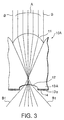
- Fig. 3 is a view showing the optical path of imaging light in the lenticular lens sheet 10A shown in Figs. 1 and 2.
- light A which has entered the light-entering lens 11 from the vicinity of the center thereof forms a condensing point in the vicinity of the light-emerging lens 12.
- light B which has entered the light-entering lens 11 from the periphery thereof forms a condensing point at the inner part of the light-emerging lens 12, and is refracted by the light-emerging lens 12 toward the outside of the light A refracted (see the symbol B 1 in Fig. 3).
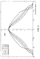
- Fig. 4 is a graph showing the distribution of gains of the lenticular lens sheet 10A shown in Figs. 1 and 2.
- regarded as important are to ensure approximately 30° as the deviation angle (horizontal half angle ( ⁇ H)) at which the gain is 1 / 2 of the central gain (the gain when the deviation angle is 0°), and to make both the central gain and the gain when the deviation angle is not less than 50° sufficiently high.
- the light-emerging lens 12 is made in the shape of a concave lens, the thickness t to the pitch p of the lenticular lens sheet 10A can be made great. It is therefore possible to reduce the production of a moiré pattern while maintaining the mechanical strength.
- Fig. 5 is a view showing a second embodiment of the lenticular lens sheet according to the present invention. It is noted that, in the second embodiment of the present invention, those parts which have the same functions as in the above-described first embodiment are indicated by the same symbols, and detailed descriptions for these parts are suitably omitted.
- a protruded portion 13B having a substantially trapezoidal cross section is formed on the light-emerging surface, at a position corresponding to the non-condensing position of each one of the light-entering lenses 11, and a black stripe (light-absorbing layer) 14 is formed on both the top face 13a and inclined face 13b of this protruded portion 13B by applying thereto a light-absorbing agent. It is preferable that the ratio of the black stripes 14 (black stripe rate) on the light-emerging surface be 60% or more.
- a diffusing layer 15 for diffusing light which has entered through the light-entering lenses 11 may be formed in the lenticular lens sheet 10B.
- the above-described protruded portions 13B are formed on the light-emerging surface of the diffusing layer 15.
- the diffusing layer 15 can be formed, for example, by incorporating a diffusing agent such as glass beads or acrylic beads.
- the cross section of the protruded portion 13B is made substantially trapezoidal, it is possible to effectively prevent the protruded portions 13B from being exposed to light emerged from the light-emerging lenses 12 as compared with the case where the cross section of the protruded portion 13A is made substantially rectangular as in the above-described first embodiment. For this reason, light from a light source can effectively be utilized even when an LCD or DMD whose power is lower than that of a CRT is used.
- black stripes 14 are also formed on the inclined faces 13b, in addition to the top faces 13a, of the protruded portions 13B, each having a substantially trapezoidal cross section, so that it is possible to make the black stripe rate on the light-emerging surface high as compared with the above-described first embodiment.
- Fig. 6 is a view showing a third embodiment of the lenticular lens sheet according to the present invention. It is noted that, in the third embodiment of the present invention, those parts which have the same functions as in the above-described first embodiment are indicated by the same symbols, and detailed descriptions for these parts are suitably omitted.
- a diffusing layer 15 for diffusing light which has entered through light-entering lenses 11 is formed by incorporating a diffusing agent such as glass beads or acrylic beads, and a protruded portion 13B having a substantially trapezoidal cross section is formed on the light-emerging surface of this diffusing layer 15, at a position corresponding to the non-condensing position of each one of the light-entering lenses 11. Further, a non-diffusing layer 16 containing no diffusing agent is entirely formed on the light-emerging surface of the diffusing layer 15, including the protruded portions 13B.
- the non-diffusing layer 16 is entirely formed on the light-emerging surface of the diffusing layer 15, including the protruded portions 13B, it is possible to prevent the uneven application of the light-absorbing agent which is applied to the top faces 13a and inclined faces 13b of the protruded portions 13B to form the black stripes 14. For this reason, it is possible to effectively prevent the lenticular lens sheet from having a rough appearance which is brought about due to the unevenness especially on the inclined faces 13b.
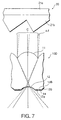
- Fig. 7 is a view showing one embodiment of the rear projection screen according to the present invention.
- a rear projection screen of this embodiment is for use in a rear projection type television, and comprises a Fresnel lens sheet 20 for making projected rays almost parallel with each other, and a lenticular lens sheet 10D arranged on the light-emerging side (observation side) of the Fresnel lens sheet 20. It is noted that this lenticular lens sheet 10D corresponds to a case where the diffusing layer 15 is not formed in the lenticular lens sheet 10B shown in Fig. 2.
- the Fresnel lens sheet 20 is made with a base 21a and a Fresnel lens part 21b, and the light-diffusing element is formed by incorporating a predetermined amount of a diffusing agent into the base 21a.
- the diffusing agent incorporated into the base 21a of the Fresnel lens sheet 20.
- a circular Fresnel lens, a linear Fresnel lens or the like with its lens face facing the observation side is suitably used as the Fresnel lens part 21b.
- the horizontal diffusion properties of light C which enters the lenticular lens sheet 10D can further be broadened due to the diffusing agent incorporated into the base 21a of the Fresnel lens sheet 20, it is possible to reduce scintillation.
- the lenticular lens sheet 10A, 10B or 10C shown in Fig. 1, 5 or 6, respectively can be used as the lenticular lens sheet.
- Example 1 corresponds to the lenticular lens sheet 10A of the above-described first embodiment (see Figs. 1 and 2).
- a resin obtained by incorporating 7.2 parts by weight of acrylic beads having a mean particle diameter of 30 ⁇ m (refractive index 1.49) and 1.2 parts by weight of glass beads having a mean particle diameter of 17 ⁇ m (refractive index 1.535) into 100 parts by weight of an impact-resistant acrylic resin (refractive index 1.51) the lenticular lens sheet 10A was formed by means of extrusion molding as a single
- the protruded portion 13A was formed so that the side (inclined face) thereof would protrude almost vertically (5°), and the black stripe 14 was formed by applying a light-absorbing agent only to the top face 13a of the protruded portion 13A.
- the height of the protruded portion 13A provided with the black stripe 14 was made 0.08 mm, and the black stripe ratio on the light-emerging surface was made 40%.
- the conical coefficient k of the light-entering lens 11 was made -0.1.
- the value of c in the above equation (1) was made 0.212, and the value of p/2c in the same was made 0.85.
- Example 2 corresponds to the lenticular lens sheet 10B of the above-described second embodiment (see Fig. 5).
- the lenticular lens sheet 10B was formed by means of extrusion molding as double layers (a layer of the light-entering lens 11 and the diffusing layer 15).
- 10.8 parts by weight of acrylic beads having a mean particle diameter of 30 ⁇ m (refractive index 1.49), and 1.8 parts by weight of glass beads having a mean particle diameter of 17 ⁇ m (refractive index 1.535) were incorporated into the diffusing layer 15 as diffusing agents.
- the protruded portion 13B was formed so that the side (inclined face 13b) thereof would protrude at an angle of 50°, and the black stripe 14 was formed by applying a light-absorbing agent to both the top face 13a and inclined face 13b of the protruded portion 13B.
- the height of the protruded portion 13B provided with the black stripe 14 was made 0.06 mm, and the black stripe ratio on the light-emerging surface was made 65%.
- the conical coefficient k of the light-entering lens 11 was made -0.3.
- the value of c in the above equation (1) was made 0.1764, and the value of p/2c in the same was made 0.99.
- Example 3 corresponds to the lenticular lens sheet 10C of the above-described third embodiment (see Fig. 6).
- the lenticular lens sheet 10C was formed by means of extrusion molding as three layers (a layer of the light-entering lens 11, the diffusing layer 15 and the non-diffusing layer 16).
- 10.8 parts by weight of acrylic beads having a mean particle diameter of 30 ⁇ m (refractive index 1.49), and 1.8 parts by weight of glass beads having a mean particle diameter of 17 ⁇ m (refractive index 1.535) were incorporated into the diffusing layer 15 as diffusing agents.
- the protruded portion 13B was formed so that the side (inclined face 13b) thereof would protrude at an angle of 50°, and the black stripe 14 was formed by applying a light-absorbing agent to both the top face 13a and inclined face 13b of the protruded portion 13B.
- the height of the protruded portion 13B provided with the black stripe 14 was made 0.06 mm, and the black stripe rate on the light-emerging-side surface was made 65%.
- the conical coefficient k of the light-entering lens 11 was made -0.3.
- the value of c in the above equation (1) was made 0.1764, and the value of p/ 2c in the same was made 0.99.
- the Fresnel lens sheet 20 was made by using, as the base 21a, the above-described impact-resistant acrylic resin (thickness 2.5 mm) into which 2.0 parts by weight of the above-described acrylic beads having a mean particle diameter of 30 ⁇ m (refractive index 1.49) had been incorporated, and forming the Fresnel lens part 21b on top of this base by using an ultraviolet-light-curable resin, by means of a UV production method.
- the conical coefficient k of the light-entering lens 11 is shown in the column “Shape of Light-Entering Lens”. Further, in the column “Shape of Light-Emerging Lens", the shape of the cross section of the light-emerging lens 12 is shown. "-0.2R” in this column means that the shape of the cross section of the light-emerging lens 12 is a part of a circle (circular arc) having a diameter of 0.2 mm, and the symbol minus means that the arc is not convex (plus) but concave.
- the 1/2 luminance angle of the rear projection screen which is a combination of the lenticular lens sheet 10A and the Fresnel lens sheet 20 is nearly 30° ; and with respect to Examples 2 and 3, 35° was able to be ensured as the 1 / 2 luminance angle like in the case of conventional lenticular lens sheets in which the pitch of the light-entering lens 11 is 0.7 mm or more. Moreover, with respect to Examples 2 and 3, a value of nearly 50° was able to be ensured as the 1/10 luminance angle like in the case of conventional lenticular lens sheets.
- the appearances (the degree of roughness) of the lenticular lens sheets 10A, 10B and 10C are shown. As shown in the above Table 1, with respect to Example 2, a slightly rough appearance was observed; on the other hand, with respect to Examples 1 and 3, a good appearance free from roughness was observed.
- the pitch of the light-entering lens 11 is made approximately 0.35 mm in order to make a moiré pattern which is produced on a rear projection screen obscure
- the lenticular lens sheet is made by the use of an acrylic resin, it is possible to prevent the lenticular lens sheet from having decreased rigidity and from being easily broken; and, in addition, it is possible to make the lenticular lens sheet by means of extrusion molding or the like with high accuracy.
Landscapes
- Physics & Mathematics (AREA)
- General Physics & Mathematics (AREA)
- Optics & Photonics (AREA)
- Overhead Projectors And Projection Screens (AREA)
- Optical Elements Other Than Lenses (AREA)
Claims (12)
- Linsenrasterplatte bzw. linsenförmiges Linsenblatt (10A; 10B; 10C; 10D), umfassend:dadurch gekennzeichnet, daßein Lichteintrittslinsenteil, das an einer Lichteintrittsoberfläche ausgebildet ist, in welcher eine Mehrzahl von Lichteintrittslinsen (11) angeordnet ist, undein lichtaustrittsseitiges Linsenteil, das an einer Lichtaustrittsoberfläche ausgebildet ist, in welcher eine Mehrzahl von Lichtaustrittslinsen (12), die jeweils einen konkaven, linsenartigen Querschnitt aufweisen, so angeordnet ist, daß sie einer Sammlungs- bzw. Konzentrationsposition der entsprechenden Lichteintrittslinsen (11) in dem lichteintrittsseitigen Linsenteil entsprechen,
jede der Lichteintrittslinsen (11) einen im wesentlichen elliptischen Querschnitt aufweist, worin Konzentrationspositionen der Lichteintrittslinsen (11) sich innerhalb des linsenförmigen Linsenblatts (10A; 10B; 10C; 10D) befinden. - Linsenförmiges Linsenblatt (10A; 10B; 10C; 10D) nach Anspruch 1, umfassend:eine Mehrzahl von lichtabsorbierenden Schichten (14), die an der Lichtaustrittsoberfläche ausgebildet sind, welche so angeordnet sind, daß sie den nicht konzentrierenden Positionen der entsprechenden Lichteintrittslinsen (11) in dem Lichteintrittslinsenteil entsprechen.
- Linsenförmiges Linsenblatt (10A; 10B; 10C; 10D) nach Anspruch 1 oder 2, worin die Beziehung des Abstands p von jeder der Lichteintrittslinsen (11) in dem lichteintrittsseitigen Linsenteil und der Dicke t des linsenförmigen Linsenblatts 1,3 = t/p ≤ 1,9 ist.
- Linsenförmiges Linsenblatt (10A; 10B; 10C; 10D) nach einem oder mehreren der vorhergehenden Ansprüche, worin der konische Koeffizient k von jeder der Lichteintrittslinsen (11) in dem Lichteintrittslinsenteil in dem Bereich von -0,35 = k ≤ -0,1 liegt.
- Linsenförmiges Linsenblatt (10A; 10B; 10C; 10D) nach einem oder mehreren der vorhergehenden Ansprüche und Anspruch 2, worin ein vorragender Abschnitt (13A; 13B), der einen im wesentlichen rechteckigen oder trapezförmigen Querschnitt aufweist, auf der Lichtaustrittsoberfläche an einer Position entsprechend der nicht konzentrierenden Position von jeder der Lichteintrittslinsen (11) in dem Lichteintrittslinsenteil ausgebildet ist, und die lichtabsorbierenden Schichten (14) an den Oberseiten (13a; 13b) von diesen vorragenden Abschnitten (13A; 13B) ausgebildet sind.
- Linsenförmiges Linsenblatt (10C) nach Anspruch 5, worin eine nicht streuende Schicht (16), enthaltend kein streuendes bzw. Diffusionsmittel, auf der Oberfläche der vorragenden Abschnitte (13A) ausgebildet ist, die einen im wesentlichen rechteckigen Querschnitt aufweisen.
- Linsenförmiges Linsenblatt (10B; 10C; 10D) nach Anspruch 5, worin die lichtabsorbierenden Schichten (14) auch auf den geneigten Seiten bzw. Flächen (13b) zusätzlich zu den Oberseiten (13a) der vorragenden Abschnitte (13B) ausgebildet sind, die einen im wesentlichen trapezförmigen Querschnitt aufweisen.
- Linsenförmiges Linsenblatt (10C) nach Anspruch 7, worin eine nicht streuende Schicht (16), enthaltend kein streuendes bzw. Diffusionsmittel, auf der Oberfläche der vorragenden Abschnitte (13B) ausgebildet sind, die einen im wesentlichen trapezförmigen Querschnitt aufweisen.
- Linsenförmiges Linsenblatt (10A; 10B; 10C; 10D) nach einem oder mehreren der vorhergehenden Ansprüche und Anspruch 2, worin der Anteil der lichtabsorbierenden Schichten (14) an der Lichtaustrittsseite 60 % oder mehr beträgt.
- Rückprojektionsschirm bzw. Durchlichtprojektionsschirm zur Verwendung in einem durchlichtartigen Femseher, umfassend:ein Fresnel-Linsenblatt (20), um projizierte Strahlen nahezu parallel zueinander auszubilden; undein linsenförmiges Linsenblatt bzw. eine Linsenrasterplatte (10A; 10B; 10C; 10D) nach einem der vorhergehenden Ansprüche, das (die) auf der Lichtaustrittsseite des Fresnel-Linsenblatts angeordnet ist.
- Durchlichtprojektionsschirm zur Verwendung in einem durchlichtartigen Femseher nach Anspruch 10, umfassend eine Mehrzahl lichtabsorbierenden Schichten (14), die auf der Lichtaustrittsoberfläche ausgebildet sind, die so angeordnet sind, daß sie den nicht konzentrierenden Positionen der entsprechenden Lichteintrittslinsen (11) in dem Lichteintrittslinsenteil entsprechen.
- Durchlichtprojektionsschirm nach Anspruch 10 oder 11, worin das Fresnel-Linsenblatt (20) ein lichtstreuendes Element aufweist.
Applications Claiming Priority (3)
| Application Number | Priority Date | Filing Date | Title |
|---|---|---|---|
| JP24712197 | 1997-09-11 | ||
| JP24712197A JP3822961B2 (ja) | 1997-09-11 | 1997-09-11 | レンチキュラーレンズシート及び透過型スクリーン |
| PCT/JP1998/004085 WO1999013362A1 (fr) | 1997-09-11 | 1998-09-10 | Feuille a effet de lentille lenticulaire et ecran de transmission utilisant une telle feuille |
Publications (3)
| Publication Number | Publication Date |
|---|---|
| EP0945742A1 EP0945742A1 (de) | 1999-09-29 |
| EP0945742A4 EP0945742A4 (de) | 2001-01-31 |
| EP0945742B1 true EP0945742B1 (de) | 2004-05-26 |
Family
ID=17158755
Family Applications (1)
| Application Number | Title | Priority Date | Filing Date |
|---|---|---|---|
| EP98941817A Expired - Lifetime EP0945742B1 (de) | 1997-09-11 | 1998-09-10 | Linsenrasterplatte und diese verwendender transmissionsschirm |
Country Status (6)
| Country | Link |
|---|---|
| US (1) | US6169633B1 (de) |
| EP (1) | EP0945742B1 (de) |
| JP (1) | JP3822961B2 (de) |
| DE (1) | DE69824140T2 (de) |
| DK (1) | DK0945742T3 (de) |
| WO (1) | WO1999013362A1 (de) |
Families Citing this family (24)
| Publication number | Priority date | Publication date | Assignee | Title |
|---|---|---|---|---|
| US6870681B1 (en) * | 1992-09-21 | 2005-03-22 | University Of Arkansas, N.A. | Directional image transmission sheet and method of making same |
| US6424786B1 (en) | 1996-12-02 | 2002-07-23 | Honeywell International Inc. | Illumination assembly |
| JP3968545B2 (ja) * | 1998-10-28 | 2007-08-29 | セイコーエプソン株式会社 | マイクロレンズアレイの製造方法 |
| WO2001071410A2 (en) * | 2000-03-17 | 2001-09-27 | Zograph, Llc | High acuity lens system |
| US6665118B2 (en) * | 2000-08-30 | 2003-12-16 | Matsushita Electric Industrial Co., Ltd. | Rear-projection screen and rear-projection image display |
| DK1334405T3 (da) * | 2000-11-09 | 2007-05-29 | Dainippon Printing Co Ltd | Linseformet linseplade og projektionsskærm |
| US6443579B1 (en) | 2001-05-02 | 2002-09-03 | Kenneth Myers | Field-of-view controlling arrangements |
| US6726858B2 (en) | 2001-06-13 | 2004-04-27 | Ferro Corporation | Method of forming lenticular sheets |
| JP2003121609A (ja) * | 2001-10-11 | 2003-04-23 | Hitachi Ltd | 光学シートおよびこれを備えた表示装置 |
| WO2004081650A2 (en) * | 2003-03-12 | 2004-09-23 | Avery Dennison Corporation | Rear projection screens and methods of making the same |
| GB2400905A (en) * | 2003-04-24 | 2004-10-27 | Memco Ltd | Edge device for a powered door with infra-red and visible elements |
| US20050226590A1 (en) * | 2004-04-07 | 2005-10-13 | Patel Falgun D | Variable optical attenuator based on rare earth doped glass |
| KR101136344B1 (ko) * | 2005-04-06 | 2012-04-18 | 삼성전자주식회사 | 광학 렌즈, 이를 갖는 광학 모듈, 이를 갖는 백라이트어셈블리 및 이를 갖는 표시 장치 |
| KR101174773B1 (ko) | 2005-06-29 | 2012-08-20 | 엘지디스플레이 주식회사 | 프리즘 시트와 이를 이용한 백 라이트 유닛 및 프리즘시트의 제조방법 |
| EP1855151B1 (de) * | 2006-05-10 | 2013-02-20 | Samsung Display Co., Ltd. | Optische Platte, Verfahren zur Herstellung einer optischen Platte, Hintergrundlichtanordnung und Flüssigkristallanzeigenvorrichtung |
| KR101318252B1 (ko) * | 2006-08-30 | 2013-10-15 | 삼성디스플레이 주식회사 | 광학 플레이트 및 이를 포함하는 액정표시장치 |
| KR100835841B1 (ko) | 2006-09-06 | 2008-06-05 | 주식회사 엘지화학 | 집광시트 및 이의 제조방법 |
| TWM307132U (en) * | 2006-09-22 | 2007-03-01 | Eternal Chemical Co Ltd | Optic film |
| CN101424752A (zh) * | 2007-10-31 | 2009-05-06 | 富士迈半导体精密工业(上海)有限公司 | 光学透镜及光源模组 |
| US7708446B2 (en) * | 2008-02-26 | 2010-05-04 | Sabic Innovative Plastic Ip B.V. | Display film stacks and a method of modeling the films |
| KR100933213B1 (ko) | 2009-05-13 | 2009-12-22 | 한국과학기술원 | 태양광 발전용 집광 렌즈 |
| US8142041B2 (en) * | 2009-08-27 | 2012-03-27 | Sabic Innovative Plastics Ip B.V. | Lenticular film and backlight modules for use therewith |
| JP5494771B2 (ja) * | 2011-09-30 | 2014-05-21 | ダイキン工業株式会社 | 集光フィルム、太陽電池モジュール、及び、転写モールド |
| JP6686534B2 (ja) * | 2016-03-02 | 2020-04-22 | 大日本印刷株式会社 | レンズシート、撮像モジュール、及び撮像装置 |
Family Cites Families (16)
| Publication number | Priority date | Publication date | Assignee | Title |
|---|---|---|---|---|
| BE792745A (fr) * | 1971-12-15 | 1973-03-30 | Freen Ltd | Ecran pour projection par transparence |
| JPS54156534A (en) | 1978-05-30 | 1979-12-10 | Mitsubishi Electric Corp | Screen |
| US4432010A (en) | 1981-10-05 | 1984-02-14 | Hitachi, Ltd. | Rear projection apparatus |
| JPH0719029B2 (ja) | 1981-10-06 | 1995-03-06 | 株式会社日立製作所 | 投写用スクリ−ン |
| JPS5895725A (ja) | 1981-12-02 | 1983-06-07 | Mitsubishi Electric Corp | 透過形スクリ−ン |
| DE3149592A1 (de) * | 1981-12-15 | 1983-06-23 | Agfa-Gevaert Ag, 5090 Leverkusen | Rueckprojektionsschirm und verfahren zu seiner herstellung |
| JPS58127919A (ja) | 1982-01-26 | 1983-07-30 | Hitachi Ltd | 投写用スクリン |
| US4452509A (en) * | 1982-04-28 | 1984-06-05 | Rca Corporation | Projection television screen having a selected audience envelope |
| JP2670540B2 (ja) | 1987-02-28 | 1997-10-29 | 大日本印刷株式会社 | レンチキユラーレンズスクリーン |
| JPH01167829A (ja) | 1987-12-24 | 1989-07-03 | Mitsubishi Rayon Co Ltd | 透過型スクリーン |
| KR920008057B1 (ko) * | 1989-01-28 | 1992-09-22 | 주식회사 금성사 | 광역의 흡수율을 갖는 리어프로젝션 스크린 |
| US5644431A (en) * | 1990-05-18 | 1997-07-01 | University Of Arkansas, N.A. | Directional image transmission sheet and method of making same |
| JP2911627B2 (ja) * | 1991-03-27 | 1999-06-23 | 株式会社日立製作所 | 大画面投写形ディスプレイ |
| US5457572A (en) * | 1992-12-17 | 1995-10-10 | Kuraray Co., Ltd. | Rear-projection screen |
| JP2948117B2 (ja) | 1994-10-26 | 1999-09-13 | 株式会社日立製作所 | 背面投写形ディスプレイシステム |
| US5642226A (en) * | 1995-01-18 | 1997-06-24 | Rosenthal; Bruce A. | Lenticular optical system |
-
1997
- 1997-09-11 JP JP24712197A patent/JP3822961B2/ja not_active Expired - Fee Related
-
1998
- 1998-09-10 US US09/297,128 patent/US6169633B1/en not_active Expired - Fee Related
- 1998-09-10 EP EP98941817A patent/EP0945742B1/de not_active Expired - Lifetime
- 1998-09-10 DK DK98941817T patent/DK0945742T3/da active
- 1998-09-10 DE DE69824140T patent/DE69824140T2/de not_active Expired - Fee Related
- 1998-09-10 WO PCT/JP1998/004085 patent/WO1999013362A1/ja active IP Right Grant
Also Published As
| Publication number | Publication date |
|---|---|
| DE69824140T2 (de) | 2005-05-25 |
| EP0945742A4 (de) | 2001-01-31 |
| WO1999013362A1 (fr) | 1999-03-18 |
| JP3822961B2 (ja) | 2006-09-20 |
| DE69824140D1 (de) | 2004-07-01 |
| US6169633B1 (en) | 2001-01-02 |
| JPH1184109A (ja) | 1999-03-26 |
| EP0945742A1 (de) | 1999-09-29 |
| DK0945742T3 (da) | 2004-06-28 |
Similar Documents
| Publication | Publication Date | Title |
|---|---|---|
| EP0945742B1 (de) | Linsenrasterplatte und diese verwendender transmissionsschirm | |
| US6157491A (en) | Lenticular lens sheet | |
| EP0484073B1 (de) | Lentikuläre blattförmige Linse | |
| US6046847A (en) | Rear projection screen containing Fresnel lens sheet utilizing alternative focal lengths | |
| US5513037A (en) | Rear-projection screen and a rear projection image display employing the rear-projection screen | |
| US6407860B1 (en) | Fresnel lens sheet | |
| US4165154A (en) | Projection screen assembly | |
| US4919518A (en) | Multi-screen projector | |
| EP0077117B1 (de) | Transparentprojektionsapparat | |
| US6762883B2 (en) | Lenticular lens sheet and rear projection screen | |
| US4919515A (en) | Screen for a rear projection type television set | |
| US20050030620A1 (en) | Projection screen and projection display device | |
| US20070177263A1 (en) | Back projection-type screen and back projection-type projection device | |
| CN101008778A (zh) | 宽视角薄膜单元及包括该薄膜单元的投影屏幕和显示设备 | |
| US4953948A (en) | Rear projection screen | |
| US6249376B1 (en) | Projection screen | |
| JPH10239777A (ja) | 背面投写型映像表示装置 | |
| US6961176B2 (en) | Fresnel lens sheet, rear projection screen and rear projection display | |
| EP1039337A1 (de) | Rückprojektionsschirm | |
| WO2005036260A1 (ja) | フレネルレンズ及び透過型スクリーン、並びにこれらを用いた背面投写型ディスプレイ装置 | |
| US6807020B2 (en) | Lens optimization and color correction for image projection systems | |
| JP3085462B2 (ja) | 透過形スクリーン | |
| US5675434A (en) | Image projection apparatus and projection screen | |
| JPH0766144B2 (ja) | 透過型スクリーン | |
| JPS62286029A (ja) | レンチキユラ−レンズシ−ト |
Legal Events
| Date | Code | Title | Description |
|---|---|---|---|
| PUAI | Public reference made under article 153(3) epc to a published international application that has entered the european phase |
Free format text: ORIGINAL CODE: 0009012 |
|
| 17P | Request for examination filed |
Effective date: 19990520 |
|
| AK | Designated contracting states |
Kind code of ref document: A1 Designated state(s): BE DE DK FR NL |
|
| A4 | Supplementary search report drawn up and despatched |
Effective date: 20001218 |
|
| AK | Designated contracting states |
Kind code of ref document: A4 Designated state(s): BE DE DK FR NL |
|
| 17Q | First examination report despatched |
Effective date: 20020521 |
|
| GRAP | Despatch of communication of intention to grant a patent |
Free format text: ORIGINAL CODE: EPIDOSNIGR1 |
|
| GRAS | Grant fee paid |
Free format text: ORIGINAL CODE: EPIDOSNIGR3 |
|
| GRAA | (expected) grant |
Free format text: ORIGINAL CODE: 0009210 |
|
| STAA | Information on the status of an ep patent application or granted ep patent |
Free format text: STATUS: THE PATENT HAS BEEN GRANTED |
|
| AK | Designated contracting states |
Kind code of ref document: B1 Designated state(s): BE DE DK FR NL |
|
| REG | Reference to a national code |
Ref country code: DK Ref legal event code: T3 |
|
| REF | Corresponds to: |
Ref document number: 69824140 Country of ref document: DE Date of ref document: 20040701 Kind code of ref document: P |
|
| ET | Fr: translation filed | ||
| PLBE | No opposition filed within time limit |
Free format text: ORIGINAL CODE: 0009261 |
|
| 26N | No opposition filed |
Effective date: 20050301 |
|
| PGFP | Annual fee paid to national office [announced via postgrant information from national office to epo] |
Ref country code: DK Payment date: 20070621 Year of fee payment: 10 |
|
| PGFP | Annual fee paid to national office [announced via postgrant information from national office to epo] |
Ref country code: BE Payment date: 20070628 Year of fee payment: 10 |
|
| PGFP | Annual fee paid to national office [announced via postgrant information from national office to epo] |
Ref country code: DE Payment date: 20070907 Year of fee payment: 10 |
|
| PGFP | Annual fee paid to national office [announced via postgrant information from national office to epo] |
Ref country code: NL Payment date: 20070930 Year of fee payment: 10 |
|
| PGFP | Annual fee paid to national office [announced via postgrant information from national office to epo] |
Ref country code: FR Payment date: 20070821 Year of fee payment: 10 |
|
| BERE | Be: lapsed |
Owner name: *DAI NIPPON PRINTING CO. LTD Effective date: 20080930 |
|
| REG | Reference to a national code |
Ref country code: DK Ref legal event code: EBP |
|
| PG25 | Lapsed in a contracting state [announced via postgrant information from national office to epo] |
Ref country code: NL Free format text: LAPSE BECAUSE OF NON-PAYMENT OF DUE FEES Effective date: 20090401 |
|
| NLV4 | Nl: lapsed or anulled due to non-payment of the annual fee |
Effective date: 20090401 |
|
| REG | Reference to a national code |
Ref country code: FR Ref legal event code: ST Effective date: 20090529 |
|
| PG25 | Lapsed in a contracting state [announced via postgrant information from national office to epo] |
Ref country code: BE Free format text: LAPSE BECAUSE OF NON-PAYMENT OF DUE FEES Effective date: 20080930 |
|
| PG25 | Lapsed in a contracting state [announced via postgrant information from national office to epo] |
Ref country code: DE Free format text: LAPSE BECAUSE OF NON-PAYMENT OF DUE FEES Effective date: 20090401 |
|
| PG25 | Lapsed in a contracting state [announced via postgrant information from national office to epo] |
Ref country code: FR Free format text: LAPSE BECAUSE OF NON-PAYMENT OF DUE FEES Effective date: 20080930 |
|
| PG25 | Lapsed in a contracting state [announced via postgrant information from national office to epo] |
Ref country code: DK Free format text: LAPSE BECAUSE OF NON-PAYMENT OF DUE FEES Effective date: 20090331 |