EP0945016B1 - Verarbeitung eines fernsehsignals mit hoher auflösung zum übertragen und empfang eines mit dem gegenwärtigen system kompatiblen fernsehsignals - Google Patents
Verarbeitung eines fernsehsignals mit hoher auflösung zum übertragen und empfang eines mit dem gegenwärtigen system kompatiblen fernsehsignals Download PDFInfo
- Publication number
- EP0945016B1 EP0945016B1 EP98949786A EP98949786A EP0945016B1 EP 0945016 B1 EP0945016 B1 EP 0945016B1 EP 98949786 A EP98949786 A EP 98949786A EP 98949786 A EP98949786 A EP 98949786A EP 0945016 B1 EP0945016 B1 EP 0945016B1
- Authority
- EP
- European Patent Office
- Prior art keywords
- signal
- motion
- interlaced
- progressively
- frame
- Prior art date
- Legal status (The legal status is an assumption and is not a legal conclusion. Google has not performed a legal analysis and makes no representation as to the accuracy of the status listed.)
- Expired - Lifetime
Links
- 238000012545 processing Methods 0.000 title claims abstract description 21
- 230000033001 locomotion Effects 0.000 claims abstract description 331
- 230000000750 progressive effect Effects 0.000 claims abstract description 31
- 238000000034 method Methods 0.000 claims description 27
- 238000001514 detection method Methods 0.000 claims description 21
- 239000000203 mixture Substances 0.000 claims description 10
- 238000001914 filtration Methods 0.000 claims description 8
- 238000004091 panning Methods 0.000 claims description 8
- 230000009471 action Effects 0.000 claims description 7
- 230000004044 response Effects 0.000 claims description 6
- 238000006243 chemical reaction Methods 0.000 abstract description 5
- 230000006870 function Effects 0.000 description 29
- 230000008569 process Effects 0.000 description 15
- 230000005540 biological transmission Effects 0.000 description 14
- 238000010586 diagram Methods 0.000 description 13
- 230000007704 transition Effects 0.000 description 12
- 230000002123 temporal effect Effects 0.000 description 11
- 230000015654 memory Effects 0.000 description 6
- 239000000463 material Substances 0.000 description 5
- 230000006872 improvement Effects 0.000 description 4
- 238000004519 manufacturing process Methods 0.000 description 4
- 239000003550 marker Substances 0.000 description 4
- 230000000295 complement effect Effects 0.000 description 3
- 230000001934 delay Effects 0.000 description 3
- 238000005516 engineering process Methods 0.000 description 3
- 238000012935 Averaging Methods 0.000 description 2
- 230000003044 adaptive effect Effects 0.000 description 2
- 238000013459 approach Methods 0.000 description 2
- 230000006835 compression Effects 0.000 description 2
- 238000007906 compression Methods 0.000 description 2
- 230000003111 delayed effect Effects 0.000 description 2
- 238000009795 derivation Methods 0.000 description 2
- 230000036039 immunity Effects 0.000 description 2
- 230000004048 modification Effects 0.000 description 2
- 238000012986 modification Methods 0.000 description 2
- 238000012795 verification Methods 0.000 description 2
- 230000008901 benefit Effects 0.000 description 1
- 238000004364 calculation method Methods 0.000 description 1
- 239000002131 composite material Substances 0.000 description 1
- 230000001419 dependent effect Effects 0.000 description 1
- 230000004069 differentiation Effects 0.000 description 1
- 230000000694 effects Effects 0.000 description 1
- 239000003623 enhancer Substances 0.000 description 1
- 230000008520 organization Effects 0.000 description 1
- 238000011160 research Methods 0.000 description 1
- 230000035945 sensitivity Effects 0.000 description 1
- 230000008054 signal transmission Effects 0.000 description 1
- 238000001228 spectrum Methods 0.000 description 1
- 238000003860 storage Methods 0.000 description 1
- 230000001052 transient effect Effects 0.000 description 1
Images


Classifications
-
- H—ELECTRICITY
- H04—ELECTRIC COMMUNICATION TECHNIQUE
- H04N—PICTORIAL COMMUNICATION, e.g. TELEVISION
- H04N7/00—Television systems
- H04N7/01—Conversion of standards, e.g. involving analogue television standards or digital television standards processed at pixel level
- H04N7/0135—Conversion of standards, e.g. involving analogue television standards or digital television standards processed at pixel level involving interpolation processes
- H04N7/0137—Conversion of standards, e.g. involving analogue television standards or digital television standards processed at pixel level involving interpolation processes dependent on presence/absence of motion, e.g. of motion zones
-
- H—ELECTRICITY
- H04—ELECTRIC COMMUNICATION TECHNIQUE
- H04N—PICTORIAL COMMUNICATION, e.g. TELEVISION
- H04N7/00—Television systems
- H04N7/01—Conversion of standards, e.g. involving analogue television standards or digital television standards processed at pixel level
- H04N7/0112—Conversion of standards, e.g. involving analogue television standards or digital television standards processed at pixel level one of the standards corresponding to a cinematograph film standard
-
- H—ELECTRICITY
- H04—ELECTRIC COMMUNICATION TECHNIQUE
- H04N—PICTORIAL COMMUNICATION, e.g. TELEVISION
- H04N7/00—Television systems
- H04N7/01—Conversion of standards, e.g. involving analogue television standards or digital television standards processed at pixel level
- H04N7/0117—Conversion of standards, e.g. involving analogue television standards or digital television standards processed at pixel level involving conversion of the spatial resolution of the incoming video signal
- H04N7/012—Conversion between an interlaced and a progressive signal
-
- H—ELECTRICITY
- H04—ELECTRIC COMMUNICATION TECHNIQUE
- H04N—PICTORIAL COMMUNICATION, e.g. TELEVISION
- H04N7/00—Television systems
- H04N7/01—Conversion of standards, e.g. involving analogue television standards or digital television standards processed at pixel level
- H04N7/0125—Conversion of standards, e.g. involving analogue television standards or digital television standards processed at pixel level one of the standards being a high definition standard
Definitions
- the present invention relates to television signal processing. More particularly, the present invention relates to improved signal processing apparatus and methods for deriving a compatible standard-bandwidth television signal (a standard-definition television or "SDTV" signal) from a high-definition television (“HDTV”) signal and for reconstituting a near high-definition television signal from the SDTV signal.
- SDTV signal may be, for example, a standard analog or digitally encoded NTSC or PAL television signal or a digitally encoded television signal such as a CCIR 601 4:2:2 format video signal.
- the invention is particularly suitable for use with existing SDTV systems, including, for example television studio and production equipment and transmission systems, thus obviating the requirement to replace such existing equipment with expensive high-definition equipment.
- SuperNTSC decoded the compatible composite NTSC signal into components, bandwidth expanded the chroma signal components in the horizontal domain, line doubled the signal components (i.e., doubled the number of lines in each interlaced field or, alternatively, converted the interlaced signal to progressive scan, the progressive scan frame rate corresponding to the interlaced scan field rate and each progressively scanned frame having twice as many scan lines as each interlaced field) and then spectrally expanded the luminance components in the horizontal domain prior to display on a high resolution monitor.
- a standard-bandwidth television signal such as an NTSC signal is applied to a motion-adaptive line doubler (doubling the number of lines in each interlaced field or, alternatively, converting the interlaced signal to progressive scan such that the progressive scan frame rate corresponds to the interlaced scan field rate and each progressively scanned frame has twice as many scan lines as in each interlaced field), the output of which is then applied to a nonlinear enhancer, which includes bandwidth expansion for horizontal and/or vertical picture transitions.
- a motion-adaptive line doubler doubling the number of lines in each interlaced field or, alternatively, converting the interlaced signal to progressive scan such that the progressive scan frame rate corresponds to the interlaced scan field rate and each progressively scanned frame has twice as many scan lines as in each interlaced field
- video sources from a progressively scanned camera are processed in a manner so as to simulate a video source derived from motion picture film for all but very rare camera-originated television scenes.
- the simulated film source video creates a distinctive pattern, referred to herein as a "pseudo-film pattern," in which at least some of every SDTV video field has no motion or low motion with respect to corresponding picture areas of the SDTV video field paired with it (occasional rare camera-originated scenes result in a field in which the entire picture has high motion, breaking the pseudo-film pattern).
- Corresponding picture areas within the pairs of fields having no motion or low motion are merged, in the manner in which interlaced fields derived from the same motion picture frame are merged.
- the present invention has several aspects - 1) an origination or encoding portion which receives as its input, preferably, a progressively-scanned (or, alternatively and less desirably, an interlaced) television signal from an HDTV camera and provides as its output an interlaced SDTV television signal, 2) a receiving or decoding portion, which receives as its input an interlaced SDTV signal and, in its preferred embodiment, provides as its output a high-definition format progressively-scanned (or, alternatively, interlaced) television signal, and 3) a system in which the encoding and decoding portions operate together so that the high-definition format television signal provided by the decoding portion is essentially identical to that of the signal provided to the encoding portion by the HDTV camera.
- the encoding portion may be used without the decoding portion in order to provide a very high quality NTSC, PAL or other SDTV signal and the decoding portion may be used without the encoding portion in order to provide an improved high-definition-like television signal, the encoding portion and decoding portion are advantageously used together in a system to achieve the highest resulting television signal quality.
- an interlaced SDTV signal is derived from a progressively-scanned television signal, the SDTV signal having substantially the number of active picture scanning lines in a frame ( i.e ., two interlaced fields) as the progressively-scanned television signal has in a progressive scan frame, and the SDTV signal having an interlaced field rate substantially the same as the frame rate of the progressively-scanned television signal.
- the encoder accomplishes derivation of the SDTV signal as follows:
- the SDTV signal has a pattern similar to the pattern which would be produced if the television source were a motion picture film having a frame rate the same as the interlaced television signal's frame rate (i.e., in the case of a film source each pair of interlaced fields are derived from the same motion picture film frame).
- the pairs of interlaced fields may be derived from the same progressively scanned frame only part of the time: they are derived from the same progressive frame for those portions having low motion, but they are not derived from the same progressive frame for those portions of a field having high motion.
- the interlaced field pattern generated by the encoder of the present invention produces what is defined herein as a "pseudo-film pattern. Such a pattern resembles a true film pattern with the exception that there may be one or more high motion "holes" within a field.
- the pseudo-film pattern may be broken by one or more fields which are totally high motion resulting from, for example, the HDTV source camera rapidly panning a wholly still scene.
- a progressively-scanned television signal is derived from an interlaced SDTV signal.
- the decoder accomplishes derivation of the interlaced SDTV signal as follows:
- signal inputs and outputs are drawn as single points and signal carrying lines are drawn as single lines. It will be understood that, in practice, more than one input or output point and more than one signal carrying line may be required, depending on the format of the signals and the manner in which the practical embodiments of the invention are physically constructed.
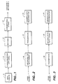
- FIG. 1 shows an environment for a first portion of a system employing the encoding and decoding aspects of the invention.
- an HDTV (high-definition television) camera 10 provides a video source signal.
- the camera output is applied to an optional downconverter 12.
- Either the camera output itself, if in a suitable format, or the downconverter is applied to an encoder 14 according to the present invention.
- the output of the downconverter or the output of the HDTV camera provide a progressively-scanned television signal having substantially the number of active picture scanning lines in a frame as the interlaced SDTV signal provided by the encoder 14 has in a frame ( i.e ., a frame made up of two interlaced fields) and having a progressive scan frame rate substantially the same as the interlaced field rate of the SDTV signal provided by the encoder.
- a frame i.e ., a frame made up of two interlaced fields
- a progressive scan frame rate substantially the same as the interlaced field rate of the SDTV signal provided by the encoder.
- any differences in aspect ratio may be handled by an appropriate scaler which may be part of the optional downconverter.
- the desired output of encoder 14 is an NTSC television signal having 525 lines (nominally 480 active picture lines), 2-1 interlaced, a nominal 60 Hz field rate (as is well known, the actual NTSC color frame rate is 59.94 Hz, however, it will be referred to as 60 Hz in this document and likewise, the 29.97 Hz field rate will be referred to as 30 Hz), and a nominal 30 Hz frame rate
- the input to the encoder should be a non-interlaced progressive scan television signal having a nominal 60 Hz frame rate and 480 active picture lines.
- the optional downconverter 12 is employed. Downconverter 12 should satisfy the Nyquist criteria in all three dimensions (horizontal, vertical and temporal) in order to minimize artifacts in the ultimately reproduced television picture.
- the input signal may be a monochrome video signal or the luminance components of a component color video signal.
- a component video signal may comprise analog or digital components such as RGB (from which luminance and chrominance components may be derived), Y/I/Q, Y/U/V, Y/R-Y/B-Y, Y/Cr/Cb, etc.
- the received digital component video signal may be in any of a number of compressed or uncompressed formats, including, for example, various ones of the digital component video formats in accordance with the recommendations, standards or compression algorithms of the CCIR (International Radio Consultative Committee) (such as the hierarchy of digital video coding formats under CCIR Recommendation 601, the 4:2:2 format often being referred to as a CCIR 601 video signal), ISO/MPEG (the Motion Picture Experts Group of the International Standards Organization), SMPTE (Society of Motion Picture and Television Engineers), EBU (European Broadcasting Union), and/or the recommendations or standards of other industry, governmental or quasi-governmental bodies.
- CCIR International Radio Consultative Committee
- ISO/MPEG the Motion Picture Experts Group of the International Standards Organization
- SMPTE Society of Motion Picture and Television Engineers
- EBU European Broadcasting Union
- the output of the encoder 14 is then employed by a conventional television "studio" 16 which operates in accordance with the interlaced SDTV signal provided by the encoder.
- the studio 16 may include, for example, television production, recording and/or editing facilities.
- the studio 16 may also receive interlaced SDTV signals from video sources and motion picture film sources not processed by an encoder of the present invention.
- the output of the conventional studio 16 in the Figure 1 arrangement may be used to provide an interlaced SDTV signal to be used in a conventional way as, for example, for standard NTSC transmission or recording.
- the output of the conventional studio may advantageously be employed as part of a system employing a decoder according to the present invention.
- Figures 2 and 3 show alternative environments for completing such a system.
- the interlaced SDTV signal output of the conventional studio 16 is upconverted to any desired HDTV format in block 20 and the signal is then applied to a transmission block 22.
- the transmission block may include wired and/or wireless transmission and/or recording.
- the transmission output is then applied to a viewer's HDTV television set 24, operating in accordance with the HDTV format of block 20.
- Upconverter 20 includes a decoder according to the present invention.
- the output of the conventional studio 16 is applied to a transmission block 30.
- the transmission block may include both wired and/or wireless transmission and/or recording.
- the transmission output is then applied to an upconverter 32 which upconverts the compatible standard-bandwidth television signal to any desired HDTV format in block 32.
- the HDTV signal is then applied to a viewer's HDTV television set 34, operating in accordance with the HDTV format of block 32.
- the transmission block carries an HDTV signal whereas in the arrangement of Figure 3 , the transmission block carries an interlaced SDTV signal.
- FIG 4 a functional block diagram, shows an embodiment of the encoder of the present invention being fed by an HDTV camera and an optional downconverter.
- the output of an HDTV camera (not shown) is applied to the optional downconverter 402.
- the downconverter 402 may include a space-domain lowpass filter (typically, a vertical-domain lowpass filter) 404 and a scaler 406.
- the camera output or the downconverter output if a downconverter is required, is applied to the encoder, shown here as the remaining portion 407 of Figure 4 .
- the substantially alias-free progressively-scanned television signal is applied to three paths - two signal processing paths and a control signal generating path.
- the upper signal processing path 408 is a low-motion signal processor providing a first intermediate interlaced television signal having low motion content.
- the lower signal processing path 410 is a high-motion signal processor providing a second intermediate interlaced television signal having high motion content.
- the low-motion signal processor in path 408 includes a time-domain lowpass filter 412.
- this temporal filter averages two successive frames.
- the input is applied to a one-frame delay 502 and to a summing node 504 which also receives the one-frame delayed output of the input signal.
- the output of the summing node 504 is then scaled in amplitude by one-half in scaler 506.
- four successive frames may be averaged.
- filter 412 has a threshold such that it does not operate on signals below a certain amplitude level, for example, a level commensurate with the noise level.
- the purpose of the temporal filter 412 is to provide greater adherence to the Nyquist criterion in the time domain.
- temporal aliasing artifacts are visible for some camera conditions.
- the slow panning of a scene may cause a visible "juddering" effect.
- Another purpose for temporal filter is to provide a good balance between the signal processing timings of the paths 408 and 410.
- the output of the temporal filter 412 remains a progressively-scanned television signal with the same frame rate and number of active picture lines as the input signal. This provides the same sharp image for still or slow moving objects as does the input signal to the time-domain lowpass filter.
- the temporal filter 412 In order for the low-motion process of path 408 to provide a reasonable picture content alignment with the fields produced by the high-motion process of path 410, the temporal filter 412 must process an even number of frames (i.e., 2, 4, etc.). In practice, a two frame averaging is preferred, although averaging over four frames is practical although at greater cost and complexity.
- the temporal lowpass filter 412 may also be adaptive such that it varies the number of frames over which it averages in response to the content of one or more frames.
- the output of the temporal filter 412 is applied to a drop-frame-and-repeat function 414 which eliminates every other progressively-scanned frame and repeats every non-eliminated frame thereby providing pairs of processed identical progressively-scanned television signal frames having the same frame rate as the progressively-scanned television signal received by time-domain lowpass filter 412 but having a motion resolution of one-half its progressive scan frame rate.
- the signal at the output of block 414 is equivalent to that which would result if the source were a film source having a frame rate half of the frame rate of the progressively-scanned signal - every two successive frames are identical (e.g ., a 30 frame/second motion picture film in a 60 Hz NTSC system or a 25 frame/second motion picture film in a 50 Hz PAL system).
- block 414 provides a field merge signal indicating which pairs of frames are identical.
- a marker signal is usable in the decoder to identify which pair of fields of the interlaced signal received at the decoder should be merged to reconstruct the progressively-scanned signal.
- the decoder could be simplified and there would be no need to transmit a marker signal (the decoder would simply employ well-known techniques to identify the even and odd parity fields making up each interlaced frame).
- the decoder is capable, albeit with greater complexity, of determining which pair of fields should be merged without receipt of a marker signal or the adoption of such a convention.
- the output of the drop-frame-and-repeat process 414 is applied to an interlacer 416 providing an interlaced television signal having substantially the number of active picture scanning lines in a frame ( i.e ., two interlaced fields) as the processed progressively-scanned television signal has in a frame and having an interlaced field rate substantially the same as the frame rate of the processed progressively-scanned television signal.
- the interlacer creates the two opposite parity fields of each interlaced frame (or, alternatively, the two successive opposite parity fields from different interlaced frames) from each pair of identical progressively-scanned frames, dropping every other line in the pairs of identical progressively-scanned frames, the dropped lines being offset by one line from frame to frame.
- Such interlacers are known in the prior art in connection with converting motion picture film to video (i.e., the telecine art).
- the motion content or motion resolution of the resulting interlaced signal is at the interlaced frame rate rather than the field rate because each pair of fields is derived from a pair of identical progressively-scanned frames.
- the interlacer 416 output is applied to a delay match 418 which provides any time delay necessary to synchronize the timing of the signal outputs from paths 408 and 410.
- the high-motion signal processor in path 410 includes a space-domain lowpass filter 420.
- the space-domain filter provides vertical-domain filtering by taking a weighted average of five successive horizontal lines, although this is not critical.
- Such filters are well known in the art.
- the purpose of such a filter is to suppress a type of aliasing, the perceived flickering caused of single horizontal lines when they are moving vertically or the horizontal edges of objects when they are moving vertically.
- the space-domain lowpass filter may also include a horizontal lowpass filter in order to further reduce aliasing artifacts caused by horizontal motion.
- filter 420 has a threshold such that it does not operate on signals below a certain amplitude level, for example, a level commensurate with the noise level.
- the space-domain lowpass filter 420 is applied to an interlacer 422 providing an interlaced television signal having substantially the number of active picture scanning lines in a frame (i. e. , two interlaced fields) as the space-domain lowpass filtered progressively-scanned television signal has in a frame and having an interlace field rate substantially the same as the frame rate of the space-domain lowpass filtered progressively-scanned television signal.
- interlacer 422 creates the two opposite parity fields of each interlaced frame from consecutive pairs of space-domain lowpass filtered progressively-scanned frames, wherein the interlacer drops every other line in the progressively-scanned frames to create each field, the dropped lines being offset by one line from frame to frame.
- interlacer 416 Unlike in interlacer 416 in the low-motion path, the consecutive pairs of progressively-scanned frames, from which the pairs of interlaced fields are derived by interlacer 422, are not always identical.
- the motion content or motion resolution of the resulting interlaced signal is at the interlaced field rate because each field in a pair is derived from a different progressively-scanned frame.
- Interlacers such as interlacer 422 are known in the art.
- the interlacer 422 output is applied to a delay match 424 which provides any time delay necessary to synchronize the timing of the signal outputs from paths 408 and 410.
- the outputs of the respective processor paths 408 and 410 are applied to inputs of a type of switch 426, often referred to as a fader or soft switch, shown schematically as a potentiometer, the output of which, the interlaced SDTV signal output, is taken from the adjustable tap.
- a type of switch 426 often referred to as a fader or soft switch, shown schematically as a potentiometer, the output of which, the interlaced SDTV signal output, is taken from the adjustable tap.
- the position of the tap, and therefore the degree to which the output of one path or another or some mixture of the two is taken as the encoder output, is controlled by a motion control signal produced by a motion control generator 428.
- the motion control signal is derived from differences in picture information from frame to frame of the progressively-scanned television signal input (the progressive scan frame rate being the same as the interlace scan field rate), the differences indicating the degree of motion in the progressively-scanned television signal (and consequently, in the resulting interlaced SDTV signal produced by the encoder). As the tap position is varied, the motion resolution of the resulting output signal varies.
- the switch 426 may be implemented in any of various ways (electronically or by software, for example) which allow its rapid control such that changes in path selection within a field of the output interlaced signal are readily accomplished in real time.
- motion control generator 428 detects differences between progressively-scanned frames on a pixel-by-pixel basis and generates a motion control signal responsive to differences in blocks of pixels from frame to frame in the input progressively-scanned signal.
- the motion control generator is responsive to the velocity, size and amplitude of the picture movement.
- the motion control generator is able to detect panning, where the entire picture (the entire frame) may be said to be moving.
- the motion control signal may cause the switch to transition between the low-motion and high-motion mode outputs of paths 408 and 410 many times within each field, the extent to which one path or the other is selected depending on the degree of motion (based on a weighting of size, velocity and amplitude) throughout the picture.
- the motion control signal should select the low motion path output when motion in the displayed picture would appear to the eye as smooth and continuous when displayed with the motion resolution produced by the low motion path; otherwise, it should select the high motion path output.
- the switch will select the low-motion mode for at least a portion of each field (the entire field for the case of a still scene).
- the switch In the very rare case of the HDTV camera source rapidly panning a still scene (for example, panning across the side of a mountain at a high motion rate (i.e ., a rate greater than 30 Hz for NTSC), the switch would select the high-motion mode during the entire field.
- a pan of a running player in a football game the camera tracking the runner
- the motion control signal default condition is such as to cause the switch 426 to select only the low-motion output of path 408.
- the motion control generator 428 may also generate an optional pseudo-film YES/NO signal, the signal being in its YES condition for all conditions except when the entire field is in the high-motion mode.
- the output signal from switch 426 is an interlaced signal having a baseline motion resolution at its frame rate, but in which high-motion "holes" occur within fields. Rarely, as just discussed above, entire fields have field rate motion, causing a break in the pseudo-film pattern.
- the result for most signal conditions is pairs of interlaced fields which are derived at least in part from the same progressively-scanned frame: they are from the same progressively-scanned frame for those portions in which the field is produced by the low-motion process.
- Such an interlaced field pattern generated by the encoder of the present invention is defined herein as a "pseudo-film pattern.”
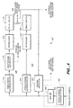
- Figure 6 shows a functional block diagram of a decoder according to a preferred embodiment of the invention.
- the decoder forms a portion of the "Upconvert to HDTV Format" block 20 of the Figure 2 arrangement or the "Upconvert to HDTV Format” block 32 of the Figure 3 arrangement.
- the input of the Figure 6 decoder is the input to block 20 ( Figure 2 ) or block 32 ( Figure 3 ), namely a interlaced SDTV signal.
- the output of the Figure 6 decoder, a reconstructed progressive scan television signal has substantially the number of active picture scanning lines in a frame as the interlaced SDTV signal has in a frame (i.e., two interlaced fields) and has a progressive scan frame rate substantially the same as the interlace field rate of the interlaced television signal.
- the encoder output is further upconverted, for example, by increasing the number of progressive scan lines or frames and/or changing the aspect ratio. Such further upconversion may be accomplished by any of various known techniques.
- Path 602 includes a 24 Hz film source video processor 612.
- Elements related to processor 612 include, in control signal path 610, a field- or frame-based motion detector 614 and a 24 Hz film pattern detector 616.
- Motion detector 614 detects motion between fields or frames of the input interlaced SDTV signal and sends a signal responsive to such motion to a 24 Hz film pattern detector 616.
- a field-based motion detector is preferred.
- Frame-based motion detectors are well known in the art.
- the 24 Hz film pattern detector 616 generates a field merge signal which is applied to the 24 Hz film source video processor 612 and a pattern YES/NO signal which controls switch 618. When a 24 Hz film pattern is detected, the film YES condition causes switch 618 to select the output the 24 Hz film source video processor as the decoder output.
- Film pattern detector 616 looks for the pattern caused by a 24 Hz (24 frame/sec) motion picture film source in a 60 Hz NTSC signal.
- the detection of 3-2 pulldown 24 Hz film patterns in 60 Hz video signals is well known in the art. See, for example, said United States Patents 4,876,596 ; 4,982,280 ; and 5,291,280 .
- a 50 Hz PAL format input signal which may carry 25 Hz (25 frame/sec) motion picture sources
- the 24 Hz film pattern detector 616, the 24 Hz film source video processor 612 and the switch 618 are not required.
- the detection of 25 Hz film sources in 50 Hz PAL signals may be detected by the same decoder elements, described below, which detect a pseudo-film pattern in a 50 Hz PAL signal.
- the film source video processing provided by processor 612 may be any known processing techniques for deriving progressively-scanned video signals from an interlaced film-source video signal, including, for example, any of the techniques disclosed in said three United States patents, cited just above.
- the output of a combiner 620 which receives the outputs of paths 604 and 606 as its inputs, is selected as the decoder output.
- a field-based motion detector 622 detects motion between fields and produces two motion signals, one responsive to high motion and another responsive to low motion. Details of such a motion detector are set forth below in connection with Figure 8 .
- the field motion signal from the field-based motion detector 622 is applied to a pseudo-film pattern detector 624.
- a field-based motion detector is required to detect a pseudo-film pattern.
- the pseudo-film detector looks for a pattern similar to that which would be caused by a 30 Hz (30 frame/sec) motion picture film source.
- the pseudo-film detector looks for a pattern similar to that which would be caused by a 30 Hz (30 frame/sec) motion picture film source.
- the pseudo-film detector looks for a pattern similar to that which would be caused by a 30 Hz (30 frame/sec) motion picture film source.
- the pseudo-film detector looks for a pattern similar to that which would be caused by a 30 Hz (30 frame/sec) motion picture film source.
- the pseudo-film detector looks for a pattern similar to that which would be caused by a 30 Hz (30 frame/sec) motion picture film source.
- the video sequences in adjacent video fields are compared a 010101, etc. pattern results, indicating a pseudo-film source.
- the pseudo-film pattern differs from a true film pattern in that there are portions of the pairs of fields derived from the same progressively-scanned frame which are not derived from the same progressively-scanned frame due to transient occurrences of high motion.
- a modified 30 Hz film detector may be employed for the case of an NTSC signal input (or a modified 25 Hz film detector may be employed for the case of a PAL signal input).
- a 30 Hz film detector is disclosed in said 4,982,280 patent.
- a detector designed for film source detection may require some modification such that, in the case of NTSC, for example, it ignores areas of high motion within an otherwise low motion pattern.
- the detector should generate a pseudo-pattern YES condition signal in response to all fields in which any portion of the field includes only low motion.
- a threshold intended to eliminate false indications due to noise
- the detector should generate a pseudo-pattern YES condition signal in response to all fields in which any portion of the field includes only low motion.
- almost all fields are part of a pseudo-film pattern and the pattern is broken only when a field having all high motion is detected, resulting, for example, from the camera source's fast panning of a fully still scene, which is very rare.
- Such motion detector and pattern detector action required to provide the necessary action in the decoder are not disclosed in said United States patent 4,620,225 .
- the pseudo-film pattern detector 624 and the high-motion motion signal from motion detector 622 control a switch or combiner 620 which selects either the output of a pseudo-film source video processor 626 or the output of a conventional video processor 628 or some combination of the two.
- the pseudo-film processor 626 provides for decoding of a pseudo-film signal created by the encoder of the present invention, thereby creating an excellent reconstruction of the input to the encoder.
- the conventional video processing function 628 allows a video signal created by a source other than the encoder of the present invention to be processed.
- the conventional video interlace-to-progressive scan converter 628 may be any of various known interlace-to-progressive scan converters or de-interlacers (sometimes known as line doublers), preferably of the adaptive type which operates on an interfield basis (merging, for example, pairs of fields or a field with an average of the field occurring before and after it) for conditions of low motion and on an intrafield basis (creating new scanning lines by interpolation from lines within the same field).
- the pseudo-film processor 626 is preferably an interlace-to-progressive field-merge-type de-interlacer, a type of line doubler (lines from pairs of interlaced fields are merged to produce the progressively scanned lines).
- line doublers are well known in the art. See, for example said United States patents 5,159,451 and 4,876,596 and said Published International Patent Application WO 94/30006 .
- the function of the decoder is explained by reference to several paths, practical embodiments providing substantially the same functions and results may be implemented in other ways.
- the 24 Hz film pattern detector 616 and the pseudo-film pattern detector 624 may be at least partially combined.
- portions of the pseudo-film source video processor 626 and the conventional video processor 628 may be at least partially combined.
- portions of the field-based motion detector 622 and the field and/or frame-based motion detector may be combined.
- the decoder output may also be applied to an optional upconverter 630 if it is desired to alter the encoder output to accommodate the HDTV format or other format of the viewer's television set.
- Upconverter 630 may, for example, increase the number of progressive scan lines, increase the progressive frame rate, perform a progressive-to-interlace conversion to an interlaced HDTV format or alter the aspect ratio.
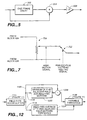
- FIG. 7 Details of the combiner 620 are shown schematically in Figure 7 as comprising a first switch 702 and a second switch in the nature of a fader or soft switch, depicted as a potentiometer 704.
- Switch 702 is controlled by the pseudo-film pattern YES/NO signal such that a YES condition places the switch in its upper position in which it selects the tap of the potentiometer.
- a NO condition places the switch in its lower position in which it selects the output of the conventional video processor 628 ( Figure 6 ).
- the high-motion motion signal from motion detector 622 ( Figure 6 ) controls the position of the potentiometer tap and therefore the degree to which the output of one path or another or some mixture of the two is taken as the decoder output.
- the potentiometer 704 functions as a fader or soft switch.
- the switch may be implemented in any of various ways (electronically or by software, for example) which allow its rapid control such that changes in path selection within a field are accomplished in real time. It should also be understood that in practice, the functions of switches 702 and 704 may be combined.
- the input signal designated "Y in " is applied to an array of field and line memories 802.
- the array of memories 802 provides three outputs comprising time-delayed versions of Y in , which, along with Y in itself, provide four time-spaced versions of the input luminance signal: one in a first television field F0, two in a second television field F1 and one in a third television field F2.
- Figure 8A is a quasi-three-dimensional representation in which the vertical and horizontal dimensions lie in the plane of a television picture field such that the vertical axis is the vertical direction of a television picture field, perpendicular to the scan lines, the horizontal axis is the horizontal direction of the television picture field, parallel to the scan lines, and the direction perpendicular to the plane of each field is a quasi-time axis in which each consecutive field is shown at a discrete time.
- a pixel may be represented as point P(F0) in field F0.
- That pixel is shown in Figure 8A as a point in a horizontal scan line.
- a first pixel in field F1, occurring 262 lines (in the case of NTSC, for PAL, 312 lines) after pixel P(F0), and a second pixel in field F1, occurring 263 lines (in the case of NTSC, for PAL 313 lines) after pixel P(F0), may referred to as pixel P(F1-1 ⁇ 2H) and pixel P(F1+1 ⁇ 2H), respectively.
- Pixel P(F1-1 ⁇ 2H) shown as a point in a first horizontal scan line, is directly above pixel P(F1+1 ⁇ 2H) vertically, which pixel is shown as a point in the next lower horizontal scan line.
- a point P(F1) in field F1 corresponding spatially to the location in which pixel P(F0) of field F0 lies, is half way between pixel P(F1-1 ⁇ 2H) and pixel P(F1+1 ⁇ 2H) due to the interlacing offset of horizontal scan lines from field to field.
- pixel P(F1-1 ⁇ 2H) precedes, by the time of one-half line, the point P(F1), while pixel P(F1+1 ⁇ 2H) is, by the time of one-half line, after the point P(F1).
- the spatial point in field F2 corresponding to that of pixels P(F0) and P(F1) is the location of pixel P(F2), occurring 525 lines, exactly one frame or two fields, after pixel P(F0).
- Pixel P(F2) is shown as a point in a horizontal scanning line in field F2.
- the undelayed input luminance signal stream Y in itself provides the F0 output stream.
- the input luminance signal stream Y in is applied to a first nH delay 804 (where n is 262 lines for NTSC, 312 lines for PAL) to provide the F1-1 ⁇ 2H output stream.
- the output of delay 804 is applied to a 1H (one horizontal line) delay 806 to provide the F1+1 ⁇ 2H output stream.
- the delay 806 output is applied to a further nH delay (where n is 262 lines for NTSC, 312 lines for PAL) 808 to provide the F2 output stream.
- the delays may be implemented by various hardware, software and hybrid hardware/software techniques well known to those of ordinary skill in the art. Although shown as a series of delays, the delays may be implemented in other ways such as by a multiport random access memory in which the signal stream is read in once and read out multiple times, or by other equivalent ways.
- the array of memories 802 provides four signal output streams corresponding to four pixel locations in three consecutive fields: a pixel at time position F0 in field 0, pixels at time positions F1-1 ⁇ 2H and F1+1 ⁇ 2H in field F1, and a pixel at time position F2 in field 2.
- a field 0 motion detector 814 receives the F0, F1-1 ⁇ 2H and F1+1 ⁇ 2H signal streams, signals spaced apart in time by one field minus one-half line and by one field plus one-half line. It is known to apply such inputs to field motion detectors - see, for example, U.S. Patents 4,982,280 and 5,291,280 .
- the purpose of the field motion detector is to detect motion (having a velocity greater than, for example, one half line per field) from interlaced field to interlaced field without falsely detecting motion when a vertical transition occurs (for example, when the portion of the picture below a horizontal line is black and the portion of the picture above the line is white, or vice-versa).
- a field motion detector of the type disclosed in said 5,291,280 patent may be employed in aspects of the present invention, it is preferred to employ the improved field motion detector described below because of its greater resistance to false detection caused by certain types of vertical transitions. While a field motion detector such as that of the 4,982,280 patent may be employed, the field motion detector of said 5,291,280 patent is preferable to that of the 4,982,280 patent in that the earlier patent provides no immunity at all to false detection resulting from vertical transitions.
- the output of the field 0 motion detector 814, F0 mtn which, in a digital embodiment is a multibit word indicating motion amplitude, provides a field to field motion signal which is applied to the pseudo-film pattern detector 624 ( Figure 6 ).
- the F0 mtn signal is also used as one of two signals for deriving a high-motion motion signal, as described below.
- a second field motion detector, field 2 motion detector 816 receives the F2, F1-1 ⁇ 2H and F1+1 ⁇ 2H signal streams, signals also spaced apart in time by one field minus one-half line and by one field plus one-half line.
- the output of the first field motion detector may be delayed by one field (in practice, by one field plus or minus a half line).
- the output of the field 2 motion detector 816, F2 mtn which, in a digital embodiment is a multibit word indicating motion amplitude, also provides a field to field motion signal which is, with the F0 mtn signal, usable to derive a high-motion motion signal, as described below.
- the F2 mtn signal may be used, in the manner described below, to verify the pseudo-film pattern detected using the F0 mtn signal.
- Motion detectors 814 and 816 compare corresponding pixels in three successive fields, P(F0), P(F1) and P(F2) (it being understood that due to the interlace offset, in the middle field pixels just above and just below the picture location corresponding to pixels P(F0) and P(F2) are employed). There are four possibilities with respect to the three pixels:
- Case one indicates no motion. Cases two and three indicate low motion and case four indicates high motion. Thus, a Boolean exclusive-OR function indicates low motion and a Boolean AND function indicates high motion as illustrated in the following table: Field 0 - Field 1 Field 1 - Field 2 Low Motion (Exclusive-OR) High Motion (AND) 0 0 0 0 0 1 0 1 0 0 1 1 0 1 0 1 0 1
- the Boolean AND function operating on the resulting binary signals generates an indication of high motion conditions. That indication may be used to select either the F0 mtn signal or the F2 mtn signal which has the greater amplitude or some combination of the two signals (such as their average amplitude) to produce the high motion signal for control of combiner 620 ( Figure 6 ).
- the F0 mtn signal, the F2 mtn signal and the resulting high motion signal indicate the motion amplitude and, in a digital implementation, are multibit words.
- a logic function 818 provides such appropriate Boolean AND and selection or combining functions.
- the high motion control signal causes the combiner 620 ( Figure 6 ) to select only the pseudo-film source video processor 626 output.
- the Boolean AND function is one, indicating the third case, the high motion control signal causes the fader or soft switch function of the combiner 620 to swing between the pseudo-film and conventional processors in accordance with the amplitude of the motion (greater motion moving the fader toward the conventional video processor output).
- logic 818 includes an Exclusive-OR function responding to binary-converted forms of the F0 mtn and F2 mtn signals
- a further signal may be provided to verify the pseudo-film mode condition.
- this further signal may be used to in conjunction with a modified pseudo-film pattern detector.
- the detector could be modified, for example, to identify a field as a pseudo-film field so long as the field did not contain any occurrences of the fourth condition ( i.e ., P(F0) ⁇ P(F1) ⁇ P(F2)).
- the field-based motion detector 622 may be used in place of the field or frame-based motion detector 614 ( Figure 6 ), in which case the F0 mtn signal ( Figure 8 ) is applied to the 24 Hz film pattern detector 616 ( Figure 6 ) and to the conventional video processor 628 ( Figure 6 ).
- the decoder may receive a pseudo-film YES/NO signal, a field merge signal, and/or a high-motion signal from the encoder.
- a pseudo-film YES/NO signal e.g., a pseudo-film YES/NO signal
- a field merge signal e.g., a field merge signal
- a high-motion signal e.g., a high-motion signal
- Each field motion detector compares temporally adjacent pixel information of opposing field parity (field 0 and field 1, for example) and differentiates field-to-field motion from vertical picture transitions to provide a field motion signal.
- Each field motion detector includes three subtractors (902, 904 and 906), a keep-smaller-absolute-value function 908, a magnitude comparator 910, and a motion/no-motion switch 912.
- Subtractor 902 receives the F1-1 ⁇ 2H and F0 signals.
- Subtractor 904 receives the F0 and F1+1 ⁇ 2H signals.
- Subtractor 906 receives the F1-1 ⁇ 2H and F1+1 ⁇ 2H signals.
- the field motion detector described in U.S. Patent 5,291,280 employs subtractors 902 and 904, receiving the same inputs as just described, and the keep-smaller-absolute-value function 908.
- the field motion detectors of the present invention may use the same keep-smaller-absolute-value function arrangement as in said 5,291,280 patent.
- Inter-field subtractions yield field motion but also incorrectly detect vertical transitions as motion.
- the keep-smaller-absolute-value function chooses the smaller of the two inter-field subtractions and thereby differentiates high frequency vertical transitions from motion.
- this preferred field motion detector adds a single line vertical differentiator (the third subtractor 906), whose output, a measure of vertical energy, is compared in magnitude comparator 910 to the output of the keep-smaller-absolute-value function 908, an measure of field motion.
- Subtractor 906 functioning as a single line vertical differentiator, looks for a vertical transition within a field.
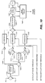
- FIG. 10 A preferred form of a frame motion detector for use as motion detector 614 ( Figure 6 ) (if a frame motion detector is used instead of a field motion detector) is shown in detail in Figure 10 , in which F0 and F2 video stream signals are compared on a pixel by pixel basis to determine if the corresponding pixel in field F1 is likely to be in motion. A one frame memory delay (not shown) is used to provide the F2 video stream signal.
- the subtractor 1002 output is then put through complementary lowpass and highpass filters created by a lowpass filter 1004 and subtractor 1006.
- the lowpass filter may be a five-tap FIR filter with a zero at the color subcarrier frequency (in a frame detector intended for use with both NTSC and PAL, the filter characteristics may be switchable in accordance with whether an NTSC or PAL signal is being processed).
- the horizontal lowpass filtered path (where most of the motion lies) on line 1008 is rectified in rectifier 1010, and applied to a threshold function 1012 which removes noise components by applying a motion LPF noise threshold.
- the threshold 1012 may, for example, limit the signal to four bits (from, say, eight bits).
- the horizontal highpass filtered path on line 1014 goes into complementary vertical lowpass and highpass filters created by subtractor 1016, adder 1018 and delay 1020 (which provides a one-line delay for NTSC and a two-line delay in PAL).
- These paths, vertical HPF path 1022 and vertical LPF path 1024, are then individually rectified in rectifiers 1026 and 1028, respectively, and have their own thresholds (threshold functions 1030 and 1032, respectively, which remove noise components by applying a motion HHPF-VHPF Noise threshold and a motion HHPF-VLPF Noise threshold, respectively) (where HHPF is horizontal highpass filter, etc.).
- the thresholds 1030 and 1032 may also limit the respective signals to 4 bits.
- three paths are provided: a horizontally lowpass filtered (HLPF) path, a horizontally highpass filtered and vertically highpass filtered (HHPF-VHPF) path, and a horizontally highpass filtered and vertically lowpass filtered (HHPF-VHPF) path.
- the purpose of three paths is to separate color subcarrier signal components from true motion information.
- the HLPF path output has substantially no subcarrier signal components as a result of the horizontal lowpass filtering action of LPF 1104.
- the two HHPF paths, carrying the complement of the HLPF path require vertical filtering to reduce the subcarrier signal components present in the high-frequency portion of the spectrum. Such components have the appearance of a vertical line pattern which may occur in real television scenes.
- the filtering action of the HHPF-VHPF path passes low amplitude level subcarrier signal components.
- the filtering action of the HHPF-VLPF path rejects subcarrier components (which have a vertical component because they are out-of-phase from line to line) but passes horizontally moving patterns of lines (referred to as "moving multiburst") which must be detected as motion (such a pattern is rejected by the other two paths).
- the HHPF-VLPF path may have a lower threshold level than does the HHPF-VHPF path because the HHPF-VLPF path is not differentiating desired from undesired signal components based on amplitude.
- the HLPF and HHPF-VLPF threshold levels are selected for noise immunity.
- the three differently filtered motion paths are then combined in summer 1034 and expanded in expansion function 1036.
- they are expanded horizontally by 5 pixels, temporally by 1 field and vertically by 1 line.
- Techniques for such horizontal, vertical and temporal expansion are known. See for example, said U.S. Patent 5,488,422 .
- the output of block 1036 is applied to one input of a keep greater value function 1038 and to a 262H/312H (262 lines for NTSC, 312 lines for PAL) delay 1040, the output of which is applied as a second input to block 1038, and to a 1H (one line) delay 1042, the output of which is applied as a third input to block 1038.
- Blocks 1036-1042 provide a temporally and vertically expanded motion signal.
- temporal and vertical expansion are twofold - to avoid the situation when a fast moving object leaves a "hole” between frames (e.g., a swinging pendulum) and, in the case of an NTSC signal, to avoid an appearance of fluttering between sharp and soft pictures when film material is not detected as film material. Also, expansion assures that the frame motion signal "surrounds" the field motion signal in the pseudo-film detector.
- the frame motion detector has three adjustable parameters: the motion LPF noise threshold, the motion HHPF-VLPF noise threshold, and the motion HHPF-VHPF noise threshold.
- the parameters should be adjusted to as to minimize false detection of motion caused by noise and subcarrier signal components.
- the purpose of the pseudo-film pattern detector 624 ( Figure 6 ) is to determine the onset of a pseudo-film pattern, thus entering the pseudo-film mode (indicated by putting the pseudo-film YES/NO signal in its YES condition), and, after entering the pseudo-film mode, when the pseudo-film pattern is broken, exiting the pseudo-film mode (indicated by putting the pseudo-film YES/NO signal in its NO condition).
- the pseudo-film pattern detector 624 receives the field motion signal from field-based motion detector 622.
- the pseudo-film pattern detector is basically the same as a PAL film detector, which looks for 25 Hz sources in a 50 Hz television signal or an NTSC 30 Hz film detector, which looks for 30 Hz sources in a 60 Hz television signal.
- a field-based film detector for detecting 25 frame/second motion in PAL television signals is disclosed in said Published International Patent Application WO 94/30006
- a field-based film detector for detecting 30 frame/second motion in NTSC television signals is disclosed in said U.S. Patent 4,982,280 .
- the pseudo-film detector examines the accumulated field motion between field 0 and field 1 and then searches for the 30 Hz (30 Hz for NTSC, 25 Hz for PAL) field motion pseudo-film sequence pattern "1 0" before determining if the material is pseudo-film and not other video.
- the pseudo-film detector receives the F0 mtn output signal of the field 0 motion detector 813 ( Figure 8 ).
- the field motion signal is filtered in low-pass filter 1102 to remove subcarrier residue, rectified in rectifier 1104, and blanked by pseudo-film motion blanking function 1106 to keep any picture edge artifacts and subtitles from being detected as motion.
- the rectified and blanked motion signal is then applied to a threshold 1108 to reduce noise artifacts.
- the threshold is set by a fixed and predefined pseudo-film noise threshold.
- the motion input from a frame motion detector (if used) is thresholded by a threshold 1110 into, in a digital implementation, a one-bit motion yes/no signal.
- This threshold is set by a motion threshold.
- the one-bit motion yes/no signal is then used to control a motion-no motion switch 1112.
- the optional frame motion indication serves as a verification of the field motion indication - if there is no frame motion at a given pixel then there cannot be any field motion for the same pixel (the frame motion has been expanded horizontally and vertically to assure that the band of frame motion surrounds the field motion).
- the one-bit field motion signal from switch 1112 is then accumulated over the entire field in a field rate accumulator 1114.
- the recurring pseudo-film sequence "1 0" can occur on standard video material for a few frames in a row so care must be taken to differentiate pseudo-film source video from conventional video.
- the arrangement in the pseudo-film detector between the field rate accumulator 1114 and the state machine 1130 may be modified by substituting the arrangement of Figure 12 , described below.
- the motion sign is fed into the pseudo-film state machine 1150, which may be the same type of state machine as in said 4,982,280 patent. If not, a 0 is input. Pseudo-film mode is entered once the number of film sequences reaches the pseudo-film sequence acquisition number. Exiting the pseudo-film mode occurs when the pseudo-film sequence is disrupted by a field in which the entire field is high motion.
- the pseudo-film detector has eight adjustable parameters: a pseudo-film noise threshold, a motion threshold, a pseudo-film sequence acquisition number, a minimum motion ratio and four pseudo-film blanking parameters that define the area of pseudo-film motion detection: pseudo-film blanking top line, pseudo-film blanking bottom line, pseudo-film blanking right side, and pseudo-film blanking left side.
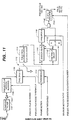
- Figure 12 shows an alternative arrangement for a portion of the pseudo-film detector of Figure 11 .
- the data is latched in and the motion value is then passed from field rate accumulator 1114 ( Figure 11 ) into three parallel paths, 1216, 1218 and 1220: 1) path 1216 to a minimum of five field detector 1222 (although a minimum of five fields is preferred to provide a safety margin, a minimum of three fields is practicable), 2) path 1218 to a three field weighted averager 1224, and 3) path 1220 to one side of a subtractor 1226 where end-of-field calculations are performed.
- the accumulators are reset.
- the minimum-of-five field detector 1222 looks at five adjacent fields for the minimum motion. For pseudo-film in five adjacent fields there will always be a non-moving field, and therefore the minimum motion value will correspond to it.
- This output provides the other input to the subtractor 1226 in order to remove the base motion value associated with a non-moving field from the accumulator 1214 output on path 1220.
- the subtractor 1226 output is then passed to a variable threshold 1228 whose threshold is determined by the output of block 1224, the weighted average of three fields.
- the minimum motion detector 1222 and the weighted averager 1224 greatly increase the sensitivity of pseudo-film detection on small moving scenes and factor out computer generated material which violates the Nyquist criterion.
- the output of the variable threshold 1228, a "1" for a moving field and a "0" for a non-moving field, is then fed into the state machine 1130 ( Figure 11 ).
Landscapes
- Engineering & Computer Science (AREA)
- Multimedia (AREA)
- Signal Processing (AREA)
- Computer Graphics (AREA)
- Television Systems (AREA)
Claims (22)
- Vorrichtung zum Ableiten eines SDTV-Zeilensprungverfahrensignals aus einem Vollbildverfahren-Fernsehsignal, welches im Wesentlichen die Anzahl von aktiven Bildabtastzeilen in einem Rahmen wie das SDTV-Zeilensprungverfahrensignal in einem Rahmen, der aus zwei Zeilensprungverfahren-Halbbildern aufgebaut ist, aufweist und welches eine im Wesentlichen gleiche Vollbildverfahren-Vollbildrate wie die Zeilensprungverfahren-Halbbildrate des Fernsehsignals mit der kompatiblen Standardbandbreite aufweist, wobei das Vollbildverfahren-Fernsehsignal, welches aus einer HDTV-Quelle erzeugt oder abgeleitet wird, umfasst:einen Prozessor für Signale mit geringer Bewegung, welcher das Vollbildverfahren-Fernsehsignal empfängt und ein SDTV-Zeilensprungverfahrensignal bereitstellt, welches eine im Wesentlichen gleiche Halbbildrate wie die Vollbildverfahren-Vollbildrate aufweist, aber in welchem Änderungen in der aktiven Bildinformation des Fernsehsignals nicht die Zeilensprungverfahren-Fernsehsignalhalbbildrate überschreiten, wobei der Verarbeitungspfad für Signale mit geringer Bewegung ein Zeitbereichtiefpassfilter aufweist,einen Prozessor für Signale mit großer Bewegung, welcher das Vollbildverfahren-Fernsehsignal empfängt und ein SDTV-Zeilensprungverfahrensignal bereitstellt, welches eine im Wesentlichen gleiche Halbbildrate wie die Vollbildverfahren-Vollbildrate aufweist, in welchem Änderungen in der aktiven Bildinformation des Zeilensprungverfahren-Fernsehsignals die Zeilensprungverfahren-Fernsehsignalvollbildrate überschreiten kann, aber die Zeilensprungverfahren-Fernsehsignalhalbbildrate nicht überschreitet,einen Bewegungssteuerungsgenerator, welcher das Vollbildverfahren-Fernsehsignal empfängt und ein Bewegungssteuerungssignal bereitstellt, welches aus Unterschieden der Bildinformation von Vollbild zu Vollbild des Vollbildverfahren-Fernsehsignals abgeleitet wird und den Grad einer Bewegung in dem Vollbildverfahren-Fernsehsignal anzeigt, undeinen Schalter, welcher von dem Bewegungssteuerungssignal gesteuert wird, und welcher die Signalausgabe des Prozessors für Signale mit geringer Bewegung und die Signalausgabe des Prozessors für Signale mit großer Bewegung empfängt, um entweder die Signalausgaben oder eine Mischung der Signalausgaben gemäß dem Grad der von dem Bewegungssignal angezeigten Bewegung auszuwählen, um das SDTV-Zeilensprungverfahrensignal zu erzeugen, wobei das Signal eine veränderliche Bewegungsauflösung aufweist.
- Vorrichtung nach Anspruch 1, wobei der Prozessor für Signale mit geringer Bewegung umfasst:das Zeitbereichtiefpassfilter, wobei das Filter das Vollbildverfahren-Fernsehsignal empfängt und ein zeitbereichtiefpassgefiltertes Vollbildverfahren-Fernsehsignal bereitstellt,einen Prozessor zum Verwerfen eines Vollbildes und zum Wiederholen eines Vollbildes, welcher das zeitbereichtiefpassgefilterte Vollbildverfahren-Fernsehsignal empfängt, jedes zweite Vollbildverfahren-Vollbild entfernt und jedes nicht entfernte Vollbild wiederholt und Paare von identischen Vollbildverfahren-Fernsehsignalvollbildern bereitstellt, welche die gleiche Vollbildrate wie das Vollbildverfahren-Fernsehsignal, welches von dem Zeitbereichtiefpassfilter empfangen wird, aufweisen, wobei das verarbeitete Vollbildverfahren-Fernsehsignal eine Bewegungsauflösung von der Hälfte seiner Vollbildverfahren-Vollbildrate aufweist, undeine Zeilensprungvorrichtung, welche das verarbeitete Vollbildverfahren-Fernsehsignal empfängt und ein Zeilensprungverfahren-Fernsehsignal bereitstellt, welches im Wesentlichen die Anzahl von aktiven Bildabtastzeilen in einem Vollbild, welches aus zwei Zeilensprungverfahren-Halbbildern aufgebaut ist, wie das verarbeitete Vollbildverfahren-Fernsehsignal in einem Vollbild aufweist, und welches eine im Wesentlichen gleiche Zeilensprungverfahren-Halbbildrate wie die Vollbildrate des verarbeiteten Vollbildverfahren-Fernsehsignals aufweist, wobei die Zeilensprungvorrichtung zwei Halbbilder mit entgegengesetzter Parität eines jeden Zeilensprungverfahren-Vollbildes aus jedem Paar von identischen Vollbildverfahren-Vollbildern erzeugt bzw. wobei die Zeilensprungvorrichtung jede zweite Zeile in dem Paar von identischen Vollbildverfahren-Vollbildern entfernt, wobei die entfernten Zeilen um eine Zeile von Vollbild zu Vollbild versetzt sind.
- Vorrichtung nach Anspruch 1 oder Anspruch 2, wobei der Prozessor für Signale mit großer Bewegung umfasst:ein Raumbereichtiefpassfilter, welches das Vollbildfernsehsignal empfängt und ein raumbereichtiefpassgefiltertes Vollbildfernsehsignal bereitstellt, wobei das Raumbereichtiefpassfilter zumindest in dem vertikalen Bereich wirkt, undeine Zeilensprungvorrichtung, welche das raumbereichtiefpassgefilterte Vollbildfernsehsignal empfängt und ein Zeilensprungverfahren-Fernsehsignal bereitstellt, welches im Wesentlichen die Anzahl von aktiven Bildabtastzeilen in einem Vollbild, welches aus zwei Zeilensprungverfahren-Halbbildern aufgebaut ist, wie das raumbereichtiefpassgefilterte Vollbildfernsehsignal in einem Vollbild aufweist, und welches eine im Wesentlichen gleiche Zeilensprungverfahren-Halbbildrate wie die Vollbildrate des raumbereichtiefpassgefilterten Vollbildverfahren-Fernsehsignals aufweist, wobei die Zeilensprungvorrichtung zwei Halbbilder mit entgegengesetzter Parität eines jeden Zeilensprungverfahren-Vollbildes aus aufeinander folgenden Paaren von raumbereichtiefpassgefilterten Vollbildverfahren-Vollbildern erzeugt, wobei die Zeilensprungvorrichtung jede zweite Zeile in den Vollbildverfahren-Vollbildern entfernt, um jedes Halbbild zu erzeugen, wobei die entfernten Zeilen von Vollbild zu Vollbild um eine Zeile versetzt sind.
- Vorrichtung nach Anspruch 3, wobei das Raumbereichtiefpassfilter ein Filtern in dem vertikalen Bereich und dem horizontalen Bereich bereitstellt.
- Vorrichtung nach Anspruch 1, wobei die Vorrichtung ferner das Bewegungssteuerungssignal als eine Ausgabe zusätzlich zu dem SDTV-Zeilensprungverfahrensignal bereitstellt.
- Vorrichtung nach Anspruch 1, wobei der Verarbeitungspfad für Signale mit geringer Bewegung einen Prozessor zum Entfernen und Wiederholen eines Vollbildes, welcher jedes zweite Vollbildverfahren-Vollbild entfernt und jedes nicht entfernte Vollbild wiederholt, und eine Zeilensprungvorrichtung aufweist, welche die Halbbilder eines jeden Zeilensprungverfahren-Vollbildes aus den entsprechenden wiederholten Vollbildverfahren-Vollbildern ableitet, wobei die Vorrichtung ein Signal erzeugt, welches anzeigt, welches Paar von Zeilensprungverfahren-Halbbildern richtig zusammengepaart ist, und wobei die Vorrichtung ferner das Signal als eine Ausgabe zusätzlich zu dem SDTV-Zeilensprungverfahrensignal bereitstellt.
- Vorrichtung nach Anspruch 1, wobei der Bewegungssteuerungsgenerator ein Bewegungssteuerungssignal in Abhängigkeit einer Bewegung in Abschnitten eines Fernsehvollbildes derart erzeugt, dass das Bewegungssteuerungssignal den Schalter steuert, seine Auswahl von Prozessoren während eines Halbbildes des erzeugten Zeilensprungverfahren-Fernsehsignals zu ändern.
- Vorrichtung nach Anspruch 7, wobei der Bewegungssteuerungsgenerator Unterschiede zwischen Vollbildern auf einer Bildpunkt-für-Bildpunkt-Basis erfasst.
- Vorrichtung nach Anspruch 7, wobei der Bewegungssteuerungsgenerator Unterschiede zwischen Vollbildern auf einer Block-für-Block-Basis erfasst, wobei ein Block eine Gruppe von Bildpunkten innerhalb eines Vollbildes ist.
- Vorrichtung nach Anspruch 7, wobei das Bewegungssteuerungsgeneratorsignal ferner ein Pseudofilm-Ja/Nein-Signal erzeugt, welches auf eine Bewegung in einem gesamten Fernsehvollbild reagiert, wie es sich zum Beispiel aus einem schnellen Schwenk einer ruhigen Szene durch die Ursprungsfernsehkamera ergibt.
- Vorrichtung nach Anspruch 1 oder 2, wobei das Zeitbereichtiefpassfilter keinen Filtervorgang unterhalb eines Signalschwellenwertpegels bereitstellt.
- Vorrichtung nach Anspruch 3, wobei das Raumbereichtiefpassfilter keinen Filtervorgang unterhalb eines Signalschwellenwertpegels bereitstellt.
- Verfahren zum Ableiten eines SDTV-Zeilensprungverfahrensignals aus einem Vollbildverfahren-Fernsehsignal, welches im Wesentlichen die Anzahl von aktiven Bildabtastzeilen in einem Vollbild wie das SDTV-Zeilensprungverfahrensignal in einem Vollbild, welches aus zwei Zeilensprungverfahren-Halbbildern aufgebaut ist, aufweist, und welches eine im Wesentlichen gleiche Vollbildverfahren-Vollbildrate wie die Zeilensprungverfahren-Halbbildrate des SDTV-Signals aufweist, wobei das Vollbildverfahren-Fernsehsignal aus einer HDTV-Quelle erzeugt oder abgeleitet wird, umfassend:Bereitstellen eines ersten Zeilensprungverfahren-Fernsehzwischensignals, welches zeitbereichtiefpassgefiltert ist und eine im Wesentlichen gleiche Halbbildrate wie die Vollbildverfahren-Vollbildrate aufweist, aber in welchem Änderungen in der aktiven Bildinformation des Fernsehsignals nicht die Zeilensprungverfahren-Fernsehsignalvollbildrate überschreiten,Bereitstellen eines zweiten Zeilensprungverfahren-Fernsehzwischensignals, welches eine im Wesentlichen gleiche Halbbildrate wie die Vollbildverfahren-Vollbildrate aufweist, und in welchem Änderungen in der aktiven Bildinformation des Zeilensprungverfahren-Fernsehsignals die Zeilensprungverfahren-Fernsehsignalvollbildrate überschreiten können, aber nicht die Zeilensprungverfahren-Fernsehsignalhalbbildrate überschreiten,Bereitstellen eines Bewegungssteuerungssignals, welches aus Unterschieden in der Bildinformation von Vollbild zu Vollbild des Vollbildverfahren-Fernsehsignals abgeleitet wird, und welches den Grad einer Bewegung in dem Vollbildverfahren-Fernsehsignal anzeigt, undAuswählen des ersten Zeilensprungverfahren-Fernsehzwischensignals und des zweiten Zeilensprungverfahren-Fernsehzwischensignals in Abhängigkeit von dem Bewegungssteuerungssignal derart, dass gemäß dem Grad der Bewegung, welcher von dem Bewegungssignal angezeigt wird, eines der Zeilensprungverfahren-Fernsehzwischensignale ausgewählt wird oder eine Mischung der Zeilensprungverfahren-Fernsehzwischensignale ausgewählt wird, um das SDTV-Zeilensprungverfahrensignal zu erzeugen.
- Vorrichtung zum Ableiten eines Vollbildverfahren-Fernsehsignals aus einem SDTV-Zeilensprungverfahrensignal, umfassend:einen Bewegungssteuerungsgenerator, welcher das SDTV-Zeilensprungverfahrensignal empfängt und ein Bewegungssteuerungssignal bereitstellt, welches aus Vollbild-zu-Vollbild Unterschieden abgeleitet wird, und welches den Grad von Bewegung in dem SDTV-Zeilensprungverfahrensignal anzeigt, wobei der Bewegungssteuerungsgenerator einen Musterdetektor aufweist, welcher bereitstellt:ein Muster-Ja/Nein-Signal, wobei Ja das Erfassen eines Pseudofilmmusters anzeigt und Nein das Nicht-Erfassen eines Pseudofilmmusters anzeigt, undein Vollbildvereinigungssignal, wobei das Vollbildvereinigungssignal anzeigt, welche Paare von Zeilensprungverfahren-Halbbildern von dem gleichen Pseudofilmvollbild abgeleitet sind, wenn das Muster-Ja/Nein-Signal in seinem Ja-Zustand ist,einen Prozessor für Signale mit geringer Bewegung, und welcher von dem Halbbildvereinigungssignal gesteuert wird, und welcher das SDTV-Zeilensprungverfahrensignal empfängt und zwei identische Vollbildverfahren-Fernsehsignalvollbilder aus jedem Paar von Zeilensprungverfahren-Halbbildern, welche von dem Halbbildvereinigungssignal angezeigt werden, bereitstellt,einen Prozessor für Signale mit großer Bewegung, welcher das SDTV-Zeilensprungverfahrensignal empfängt und ein Vollbildverfahren-Fernsehsignal bereitstellt, welches eine Vollbildrate gleich der Halbbildrate des Halbbildfernsehsignals aufweist, und in welchem jedes Vollbild von mindestens einem Halbbild des SDTV-Halbbildverfahrensignals abgeleitet wird,einen Schalter, welcher von dem Bewegungssteuerungssignal und dem Muster-Ja/Nein-Signal gesteuert wird, und welcher die Signalausgabe des Prozessors für Signale mit geringer Bewegung und die Signalausgabe des Prozessors für Signale mit großer Bewegung empfängt, um eine der Signalausgaben oder eine Mischung der zwei Signalausgaben gemäß dem Grad von Bewegung, welcher von dem Bewegungssignal angezeigt wird, auszuwählen, wenn das Muster-Ja/Nein-Signal in seinem Ja-Zustand ist, wobei das resultierende Signal eine veränderliche Bewegungsauflösung aufweist, und um die Ausgabe des Prozessors für Signale mit großer Bewegung auszuwählen, wenn das Muster-Ja/Nein-Signal in seinem Nein-Zustand ist, um das Vollbildverfahren-Fernsehsignal zu erzeugen.
- Vorrichtung nach Anspruch 14, wobei der Bewegungssteuerungsgenerator Unterschiede zwischen Halbbildern auf einer Bildpunkt-für-Bildpunkt-Basis erfasst.
- Vorrichtung nach Anspruch 14, wobei der Bewegungssteuerungsgenerator Unterschiede zwischen Halbbildern auf einer Block-für-Block-Basis erfasst, wobei ein Block eine Gruppe von Bildpunkten innerhalb eines Vollbildes ist.
- Vorrichtung nach Anspruch 14, wobei das Bewegungssteuerungsgeneratorsignal ferner ein Pseudofilm-Ja/Nein-Signal erzeugt.
- Vorrichtung nach einem der Ansprüche 14-17, wobei das Bewegungssteuerungsgeneratorsignal den Grad von Bewegung auf Grundlage einer Geschwindigkeit, Amplitude und Größe anzeigt.
- Vorrichtung nach Anspruch 14, ferner umfassend einen Aufwärtswandler zum Wandeln des Vollbildverfahren-Fernsehsignals in ein Vollbildverfahren-Fernsehformat mit einer höheren Anzahl von abgetasteten Zeilen und/oder einer höheren Vollbildrate.
- Vorrichtung nach Anspruch 14, ferner umfassend einen Aufwärtswandler zum Wandeln des Vollbildverfahren-Fernsehsignals in ein Zeilensprungverfahren-Fernsehformat mit einer höheren Anzahl von abgetasteten Zeilen und/oder einer höheren Vollbildrate.
- Verfahren zum Ableiten eines Vollbildverfahren-Fernsehsignals aus einem SDTV-Zeilensprungverfahrensignal, umfassend:Bereitstellen eines Bewegungssteuerungssignals auf der Grundlage von Halbbild-zu-Halbbild-Unterschieden in dem SDTV-Zeilensprungverfahrensignal, wobei das Bewegungssteuerungssignal den Grad einer Bewegung in dem SDTV-Zeilensprungverfahrensignal anzeigt,Bereitstellen eines Muster-Ja/Nein-Signals, wobei Ja das Erfassen eines Pseudofilmmusters anzeigt und Nein das Nicht-Erfassen eines Pseudofilmmusters in dem SDTV-Zeilensprungverfahrensignal anzeigt,Bereitstellen eines Halbbildvereinigungssignals, wobei das Halbbildvereinigungssignal anzeigt, welche Paare von Zeilensprungverfahren-Halbbildern von dem gleichen Pseudofilmvollbild abgeleitet sind, wenn das Muster-Ja/Nein-Signal in seinem Ja-Zustand ist,Bereitstellen eines ersten Vollbildfernsehzwischensignals, welches aus zwei identischen Vollbildverfahren-Fernsehsignalvollbildern aus jedem Paar von Zeilensprungverfahren-Halbbildern, welche von dem Halbbildvereinigungssignal identifiziert werden, in dem SDTV-Zeilensprungverfahrensignal aufgebaut ist,Bereitstellen eines zweiten Vollbildverfahren-Fernsehzwischensignals, in welchem jedes Vollbild aus mindestens einem Halbbild des SDTV-Zeilensprungverfahrensignals abgeleitet wird, wobei das Vollbildverfahren-Fernsehsignal die gleiche Vollbildrate wie die Halbbildrate des Zeilensprungverfahren-Fernsehsignals aufweist, undAuswählen des ersten Vollbildverfahren-Fernsehzwischensignals und des zweiten Vollbildverfahren-Fernsehzwischensignals in Abhängigkeit von dem Bewegungssteuerungssignal und dem Muster-Ja/Nein-Signal derart, dass, wenn das Muster-Ja/Nein-Signal in seinem Ja-Zustand ist, gemäß dem Grad der durch das Bewegungssignal angezeigten Bewegung eines der Vollbildverfahren-Fernsehzwischensignale ausgewählt wird oder eine Mischung der Vollbildverfahren-Fernsehzwischensignale ausgewählt wird, wobei das resultierende Signal eine veränderliche Bewegungsauflösung aufweist, oder dass, wenn das Muster-Ja/Nein-Signal in seinem Nein-Zustand ist, die Ausgabe des zweiten Vollbildverfahren-Fernsehzwischensignals ausgewählt wird, um das Vollbildverfahren-Fernsehsignal zu erzeugen.
- Ein System
zum Ableiten eines SDTV-Zeilensprungverfahrensignals aus einem Vollbildverfahren-Fernsehsignal, welches im Wesentlichen die Anzahl von aktiven Bildabtastzeilen in einem Vollbild wie das SDTV-Zeilensprungverfahrensignal in einem Vollbild, welches aus zwei Zeilensprungverfahren-Halbbildern aufgebaut ist, aufweist, und welches eine Vollbildverfahren-Vollbildrate im Wesentlichen gleich der Zeilensprungverfahren-Halbbildrate des kompatiblen Fernsehsignals mit Standardbandbreite aufweist, wobei das Vollbildverfahren-Fernsehsignal von einer HDTV-Quelle erzeugt oder abgeleitet wird, und
zum Ableiten eines Vollbildverfahren-Fernsehsignals aus einem SDTV-Zeilensprungverfahrensignal, wobei das System umfasst:einen Kodierer, welcher aufweist:einen Prozessor für Signale mit geringer Bewegung, welcher das Vollbildverfahren-Fernsehsignal empfängt und ein SDTV-Zeilensprungverfahrensignal bereitstellt, welches eine im Wesentlichen gleiche Halbbildrate wie die Vollbildverfahren-Vollbildrate aufweist, aber in welchem Änderungen in der aktiven Bildinformation des Fernsehsignals die Zeilensprungverfahren-Fernsehsignalvollbildrate nicht überschreiten, wobei der Verarbeitungspfad für Signale mit geringer Bewegung ein Zeitbereichtiefpassfilter aufweist,einen Prozessor für Signale mit großer Bewegung, welcher das Vollbildverfahren-Fernsehsignal empfängt und ein SDTV-Zeilensprungverfahrensignal bereitstellt, welches eine im Wesentlichen gleiche Halbbildrate wie Vollbildverfahren-Vollbildrate aufweist, und in welchem Änderungen in der aktiven Bildinformation des Zeilensprungverfahren-Fernsehsignals die Zeilensprungverfahren-Fernsehsignalvollbildrate überschreiten können, aber nicht die Zeilensprungverfahren-Fernsehsignalhalbbildrate überschreiten,einen Bewegungssteuerungsgenerator, welcher das Vollbildverfahren-Fernsehsignal empfängt und ein Bewegungssteuerungssignal bereitstellt, welches aus Unterschieden in Bildinformationen von Vollbild zu Vollbild des Vollbildverfahren-Fernsehsignals abgeleitet wird, und welches den Grad von Bewegung in dem Vollbildverfahren-Fernsehsignal anzeigt, undeinen Schalter, welcher von dem Bewegungssteuerungssignal gesteuert wird, und welcher die Signalausgabe des Prozessors für Signale mit geringer Bewegung und die Signalausgabe des Prozessors für Signale mit großer Bewegung empfängt, um entweder eine der Signalausgaben oder eine Mischung der Signalausgaben gemäß dem Grad von durch das Bewegungssignal angezeigter Bewegung auszuwählen, um das SDTV-Zeilensprungverfahrensignal herzustellen, wobei das Signal eine veränderliche Bewegungsauflösung aufweist, undeinen Decoder, umfassend:einen Bewegungssteuerungsgenerator, welcher das SDTV-Zeilensprungverfahrensignal empfängt und ein Bewegungssteuerungssignal bereitstellt, welches aus Halbbild-zu-Halbbildunterschieden abgeleitet wird, und welches den Grad einer Bewegung in dem SDTV-Zeilensprungverfahrensignal anzeigt, wobei der Bewegungssteuerungsgenerator einen Musterdetektor aufweist, welcher bereitstellt:ein Muster-Ja/Nein-Signal, wobei Ja das Erfassen eines Pseudofilmmusters anzeigt und Nein das Nicht-Erfassen eines Pseudofilmmusters anzeigt, undein Halbbildvereinigungssignal, wobei das Halbbildvereinigungssignal anzeigt, welche Paare von Zeilensprungverfahren-Halbbildern von dem gleichen Pseudofilmvollbild abgeleitet sind, wenn das Muster-Ja/Nein-Signal in seinem Ja-Zustand ist,ein Prozessor für Signale mit geringer Bewegung, welcher von dem Halbbildvereinigungssignal gesteuert wird, und welcher das SDTV-Zeilensprungverfahrensignal empfängt und zwei identische Vollbildverfahren-Fernsehsignalvollbilder aus jedem Paar von Zeilensprungverfahren-Halbbildern, welche von dem Halbbildvereinigungssignal angezeigt werden, bereitstellt,einen Prozessor für Signale mit großer Bewegung, welcher das SDTV-Zeilensprungverfahrensignal empfängt und ein Vollbildverfahren-Fernsehsignal bereitstellt, welches eine gleiche Vollbildrate wie die Halbbildrate des Zeilensprungverfahren-Fernsehsignals aufweist, und in welchem jedes Vollbild von mindestens einem Halbbild des SDTV-Zeilensprungverfahrensignals abgeleitet wird,einen Schalter, welcher von dem Bewegungssteuerungssignal und dem Muster-Ja/Nein-Signal gesteuert wird, und welcher die Signalausgabe des Prozessors für Signale mit geringer Bewegung und die Signalausgabe des Prozessors für Signale mit großer Bewegung empfängt, um, wenn das Muster-Ja/Nein-Signal in seinem Ja-Zustand ist, eine der Signalausgaben oder eine Mischung der zwei Signalausgaben gemäß dem Grad von durch das Bewegungssignal angezeigter Bewegung auszuwählen, wobei das sich ergebende Signal eine veränderliche Bewegungsauflösung aufweist, und um, wenn das Muster-Ja/Nein-Signal in seinem Nein-Zustand ist, die Ausgabe des Prozessors für Signale mit großer Bewegung auszuwählen, um das Vollbildverfahren-Fernsehsignal zu erzeugen.
Applications Claiming Priority (3)
| Application Number | Priority Date | Filing Date | Title |
|---|---|---|---|
| US08/948,539 US6108041A (en) | 1997-10-10 | 1997-10-10 | High-definition television signal processing for transmitting and receiving a television signal in a manner compatible with the present system |
| US948539 | 1997-10-10 | ||
| PCT/US1998/021072 WO1999020046A1 (en) | 1997-10-10 | 1998-10-06 | High-definition television signal processing for transmitting and receiving a television signal in a manner compatible with the present system |
Publications (2)
| Publication Number | Publication Date |
|---|---|
| EP0945016A1 EP0945016A1 (de) | 1999-09-29 |
| EP0945016B1 true EP0945016B1 (de) | 2008-12-10 |
Family
ID=25487972
Family Applications (1)
| Application Number | Title | Priority Date | Filing Date |
|---|---|---|---|
| EP98949786A Expired - Lifetime EP0945016B1 (de) | 1997-10-10 | 1998-10-06 | Verarbeitung eines fernsehsignals mit hoher auflösung zum übertragen und empfang eines mit dem gegenwärtigen system kompatiblen fernsehsignals |
Country Status (5)
| Country | Link |
|---|---|
| US (1) | US6108041A (de) |
| EP (1) | EP0945016B1 (de) |
| JP (1) | JP4294100B2 (de) |
| DE (1) | DE69840322D1 (de) |
| WO (1) | WO1999020046A1 (de) |
Families Citing this family (92)
| Publication number | Priority date | Publication date | Assignee | Title |
|---|---|---|---|---|
| US6124893A (en) * | 1998-04-29 | 2000-09-26 | Stapleton; John J. | Versatile video transformation device |
| US6493041B1 (en) * | 1998-06-30 | 2002-12-10 | Sun Microsystems, Inc. | Method and apparatus for the detection of motion in video |
| US6393079B1 (en) * | 1998-07-28 | 2002-05-21 | Motorola, Inc. | Transient-suppressing mode switch |
| GB9824061D0 (en) | 1998-11-03 | 1998-12-30 | Snell & Wilcox Ltd | Film sequence detection (nt4) |
| US8266657B2 (en) | 2001-03-15 | 2012-09-11 | Sling Media Inc. | Method for effectively implementing a multi-room television system |
| US6263503B1 (en) * | 1999-05-26 | 2001-07-17 | Neal Margulis | Method for effectively implementing a wireless television system |
| GB2358309A (en) * | 2000-01-11 | 2001-07-18 | Snell & Wilcox Ltd | Analysing motion between adjacent fields using weighted field difference |
| US20010016010A1 (en) * | 2000-01-27 | 2001-08-23 | Lg Electronics Inc. | Apparatus for receiving digital moving picture |
| US6940911B2 (en) * | 2000-03-14 | 2005-09-06 | Victor Company Of Japan, Ltd. | Variable picture rate coding/decoding method and apparatus |
| US6822691B1 (en) * | 2000-12-20 | 2004-11-23 | Samsung Electronics Co., Ltd. | Method of detecting motion in an interlaced video sequence utilizing region by region motion information and apparatus for motion detection |
| US7095445B2 (en) * | 2000-12-20 | 2006-08-22 | Samsung Electronics Co., Ltd. | Method of detecting motion in an interlaced video sequence based on logical operation on linearly scaled motion information and motion detection apparatus |
| CA2330854A1 (en) * | 2001-01-11 | 2002-07-11 | Jaldi Semiconductor Corp. | A system and method for detecting a non-video source in video signals |
| US20110013081A1 (en) * | 2001-01-11 | 2011-01-20 | Pixelworks, Inc. | System and method for detecting a non-video source in video signals |
| CN1456015A (zh) * | 2001-01-11 | 2003-11-12 | 皇家菲利浦电子有限公司 | 识别并行地出现在单个电视信号场中的影片和视频对象 |
| US6859235B2 (en) * | 2001-05-14 | 2005-02-22 | Webtv Networks Inc. | Adaptively deinterlacing video on a per pixel basis |
| US6992725B2 (en) * | 2001-10-22 | 2006-01-31 | Nec Electronics America, Inc. | Video data de-interlacing using perceptually-tuned interpolation scheme |
| KR100398882B1 (ko) * | 2001-11-28 | 2003-09-19 | 삼성전자주식회사 | 필름모드 검출장치 및 방법 |
| TW563353B (en) * | 2002-03-12 | 2003-11-21 | Via Tech Inc | Clock signal synthesizer with multiple frequency outputs and method for synthesizing clock signal |
| TW527824B (en) * | 2002-03-12 | 2003-04-11 | Via Tech Inc | Adative-deflicker processing method and adaptive deflicker filter |
| TW561783B (en) * | 2002-03-12 | 2003-11-11 | Via Tech Inc | Image processing method and device |
| US7050096B2 (en) * | 2002-03-29 | 2006-05-23 | Hewlett-Packard Development Company, L.P. | Real-time image transfer by selective frame dropping between a camera and host computer |
| KR100854091B1 (ko) * | 2002-07-13 | 2008-08-25 | 삼성전자주식회사 | 영상신호의 필름 모드 검출장치 및 방법 |
| JP4522860B2 (ja) * | 2002-09-23 | 2010-08-11 | シリコン・イメージ,インコーポレーテッド | Mpeg−2彩度アップコンバートアーティファクトの検出と修理 |
| KR100927143B1 (ko) | 2002-11-27 | 2009-11-18 | 삼성전자주식회사 | 움직임 검출장치 및 방법 |
| KR20040054032A (ko) * | 2002-12-16 | 2004-06-25 | 삼성전자주식회사 | 영상신호의 포맷 검출장치 및 방법 |
| KR20040055059A (ko) * | 2002-12-20 | 2004-06-26 | 삼성전자주식회사 | 영상포맷의 변환장치 및 방법 |
| KR100510670B1 (ko) * | 2003-01-08 | 2005-08-31 | 엘지전자 주식회사 | 디인터레이싱 장치 |
| GB2402288B (en) * | 2003-05-01 | 2005-12-28 | Imagination Tech Ltd | De-Interlacing of video data |
| US20050105789A1 (en) * | 2003-11-17 | 2005-05-19 | Isaacs Hugh S. | Method and apparatus for detecting, monitoring, and quantifying changes in a visual image over time |
| US7661120B2 (en) * | 2003-11-26 | 2010-02-09 | Wegener Communications, Inc. | Automated transport stream apparatus and method |
| TWI255136B (en) * | 2004-04-02 | 2006-05-11 | Mstar Semiconductor Inc | De-interlacing module and related method capable of adaptively de-interlacing a video field |
| US8346605B2 (en) * | 2004-06-07 | 2013-01-01 | Sling Media, Inc. | Management of shared media content |
| US7975062B2 (en) * | 2004-06-07 | 2011-07-05 | Sling Media, Inc. | Capturing and sharing media content |
| US7769756B2 (en) * | 2004-06-07 | 2010-08-03 | Sling Media, Inc. | Selection and presentation of context-relevant supplemental content and advertising |
| US9998802B2 (en) | 2004-06-07 | 2018-06-12 | Sling Media LLC | Systems and methods for creating variable length clips from a media stream |
| US7917932B2 (en) | 2005-06-07 | 2011-03-29 | Sling Media, Inc. | Personal video recorder functionality for placeshifting systems |
| BRPI0511858B1 (pt) | 2004-06-07 | 2020-12-22 | Sling Media, Inc. | transmissor de mídia pessoal e respectivo sistema de transmissão, métodos de provimento de acesso a fonte áudio/visual em localização remota da fonte áudio/visual e de fluxo (streaming) de sinal de mídia para local de assinante remoto |
| US8099755B2 (en) | 2004-06-07 | 2012-01-17 | Sling Media Pvt. Ltd. | Systems and methods for controlling the encoding of a media stream |
| US7460180B2 (en) * | 2004-06-16 | 2008-12-02 | Realtek Semiconductor Corp. | Method for false color suppression |
| TWI257811B (en) * | 2004-08-16 | 2006-07-01 | Realtek Semiconductor Corp | De-interlacing method |
| US7280159B2 (en) * | 2004-06-16 | 2007-10-09 | Realtek Semiconductor Corp. | Method and apparatus for cross color and/or cross luminance suppression |
| KR20060010042A (ko) * | 2004-07-27 | 2006-02-02 | 삼성전자주식회사 | 무선 시스템에서 화질 개선 장치 및 방법 |
| US7542095B2 (en) * | 2005-01-20 | 2009-06-02 | Samsung Electronics Co., Ltd. | Method and system of noise-adaptive motion detection in an interlaced video sequence |
| JP4861636B2 (ja) * | 2005-04-19 | 2012-01-25 | パナソニック株式会社 | 画像処理装置及び画像処理プログラム |
| JP4703267B2 (ja) * | 2005-05-31 | 2011-06-15 | 株式会社東芝 | プルダウン信号検出装置、プルダウン信号検出方法、及び順次走査変換装置 |
| EP1899971B1 (de) * | 2005-06-30 | 2015-10-28 | Sling Media, Inc. | Bildschirmverwaltungssystem für einen media-player |
| WO2007005790A2 (en) * | 2005-06-30 | 2007-01-11 | Sling Media, Inc. | Firmware update for consumer electronic device |
| US20070063996A1 (en) * | 2005-09-14 | 2007-03-22 | Childers Winthrop D | Image display system and method |
| US20070064007A1 (en) * | 2005-09-14 | 2007-03-22 | Childers Winthrop D | Image display system and method |
| US20070064008A1 (en) * | 2005-09-14 | 2007-03-22 | Childers Winthrop D | Image display system and method |
| US7551154B2 (en) * | 2005-09-15 | 2009-06-23 | Hewlett-Packard Development Company, L.P. | Image display system and method |
| US7576802B1 (en) * | 2005-10-11 | 2009-08-18 | Segura Kevin T | Digital motion picture film enhancement approaches |
| JP4929819B2 (ja) * | 2006-04-27 | 2012-05-09 | 富士通株式会社 | 映像信号の変換装置及び方法 |
| WO2008028334A1 (en) * | 2006-09-01 | 2008-03-13 | Thomson Licensing | Method and device for adaptive video presentation |
| US8115866B2 (en) * | 2006-12-29 | 2012-02-14 | Texas Instruments Incorporated | Method for detecting film pulldown cadences |
| US20080256485A1 (en) * | 2007-04-12 | 2008-10-16 | Jason Gary Krikorian | User Interface for Controlling Video Programs on Mobile Computing Devices |
| US8233548B2 (en) * | 2007-05-09 | 2012-07-31 | Panasonic Corporation | Noise reduction device and noise reduction method of compression coded image |
| US8031265B2 (en) * | 2007-08-20 | 2011-10-04 | Texas Instruments Incorporated | System and method for combining interlaced video frames |
| US8477793B2 (en) | 2007-09-26 | 2013-07-02 | Sling Media, Inc. | Media streaming device with gateway functionality |
| US8350971B2 (en) | 2007-10-23 | 2013-01-08 | Sling Media, Inc. | Systems and methods for controlling media devices |
| JP4383477B2 (ja) * | 2007-11-06 | 2009-12-16 | シャープ株式会社 | フィルムモード判定装置、判定方法、判定プログラム及び記録媒体 |
| US8060609B2 (en) | 2008-01-04 | 2011-11-15 | Sling Media Inc. | Systems and methods for determining attributes of media items accessed via a personal media broadcaster |
| US8667279B2 (en) | 2008-07-01 | 2014-03-04 | Sling Media, Inc. | Systems and methods for securely place shifting media content |
| US20100001960A1 (en) * | 2008-07-02 | 2010-01-07 | Sling Media, Inc. | Systems and methods for gestural interaction with user interface objects |
| US8381310B2 (en) | 2009-08-13 | 2013-02-19 | Sling Media Pvt. Ltd. | Systems, methods, and program applications for selectively restricting the placeshifting of copy protected digital media content |
| US20100064332A1 (en) * | 2008-09-08 | 2010-03-11 | Sling Media Inc. | Systems and methods for presenting media content obtained from multiple sources |
| US8667163B2 (en) | 2008-09-08 | 2014-03-04 | Sling Media Inc. | Systems and methods for projecting images from a computer system |
| US9191610B2 (en) | 2008-11-26 | 2015-11-17 | Sling Media Pvt Ltd. | Systems and methods for creating logical media streams for media storage and playback |
| US8438602B2 (en) | 2009-01-26 | 2013-05-07 | Sling Media Inc. | Systems and methods for linking media content |
| US9172940B2 (en) * | 2009-02-05 | 2015-10-27 | Bitanimate, Inc. | Two-dimensional video to three-dimensional video conversion based on movement between video frames |
| US8171148B2 (en) | 2009-04-17 | 2012-05-01 | Sling Media, Inc. | Systems and methods for establishing connections between devices communicating over a network |
| US8406431B2 (en) | 2009-07-23 | 2013-03-26 | Sling Media Pvt. Ltd. | Adaptive gain control for digital audio samples in a media stream |
| US9479737B2 (en) | 2009-08-06 | 2016-10-25 | Echostar Technologies L.L.C. | Systems and methods for event programming via a remote media player |
| US8532472B2 (en) | 2009-08-10 | 2013-09-10 | Sling Media Pvt Ltd | Methods and apparatus for fast seeking within a media stream buffer |
| US8799408B2 (en) * | 2009-08-10 | 2014-08-05 | Sling Media Pvt Ltd | Localization systems and methods |
| US9565479B2 (en) | 2009-08-10 | 2017-02-07 | Sling Media Pvt Ltd. | Methods and apparatus for seeking within a media stream using scene detection |
| US9525838B2 (en) | 2009-08-10 | 2016-12-20 | Sling Media Pvt. Ltd. | Systems and methods for virtual remote control of streamed media |
| US8966101B2 (en) | 2009-08-10 | 2015-02-24 | Sling Media Pvt Ltd | Systems and methods for updating firmware over a network |
| US9160974B2 (en) | 2009-08-26 | 2015-10-13 | Sling Media, Inc. | Systems and methods for transcoding and place shifting media content |
| US8314893B2 (en) | 2009-08-28 | 2012-11-20 | Sling Media Pvt. Ltd. | Remote control and method for automatically adjusting the volume output of an audio device |
| US9015225B2 (en) | 2009-11-16 | 2015-04-21 | Echostar Technologies L.L.C. | Systems and methods for delivering messages over a network |
| US8799485B2 (en) | 2009-12-18 | 2014-08-05 | Sling Media, Inc. | Methods and apparatus for establishing network connections using an inter-mediating device |
| US8626879B2 (en) * | 2009-12-22 | 2014-01-07 | Sling Media, Inc. | Systems and methods for establishing network connections using local mediation services |
| US9178923B2 (en) | 2009-12-23 | 2015-11-03 | Echostar Technologies L.L.C. | Systems and methods for remotely controlling a media server via a network |
| US9275054B2 (en) * | 2009-12-28 | 2016-03-01 | Sling Media, Inc. | Systems and methods for searching media content |
| US20110191456A1 (en) * | 2010-02-03 | 2011-08-04 | Sling Media Pvt Ltd | Systems and methods for coordinating data communication between two devices |
| US8856349B2 (en) * | 2010-02-05 | 2014-10-07 | Sling Media Inc. | Connection priority services for data communication between two devices |
| US20110208506A1 (en) * | 2010-02-24 | 2011-08-25 | Sling Media Inc. | Systems and methods for emulating network-enabled media components |
| US9491398B1 (en) | 2010-12-21 | 2016-11-08 | Pixelworks, Inc. | System and method for processing assorted video signals |
| JP5932293B2 (ja) * | 2011-10-31 | 2016-06-08 | キヤノン株式会社 | 画像出力装置 |
| US8542319B1 (en) * | 2012-12-07 | 2013-09-24 | Faroudja Enterprises, Inc. | Interlaced video pre-processor |
| US10554964B1 (en) * | 2018-08-24 | 2020-02-04 | Rohde & Schwarz Gmbh & Co. Kg | Test system and method using detection patterns |
Family Cites Families (93)
| Publication number | Priority date | Publication date | Assignee | Title |
|---|---|---|---|---|
| NL7117542A (de) * | 1971-12-21 | 1973-06-25 | ||
| US4272787A (en) * | 1978-09-07 | 1981-06-09 | Micro Consultants Limited | T.V. Picture freeze system |
| US4322750A (en) * | 1979-05-08 | 1982-03-30 | British Broadcasting Corporation | Television display system |
| US4298888A (en) * | 1979-06-08 | 1981-11-03 | Hughes Aircraft Company | Non-interlaced to interlaced format video converter |
| US4531152A (en) * | 1979-10-03 | 1985-07-23 | Lemelson Jerome H | Television system and method |
| NL8100603A (nl) * | 1981-02-09 | 1982-09-01 | Philips Nv | Rasterfrequentieverdubbelingsschakeling voor een televisiesignaal. |
| US4386367A (en) * | 1981-06-26 | 1983-05-31 | Tektronix, Inc. | System and method for converting a non-interlaced video signal into an interlaced video signal |
| US4400719A (en) * | 1981-09-08 | 1983-08-23 | Rca Corporation | Television display system with reduced line-scan artifacts |
| US4551753A (en) * | 1981-12-17 | 1985-11-05 | Nippon Hoso Kyokai | Picture signal processing system including spatio-temporal filter |
| DE3233882A1 (de) * | 1982-09-13 | 1984-03-15 | Robert Bosch Gmbh, 7000 Stuttgart | System zur fernsehmaessigen uebertragung |
| US4652909A (en) * | 1982-09-14 | 1987-03-24 | New York Institute Of Technology | Television camera and recording system for high definition television having imagers of different frame rate |
| DE3341298A1 (de) * | 1983-11-15 | 1985-05-23 | Robert Bosch Gmbh, 7000 Stuttgart | System zur fernsehmaessigen uebertragung |
| JPS60204182A (ja) * | 1984-03-28 | 1985-10-15 | Sony Corp | 映像信号の編集方式 |
| DE3435265A1 (de) * | 1984-09-26 | 1986-04-03 | ANT Nachrichtentechnik GmbH, 7150 Backnang | Verfahren zur aufloesungserhoehung fuer ein kompatibles fernsehsystem |
| US4692801A (en) * | 1985-05-20 | 1987-09-08 | Nippon Hoso Kyokai | Bandwidth compressed transmission system |
| US4641188A (en) * | 1985-07-31 | 1987-02-03 | Rca Corporation | Progressive scan display system employing line and frame memories |
| US4651211A (en) * | 1986-01-17 | 1987-03-17 | Rca Corporation | Video signal motion detecting apparatus |
| US4661850A (en) * | 1986-01-31 | 1987-04-28 | Rca Corporation | Progressive scan television system with interlaced inter-field sum and difference components |
| US4698675A (en) * | 1986-09-29 | 1987-10-06 | Rca Corporation | Progressive scan display system having intra-field and inter-field processing modes |
| GB8628813D0 (en) * | 1986-12-02 | 1987-01-07 | British Broadcasting Corp | Video display system |
| US4733299A (en) * | 1987-03-26 | 1988-03-22 | New York Institute Of Technology | Method and apparatus for generating progressively scanned television information |
| DE3853555T2 (de) * | 1987-06-09 | 1995-08-17 | Sony Corp | Verarbeitung des Bewegungsvektors in digitalen Fernsehbildern. |
| GB8721565D0 (en) * | 1987-09-14 | 1987-10-21 | Rca Corp | Video signal processing system |
| EP0322956B1 (de) * | 1987-12-22 | 1994-08-03 | Koninklijke Philips Electronics N.V. | Videosignalkodierung und -dekodierung mit einem adaptiven Filter |
| NO174610C (no) * | 1988-02-23 | 1994-06-01 | Philips Nv | Innretning for rom/tidsbestemt sub-sampling av digitale videosignaler, som representerer en fölge av linjesprang el.sekvensielle bilder, system for transmisjon av höyopplösningstelevisjonsbilder innbefattende en slik innretning |
| DE68909271T2 (de) * | 1988-02-23 | 1994-03-24 | Philips Nv | Verfahren und Anordnung zum Abschätzen des Bewegungsausmasses bei einem Bildelement eines Fernsehbildes. |
| GB8804720D0 (en) * | 1988-02-29 | 1988-03-30 | Rca Licensing Corp | Compatible widescreen tv |
| JPH01233976A (ja) * | 1988-03-15 | 1989-09-19 | Pioneer Electron Corp | 映像信号の伝送方式 |
| NL8801347A (nl) * | 1988-05-26 | 1989-12-18 | Philips Nv | Werkwijze en inrichting voor bewegingsdetektie in een geinterlinieerd televisiebeeld verkregen na een filmtelevisie-omzetting. |
| JPH0257081A (ja) * | 1988-08-23 | 1990-02-26 | Toshiba Corp | テレビジョン信号送信装置およびテレビジョン信号受信装置 |
| US4941045A (en) * | 1988-10-11 | 1990-07-10 | Scientific-Atlanta, Inc. | Method and apparatus for improving vertical definition of a television signal by scan conversion |
| US4998287A (en) * | 1988-10-14 | 1991-03-05 | General Instrument Corporation | Determination of sequential positions of video fields derived from film |
| US4967271A (en) * | 1989-04-05 | 1990-10-30 | Ives C. Faroudja | Television scan line doubler including temporal median filter |
| JP2669046B2 (ja) * | 1989-04-24 | 1997-10-27 | 松下電器産業株式会社 | 動き検出回路及びこれを用いた輝度信号色信号分離回路 |
| US5138449A (en) * | 1989-05-02 | 1992-08-11 | Michael Kerpchar | Enhanced definition NTSC compatible television system |
| US4959715A (en) * | 1989-06-16 | 1990-09-25 | North American Philips Corporation | Method and apparatus for converting an interlaced television transmission to a sequential display using maximum likelihood estimation |
| US4935816A (en) * | 1989-06-23 | 1990-06-19 | Robert A. Faber | Method and apparatus for video image film simulation |
| ES2095259T3 (es) * | 1989-10-20 | 1997-02-16 | Snell & Wilcox Ltd | Conversion de normas de television, digitales. |
| US5115311A (en) * | 1989-11-14 | 1992-05-19 | Shell Oil Company | High resolution translation of images |
| US4998167A (en) * | 1989-11-14 | 1991-03-05 | Jaqua Douglas A | High resolution translation of images |
| US5019904A (en) * | 1989-12-04 | 1991-05-28 | Campbell Jack J | Scan converter with adaptive vertical filter for single bit computer graphics systems |
| KR920010043B1 (ko) * | 1989-12-28 | 1992-11-13 | 삼성전자 주식회사 | 일반 텔리비젼과 고화질 텔리비젼의 화면신호 호환 장치 및 방법 |
| US5221966A (en) * | 1990-01-17 | 1993-06-22 | Avesco Plc | Video signal production from cinefilm originated material |
| JPH03220990A (ja) * | 1990-01-26 | 1991-09-30 | Tokyo Hoso:Kk | 画質改善tvシステムにおける垂直高域成分の分離伝送方式 |
| JP2814645B2 (ja) * | 1990-01-31 | 1998-10-27 | ソニー株式会社 | 記録映像変換方法 |
| EP0445336B1 (de) * | 1990-03-09 | 1995-01-18 | Deutsche ITT Industries GmbH | Verfahren und Vorrichtung zur Reduktion des Kantenflackerns eines Fernsehbildes |
| JPH03265290A (ja) * | 1990-03-14 | 1991-11-26 | Toshiba Corp | テレビジョン信号走査線変換器 |
| JPH0479493A (ja) * | 1990-07-19 | 1992-03-12 | Nippon Television Network Corp | テレビジョン信号送信処理装置および受信処理装置 |
| US5174641A (en) * | 1990-07-25 | 1992-12-29 | Massachusetts Institute Of Technology | Video encoding method for television applications |
| DE59106851D1 (de) * | 1990-08-22 | 1995-12-14 | Philips Patentverwaltung | Verfahren zur Ermittlung horizontaler Bewegungen in den Bildinhalten eines Fernsehsignals. |
| EP0473322B1 (de) * | 1990-08-29 | 1995-10-25 | Sony United Kingdom Limited | Verfahren und Gerät zum Umsetzung eines Filmes in Videosignale |
| US5081532A (en) * | 1990-08-30 | 1992-01-14 | Zenith Electronics Corporation | Adaptive progressive scan converter |
| US5134480A (en) * | 1990-08-31 | 1992-07-28 | The Trustees Of Columbia University In The City Of New York | Time-recursive deinterlace processing for television-type signals |
| US5191413A (en) * | 1990-11-01 | 1993-03-02 | International Business Machines | System and method for eliminating interlace motion artifacts in captured digital video data |
| US5353119A (en) * | 1990-11-15 | 1994-10-04 | Sony United Kingdom Limited | Format conversion of digital video signals, integration of digital video signals into photographic film material and the like, associated signal processing, and motion compensated interpolation of images |
| EP0514012A3 (en) * | 1991-04-15 | 1993-11-18 | Vistek Electronics | Method and apparatus for the standard conversion of an image signal |
| US5315327A (en) * | 1991-05-21 | 1994-05-24 | Sony Corporation | High scanning rate to standard scanning rate television signal converter with smooth moving edge conversion |
| US5267035A (en) * | 1991-08-08 | 1993-11-30 | Samsung Electronics Co., Ltd. | Motion detection for video including that obtained from film |
| GB2259212B (en) * | 1991-08-27 | 1995-03-29 | Sony Broadcast & Communication | Standards conversion of digital video signals |
| GB2260053B (en) * | 1991-09-27 | 1995-03-08 | Sony Broadcast & Communication | Image signal processing |
| JPH06153069A (ja) * | 1992-10-30 | 1994-05-31 | Sony Corp | 画像の変換装置、複製装置、再生装置、および表示装置 |
| US5235417A (en) * | 1992-03-26 | 1993-08-10 | Rca Thomson Licensing Corporation | Television signal scan conversion system with motion adaptive processing |
| DE4213551A1 (de) * | 1992-04-24 | 1993-10-28 | Thomson Brandt Gmbh | Verfahren und Vorrichtung zur Film-Mode-Detektion |
| US5365280A (en) * | 1992-06-26 | 1994-11-15 | U.S. Philips Corporation | Method and apparatus for discriminating between movie film and non-movie film and generating a picture signal processing mode control signal |
| US5317398A (en) * | 1992-08-17 | 1994-05-31 | Rca Thomson Licensing Corporation | Video/film-mode (3:2 pulldown) detector using patterns of two-field differences |
| GB9219596D0 (en) * | 1992-09-16 | 1992-10-28 | Videologic Ltd | Improvments relating to computer graphics and video systems |
| US5461420A (en) * | 1992-09-18 | 1995-10-24 | Sony Corporation | Apparatus for coding and decoding a digital video signal derived from a motion picture film source |
| US5329317A (en) * | 1992-09-30 | 1994-07-12 | Matsushita Electric Corporation Of America | Adaptive field/frame filter for interlaced video signals |
| DE4233354A1 (de) * | 1992-10-05 | 1994-04-07 | Thomson Brandt Gmbh | Verfahren und Vorrichtung zur Bildwechselfrequenz-Verdoppelung |
| JP3545000B2 (ja) * | 1992-11-02 | 2004-07-21 | ソニー株式会社 | 画像信号符号化装置、画像信号復号化装置 |
| DE4237225A1 (de) * | 1992-11-04 | 1994-05-05 | Philips Patentverwaltung | Anordnung zur Verdopplung der Teilbildfrequenz eines Bildsignals |
| GB2272816B (en) * | 1992-11-17 | 1996-07-24 | Sony Broadcast & Communication | Video signal processing |
| DE69332302T2 (de) * | 1992-11-23 | 2003-01-30 | Thomson Multimedia, Boulogne | Verfahren und Vorrichtung zur adaptiver Umsetzung in ein Zeilenfolgesignal |
| JPH06178274A (ja) * | 1992-11-30 | 1994-06-24 | Sony Corp | 動画像復号化装置 |
| US5621470A (en) * | 1992-12-18 | 1997-04-15 | Sid-Ahmed; Maher A. | Interpixel and interframe interpolation of television pictures with conversion from interlaced to progressive scanning |
| GB9303369D0 (en) * | 1993-02-19 | 1993-04-07 | Philips Electronics Uk Ltd | Identifying film frames in a video sequence |
| EP0654197B1 (de) * | 1993-06-08 | 1999-04-21 | Faroudja, Yves Charles | Detektor zur erkennung von videosignalen die von kinofilmquellen stammen |
| US5473381A (en) * | 1993-08-07 | 1995-12-05 | Goldstar Co., Ltd. | Apparatus for converting frame format of a television signal to a display format for a high definition television (HDTV) receiver |
| KR950012664B1 (ko) * | 1993-08-18 | 1995-10-19 | 엘지전자주식회사 | 1050라인 비월주사식 모니터 디스플레이 영상포맷을 갖는 에치디티브이(hdtv)수신장치 |
| JP3060799B2 (ja) * | 1993-10-20 | 2000-07-10 | 松下電器産業株式会社 | 順次走査信号処理システム |
| JPH07131761A (ja) * | 1993-10-29 | 1995-05-19 | Toshiba Corp | テレビジョン信号処理回路 |
| US5398071A (en) * | 1993-11-02 | 1995-03-14 | Texas Instruments Incorporated | Film-to-video format detection for digital television |
| US5502489A (en) * | 1994-01-03 | 1996-03-26 | Daewoo Electronics Co., Ltd. | Method for the motion adaptive spatial filtering of video signals in an image coding apparatus |
| US5406333A (en) * | 1994-03-14 | 1995-04-11 | Thomson Consumer Electronics, Inc. | Method and device for film-mode detection |
| US5452011A (en) * | 1994-03-14 | 1995-09-19 | Thomson Consumer Electronics, Inc. | Method and device for film-mode detection and field elimination |
| DE69510851T2 (de) * | 1994-03-30 | 1999-12-02 | Thomson Multimedia, Boulogne | Verfahren und Gerät zur Reduzierung von Umwandlungsartefakten |
| JP2947400B2 (ja) * | 1994-05-31 | 1999-09-13 | 日本ビクター株式会社 | フレーム周波数変換装置 |
| US5563651A (en) * | 1994-12-30 | 1996-10-08 | Thomson Consumer Electronics, Inc. | Method and apparatus for identifying video fields produced by film sources employing 2-2 and 3-2 pull down sequences |
| US5596371A (en) * | 1995-02-02 | 1997-01-21 | Dwin Electronics Inc. | Film-mode video line-doubler motion detectors |
| US5508750A (en) * | 1995-02-03 | 1996-04-16 | Texas Instruments Incorporated | Encoding data converted from film format for progressive display |
| US5606373A (en) * | 1995-04-04 | 1997-02-25 | International Business Machines Corporation | Methods for repeated field detection |
| US5550592A (en) * | 1995-04-25 | 1996-08-27 | Texas Instruments Incorporated | Film mode progressive scan conversion |
| US5631706A (en) * | 1995-06-07 | 1997-05-20 | Mitsubishi Consumer Electronics America, Inc. | Converter and method for converting video signals of interlace format to video signals of progressive format |
-
1997
- 1997-10-10 US US08/948,539 patent/US6108041A/en not_active Expired - Fee Related
-
1998
- 1998-10-06 WO PCT/US1998/021072 patent/WO1999020046A1/en not_active Ceased
- 1998-10-06 DE DE69840322T patent/DE69840322D1/de not_active Expired - Lifetime
- 1998-10-06 EP EP98949786A patent/EP0945016B1/de not_active Expired - Lifetime
- 1998-10-06 JP JP52227699A patent/JP4294100B2/ja not_active Expired - Fee Related
Also Published As
| Publication number | Publication date |
|---|---|
| DE69840322D1 (de) | 2009-01-22 |
| WO1999020046A1 (en) | 1999-04-22 |
| EP0945016A1 (de) | 1999-09-29 |
| JP4294100B2 (ja) | 2009-07-08 |
| JP2001506112A (ja) | 2001-05-08 |
| US6108041A (en) | 2000-08-22 |
Similar Documents
| Publication | Publication Date | Title |
|---|---|---|
| EP0945016B1 (de) | Verarbeitung eines fernsehsignals mit hoher auflösung zum übertragen und empfang eines mit dem gegenwärtigen system kompatiblen fernsehsignals | |
| US7522221B2 (en) | Interlaced video field motion detection | |
| US5625421A (en) | Suppression of sawtooth artifacts in an interlace-to-progressive converted signal | |
| CA2000693C (en) | Progressive scan display of video derived from film | |
| EP0796540B1 (de) | Verfahren zur erzeugung eines aus einem standardbandbreite-farbfernsehsignal erzeugten farbvideosignals mit erhöhter vertikaler auflösung | |
| US5329314A (en) | Method and apparatus for video signal interpolation and progressive scan conversion | |
| EP0250534A1 (de) | Bandbreitenreduktion für fernsehsignale. | |
| KR920006168B1 (ko) | 주사형식 변환방식의 텔레비젼 신호 전송/수신 시스템 | |
| JPH0750927B2 (ja) | 画像信号変換装置 | |
| JPH0346479A (ja) | テレビジョン信号変換装置 | |
| JP2784806B2 (ja) | 動き領域検出回路 | |
| JP2928561B2 (ja) | テレビジョン信号の形成方法及び装置 | |
| KR100987770B1 (ko) | 비월 주사 영상 신호의 필드간 장면 전환시의 화면 깨짐현상을 최소화한 ipc 시스템 | |
| JPS63502156A (ja) | テレビジョン信号のための帯域幅圧縮 | |
| JPH0458693A (ja) | 帯域圧縮テレビジョン信号の受信装置 | |
| JPH01188095A (ja) | カラーテレビジョン信号処理回路 | |
| JPH04238485A (ja) | テレビジョン信号変換器 | |
| JPH0346477A (ja) | テレビジョン受信機の信号方式適応装置 | |
| JPH04240984A (ja) | テレビジョン信号変換器 | |
| JPH04322583A (ja) | テレビジョン信号変換装置 |
Legal Events
| Date | Code | Title | Description |
|---|---|---|---|
| PUAI | Public reference made under article 153(3) epc to a published international application that has entered the european phase |
Free format text: ORIGINAL CODE: 0009012 |
|
| 17P | Request for examination filed |
Effective date: 19990601 |
|
| AK | Designated contracting states |
Kind code of ref document: A1 Designated state(s): DE FR GB |
|
| RIN1 | Information on inventor provided before grant (corrected) |
Inventor name: CAMPBELL, JACK, J. Inventor name: SWARTZ, PETER, D. Inventor name: FAROUDJA, YVES, C. |
|
| GRAP | Despatch of communication of intention to grant a patent |
Free format text: ORIGINAL CODE: EPIDOSNIGR1 |
|
| GRAS | Grant fee paid |
Free format text: ORIGINAL CODE: EPIDOSNIGR3 |
|
| GRAA | (expected) grant |
Free format text: ORIGINAL CODE: 0009210 |
|
| AK | Designated contracting states |
Kind code of ref document: B1 Designated state(s): DE FR GB |
|
| REG | Reference to a national code |
Ref country code: GB Ref legal event code: FG4D |
|
| REF | Corresponds to: |
Ref document number: 69840322 Country of ref document: DE Date of ref document: 20090122 Kind code of ref document: P |
|
| PLBE | No opposition filed within time limit |
Free format text: ORIGINAL CODE: 0009261 |
|
| STAA | Information on the status of an ep patent application or granted ep patent |
Free format text: STATUS: NO OPPOSITION FILED WITHIN TIME LIMIT |
|
| 26N | No opposition filed |
Effective date: 20090911 |
|
| REG | Reference to a national code |
Ref country code: GB Ref legal event code: 732E Free format text: REGISTERED BETWEEN 20100204 AND 20100211 |
|
| REG | Reference to a national code |
Ref country code: FR Ref legal event code: TP |
|
| PGFP | Annual fee paid to national office [announced via postgrant information from national office to epo] |
Ref country code: DE Payment date: 20101029 Year of fee payment: 13 |
|
| PGFP | Annual fee paid to national office [announced via postgrant information from national office to epo] |
Ref country code: FR Payment date: 20111005 Year of fee payment: 14 Ref country code: GB Payment date: 20110930 Year of fee payment: 14 |
|
| GBPC | Gb: european patent ceased through non-payment of renewal fee |
Effective date: 20121006 |
|
| REG | Reference to a national code |
Ref country code: FR Ref legal event code: ST Effective date: 20130628 |
|
| PG25 | Lapsed in a contracting state [announced via postgrant information from national office to epo] |
Ref country code: DE Free format text: LAPSE BECAUSE OF NON-PAYMENT OF DUE FEES Effective date: 20130501 Ref country code: GB Free format text: LAPSE BECAUSE OF NON-PAYMENT OF DUE FEES Effective date: 20121006 |
|
| REG | Reference to a national code |
Ref country code: DE Ref legal event code: R119 Ref document number: 69840322 Country of ref document: DE Effective date: 20130501 |
|
| PG25 | Lapsed in a contracting state [announced via postgrant information from national office to epo] |
Ref country code: FR Free format text: LAPSE BECAUSE OF NON-PAYMENT OF DUE FEES Effective date: 20121031 |