EP0942448A2 - Isolating switch with fuses - Google Patents
Isolating switch with fuses Download PDFInfo
- Publication number
- EP0942448A2 EP0942448A2 EP99103698A EP99103698A EP0942448A2 EP 0942448 A2 EP0942448 A2 EP 0942448A2 EP 99103698 A EP99103698 A EP 99103698A EP 99103698 A EP99103698 A EP 99103698A EP 0942448 A2 EP0942448 A2 EP 0942448A2
- Authority
- EP
- European Patent Office
- Prior art keywords
- fuse
- chambers
- cover
- fuses
- receiving
- Prior art date
- Legal status (The legal status is an assumption and is not a legal conclusion. Google has not performed a legal analysis and makes no representation as to the accuracy of the status listed.)
- Granted
Links
Images


Classifications
-
- H—ELECTRICITY
- H01—ELECTRIC ELEMENTS
- H01H—ELECTRIC SWITCHES; RELAYS; SELECTORS; EMERGENCY PROTECTIVE DEVICES
- H01H31/00—Air-break switches for high tension without arc-extinguishing or arc-preventing means
- H01H31/02—Details
- H01H31/12—Adaptation for built-in fuse
- H01H31/122—Fuses mounted on, or constituting the movable contact parts of, the switch
-
- H—ELECTRICITY
- H01—ELECTRIC ELEMENTS
- H01H—ELECTRIC SWITCHES; RELAYS; SELECTORS; EMERGENCY PROTECTIVE DEVICES
- H01H9/00—Details of switching devices, not covered by groups H01H1/00 - H01H7/00
- H01H9/30—Means for extinguishing or preventing arc between current-carrying parts
- H01H9/34—Stationary parts for restricting or subdividing the arc, e.g. barrier plate
- H01H9/342—Venting arrangements for arc chutes
Definitions
- the invention relates to a fuse disconnector with a lower part, which has fixed contact parts, with a Cover for the lower part and with a fuse holder with fuses for contacting the fixed contact parts.
- a generic fuse switch is from the DE-GM 92 08 693.4 known.
- This fuse switch according to 5 consists of a lower part 1 with the receptacle contacts 2 for the knives 3 of low-voltage high-performance fuses 4.
- the low-voltage high-performance fuses 4 are held in a fuse holder 5 via holding tabs 6.
- the fuse holder 5 is not with the lower part 1 connected pivot joint shown.
- the recording contacts 2 are covered by a cover 7.
- slots 8 are introduced for inserting the knife 3.
- On the side facing away from the swivel joint for the fuse holder Side is the cover 7 with a closed to the outside, slot-shaped arc guide 9 equipped, which has an outlet opening 10.
- This arc quenching device is used to switch off Load currents.
- the load currents are with peak values of approx. 1 kA relatively low.
- the arcing that occurs is stopped approx. 10 to 20 ms, i.e. relatively long.
- the problem area with Switching off load currents lies in front of the contact piece, which is why in this area to solve the problem of arc deflection chambers are provided with the outlet opening 10.
- the invention is therefore based on the object of a fuse disconnector of the above kind to improve that a damaging influence by turning on on a short circuit occurring metal vapors and ionized gases is avoided.
- the object is achieved in that chambers in the cover integrated for receiving the fixed contact parts that partitions the chambers fixed contact parts lying next to each other isolate and that the chambers each on the have a wall facing away from the respective fuse.
- a particularly advantageous embodiment of the invention consists of when the chamber opens on the side facing the lower part is, whereby a targeted pressure relief and a Allows the ionized gases and metal vapors to be discharged becomes.
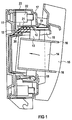
- the fuse switch disconnector shown in FIG 1 exists essentially from a lower part 11 with receiving contacts 12 for safety knife 13 of low-voltage high-performance fuses 14, a cover which can be snapped onto the lower part 11 17 and a fuse holder 15 that holds the low voltage high power fuses 14 carries over holding flags 16.
- the fuse holder 15 is with the lower part 11 via Known rotary joint not shown connected.
- the Cover 17 covers the receiving contacts 12 and thus serves as protection against contact.
- Way slots 18 introduced for inserting the safety knife 13.
- At the swivel joint for the fuse holder 15 facing away from the cover 17 is provided with chambers 19, into each of the receiving contacts 12, i.e. a Fixed contact is made for each phase.
- the fuse switch disconnector 1 is in a position during the switch-on process shown shortly after swinging open the Fuse holder 15 in which the fuse knife 13 the contacts Touch 12.
- Arrows 20 show the spread of Metal vapors and ionized gases indicated. These will held by a wall 21 associated with chamber 19 and reflected.
- the wall 21 lies on the safety knife 13 opposite side of the receiving contact 12.
- the chamber 19 encloses the receiving contact 12 on all sides by walls, wherein only one of the walls through the slot 18 for contacting of the safety knife 13 with the receiving contact 12 is interrupted. Down, i.e. to the lower part 11 the chamber 12 opened, thereby causing the explosive A targeted spread of metal vapors and gases To offer pressure relief and to derive this.
- the Wall 21 of the chamber 19 provides a partition to the terminal 22 out, which has a connection opening 23 on the Housing outer wall is accessible.
- FIG. 2 shows a fuse switch disconnector according to the invention Type shown without a fuse holder and fuses.
- the connector 22 for connecting a cable lug formed by a wide connection opening 23 in the Housing outer wall is insertable. Without the design of the Cover 17 with individual chambers 19 and the associated ones Walls 21 would contain the metal vapors and ionized gases spread outward unhindered towards the connection opening 23 can and thereby the risk of short circuit significantly enlarge. Otherwise, the same reference numerals as in 1 used because the embodiment is basically the same is trained.
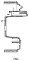
- FIG. 4 shows the cover 17 in a bottom view, i.e. out the view of the lower part 11.
- the three individual ones Chambers 19 can be seen for each phase. These are each through the walls 21 and adjoining transverse walls 24 formed that the receiving contact 12 on all sides except for the Surround slot 18.
- the transverse walls 24 also serve as Partitions between adjacent receptacle contacts 12.
Landscapes
- Fuses (AREA)
- Emergency Protection Circuit Devices (AREA)
- Arc-Extinguishing Devices That Are Switches (AREA)
- Electrophonic Musical Instruments (AREA)
- Gas-Insulated Switchgears (AREA)
Abstract
Beim Zuschalten eines Sicherungstrennschalters auf einen Kurzschluß bildet sich ein Lichtbogen, der mit einer explosionsartigen Ausbreitung von Metalldämpfen und ionisierten Gasen verbunden ist. Ein schädigender Einfluß hierdurch, insbesondere die Verursachung eines Kurzschlusses, soll vermieden werden. Hierzu ist die Abdeckung (17) des Sicherungstrennschlalters mit Kammern (19) zur Aufnahme der Festkontaktteile (12) versehen, die somit allseitig, bis auf den Aufnahmeschlitz (18) zur Kontaktierung mit den Messern (13) der Sicherungen (14), gekapselt sind. Lediglich zum Unterteil (11) hin sind die Kammern (19) geöffnet, um eine Druckentlastung und Ausbreitung für die Metalldämpfe und Gase zu ermöglichen. <IMAGE>When a fuse switch is switched on for a short circuit, an arc is formed which is associated with an explosive spread of metal vapors and ionized gases. A damaging influence, in particular the cause of a short circuit, should be avoided. For this purpose, the cover (17) of the fuse disconnector is provided with chambers (19) for receiving the fixed contact parts (12), which are encapsulated on all sides except for the receiving slot (18) for contacting the knives (13) of the fuses (14) . The chambers (19) are only open towards the lower part (11) in order to allow pressure relief and expansion for the metal vapors and gases. <IMAGE>
Description
Die Erfindung bezieht sich auf einen Sicherungstrennschalter mit einem Unterteil, das Festkontaktteile aufweist, mit einer Abdeckung für das Unterteil und mit einem Sicherungshalter mit Sicherungen zur Kontaktierung der Festkontaktteile.The invention relates to a fuse disconnector with a lower part, which has fixed contact parts, with a Cover for the lower part and with a fuse holder with fuses for contacting the fixed contact parts.
Ein gattungsgemäßer Sicherungstrennschalter ist aus der
DE-GM 92 08 693.4 bekannt. Dieser Sicherungstrennschalter gemäß
FIG 5 besteht aus einem Unterteil 1 mit den Aufnabmekontakten
2 für die Messer 3 von Niederspannungs-Hochleistungssicherungen
4. Die Niederspannungs-Hochleistungssicherungen 4
sind in einem Sicherungshalter 5 über Haltefahnen 6 gehalten.
Der Sicherungshalter 5 ist mit dem Unterteil 1 über ein nicht
näher dargestelltes Drehgelenk verbunden. Die Aufnahmekontakte
2 sind von einer Abdeckung 7 abgedeckt. In der Abdeckung
7 sind Schlitze 8 zum Einführen der Messer 3 eingebracht.
An der dem Drehgelenk für den Sicherungshalter abgewandten
Seite ist die Abdeckung 7 mit einer nach außen geschlossenen,
schlitzförmigen Lichtbogenführung 9 ausgestattet,
die eine Austrittsöffnung 10 besitzt.A generic fuse switch is from the
DE-GM 92 08 693.4 known. This fuse switch according to
5 consists of a
Beim Öffnen des Sicherungstrennschalter wird der Sicherungshalter
5 vom Unterteil 1 getrennt, indem unter Drehung des
Sicherungshalters 5 die Kontaktmesser 3 aus den Aufnahmekontakten
2 herausgezogen werden. Der entstehende Lichtbogen
tritt in die schlitzförmige Lichtbogenführung 9 ein. Ein Teil
tritt aus der Austrittsöffnung 10 heraus, ein anderer Teil
wird in Lichtbogenumlenkkammern hineingelenkt.When the fuse disconnector is opened, the
Diese Lichtbogenlöscheinrichtung dient zum Ausschalten von Lastströmen. Die Lastströme sind mit Scheitelwerten von ca. 1 kA relativ gering. Die dabei auftretenden Lichtbogen stehen ca. 10 bis 20 ms, d.h. relativ lange an. Die Problemzone beim Ausschalten von Lastströmen liegt vor dem Kontaktstück, weswegen in diesem Bereich zur Lösung des Problems Lichtbogenumlenkkammern mit der Austrittsöffnung 10 vorgesehen sind.This arc quenching device is used to switch off Load currents. The load currents are with peak values of approx. 1 kA relatively low. The arcing that occurs is stopped approx. 10 to 20 ms, i.e. relatively long. The problem area with Switching off load currents lies in front of the contact piece, which is why in this area to solve the problem of arc deflection chambers are provided with the outlet opening 10.
Zur Beherrschung hoher Kurzschlußströme beim Einschalten des Sicherungstrennschalters sind bisher keine besonderen technischen Maßnahmen bekannt. Die beim Einschalten auf einen Kurzschluß auftretenden Kurzschlußströme werden vor Erreichen ihrer Scheitelwerte von ca. 100 kA bereits nach relativ kurzer Dauer (ca. 1 ms) durch die Sicherungen abgeschaltet. Die hohe Stromsteilheit führt hierbei zu einer explosionsartigen Ausbreitung von Metalldämpfen und ionisierten Gasen nach allen Richtungen um den Lichtbogen. Die Problemzone liegt hier im Bereich des Kontaktstücks, d.h. unterhalb der für das Ausschalten relevanten Problemzone. Aufgrund der Metalldämpfe und ionisierten Gase ist ohne besondere Vorkehrungen ein Phasenüberschlag zwischen nebeneinander liegenden Kontaktstücken möglich. Weist das Gehäuse verhältnismäßig große Anschlußöffnungen für die Aufnahmekontakte auf und liegen diese frei, so ist nicht auszuschließen, daß die Metalldämpfe vom Aufnahmekontakt durch die Anschlußöffnung nach außen treten und es bei Befestigung des Sicherungstrennschalters auf einer geerdeten Befestigungsplatte mit dieser zu einem Kurzschluß kommt.To control high short-circuit currents when switching on the Fuse disconnectors are not yet any special technical ones Measures known. The when switching on for a short circuit occurring short circuit currents are before reaching their Peak values of approx. 100 kA after a relatively short time Duration (approx. 1 ms) switched off by the fuses. The height Current steepness leads to an explosion-like spread of metal vapors and ionized gases after all Directions around the arc. The problem area is here Area of the contact piece, i.e. below that for turning off relevant problem area. Because of the metal fumes and ionized gases is without any special precautions Phase overturn between adjacent contact pieces possible. The housing has relatively large connection openings for the receiving contacts and these are free, it cannot be ruled out that the metal vapors from Push the receiving contact out through the connection opening and it when mounting the fuse switch on a grounded mounting plate with this to a short circuit is coming.
Daher liegt der Erfindung die Aufgabe zugrunde, einen Sicherungstrennschalter der obengenannten Art dahingehend zu verbessern, daß eine schädigende Beeinflussung durch beim Einschalten auf einen Kurzschluß auftretende Metalldämpfe und ionisierte Gase vermieden wird.The invention is therefore based on the object of a fuse disconnector of the above kind to improve that a damaging influence by turning on on a short circuit occurring metal vapors and ionized gases is avoided.
Die Aufgabe wird dadurch gelöst, daß in die Abdeckung Kammern zur Aufnahme der Festkontaktteile integriert sind, daß Trennwände der Kammern nebeneinander liegende Festkontaktteile gegenseitig abschotten und daß die Kammern jeweils auf der der jeweiligen Sicherung abgewandten Seite eine Wand aufweisen. The object is achieved in that chambers in the cover integrated for receiving the fixed contact parts that partitions the chambers fixed contact parts lying next to each other isolate and that the chambers each on the have a wall facing away from the respective fuse.
Eine besonders vorteilhafte Ausführung der Erfindung besteht, wenn die Kammer auf der dem Unterteil zugewandten Seite geöffnet ist, wodurch eine gezielte Druckentlastung und eine Ableitung der ionisierten Gase und Metalldämpfe ermöglicht wird.A particularly advantageous embodiment of the invention consists of when the chamber opens on the side facing the lower part is, whereby a targeted pressure relief and a Allows the ionized gases and metal vapors to be discharged becomes.
Ein Ausführungsbeispiel der Erfindung wird im folgenden anhand einer Zeichnung näher erläutert. Es zeigen:
- FIG 1
- eine Schnittdarstellung eines erfindungsgemäßen Sicherungslasttrennschalters,
- FIG 2
- einen erfindungsgemäßen Sicherungslasttrennschalter ohne Deckelteil und Sicherungen,
- FIG 3
- eine Abdeckung für Anschlüsse und Kontakte eines Sicherungslasttrennschalters in einer Querschnittsdarstellung,
- FIG 4
- eine Unteransicht der Abdeckung gemäß FIG 3 und
- FIG 5
- eine Schnittdarstellung eines bekannten Sicherungslasttrennschalters.
- FIG. 1
- 2 shows a sectional illustration of a fuse switch disconnector according to the invention,
- FIG 2
- a fuse switch disconnector according to the invention without cover part and fuses,
- FIG 3
- a cover for connections and contacts of a fuse switch disconnector in a cross-sectional view,
- FIG 4
- a bottom view of the cover of FIG 3 and
- FIG 5
- a sectional view of a known fuse switch disconnector.
Der in FIG 1 dargestellte Sicherungslasttrennschalter besteht
im wesentlichen aus einem Unterteil 11 mit Aufnahmekontakten
12 für Sicherungsmesser 13 von Niederspannungs-Hochleistungssicherungen
14, einer auf das Unterteil 11 aufrastbaren Abdeckung
17 und einem Sicherungshalter 15, der die Niederspannungs-Hochleistungssicherungen
14 über Haltefahnen 16 trägt.
Der Sicherungshalter 15 ist mit dem Unterteil 11 über ein
nicht näher dargestelltes bekanntes Drehgelenk verbunden. Die
Abdeckung 17 deckt die Aufnahmekontakte 12 ab und dient somit
als Berührungsschutz. In der Abdeckung 17 sind in bekannter
Weise Schlitze 18 zum Einführen der Sicherungsmesser 13 eingebracht.
An der dem Drehgelenk für den Sicherungshalter 15
abgewandten Seite ist die Abdeckung 17 mit Kammern 19 versehen,
in die jeweils einer der Aufnahmekontakte 12, d.h. ein
Festkontakt für jede Phase aufgenommen ist. Der Sicherungslasttrennschalter
ist in FIG 1 in einer Position beim Einschaltvorgang
dargestellt, kurz nach dem Aufschwenken des
Sicherungshalters 15 in dem die Sicherungsmesser 13 die Kontakte
12 berühren. Durch Pfeile 20 ist die Ausbreitung von
Metalldämpfen und ionisierten Gasen angedeutet. Diese werden
von einer zur Kammer 19 zugehörigen Wand 21 abgehalten und
reflektiert. Die Wand 21 liegt auf der dem Sicherungsmesser
13 abgewandten Seite des Aufnahmekontaktes 12. Die Kammer 19
umschließt den Aufnahmekontakt 12 allseitig durch Wände, wobei
lediglich eine der Wände durch den Schlitz 18 zur Kontaktierung
des Sicherungsmessers 13 mit dem Aufnahmekontakt 12
unterbrochen ist. Nach unten, d.h. zum Unterteil 11 hin ist
die Kammer 12 geöffnet, um hierdurch bei der explosionsartigen
Ausbreitung der Metalldämpfe und Gase eine gezielte
Druckentlastung zu bieten und diese hierüber abzuleiten. Die
Wand 21 der Kammer 19 stellt eine Abschottung zur Anschlußklemme
22 hin dar, die über eine Anschlußöffnung 23 an der
Gehäuseaußenwand zugänglich ist. Für jede Phase existiert
eine eigene Kammer 19, d.h. nebeneinander liegende Aufnahmekontakte
12 der drei Phasen sind untereinander durch hier
nicht dargestellte Trennwände ebenfalls abgeschottet.The fuse switch disconnector shown in FIG 1 exists
essentially from a
In FIG 2 ist ein Sicherungslasttrennschalter erfindungsgemäßer
Art ohne einen Sicherungshalter und Sicherungen dargestellt.
Abweichend zu der in FIG 1 gezeigten Ausführungsform
ist hier die Anschlußklemme 22 zum Anschluß eines Kabelschuhs
ausgebildet, der durch eine weite Anschlußöffnung 23 in der
Gehäuseaußenwand einführbar ist. Ohne die Ausgestaltung der
Abdeckung 17 mit einzelnen Kammern 19 und den hier zugehörigen
Wänden 21 würden die Metalldämpfe und ionisierten Gase
sich ungehindert zur Anschlußöffnung 23 hin nach außen ausbreiten
können und hierdurch die Kurzschlußgefahr erheblich
vergrößern. Im übrigen sind hier gleiche Bezugszeichen wie in
FIG 1 verwendet, da die Ausführungsform grundsätzlich gleich
ausgebildet ist.2 shows a fuse switch disconnector according to the invention
Type shown without a fuse holder and fuses.
Deviating from the embodiment shown in FIG. 1
here is the
In FIG 3 ist die Abdeckung 17 dargestellt, die den Aufnahmebereich
der Kammer 19 für einen Aufnahmekontakt 12 deutlich
wiedergibt. In Figure 3, the
FIG 4 zeigt die Abdeckung 17 in einer Unteransicht, d.h. aus
der Sicht des Unterteils 11. Hier sind die drei einzelnen
Kammern 19 für jede Phase ersichtlich. Diese werden jeweils
durch die Wände 21 und sich daran anschließende Querwände 24
gebildet, die den Aufnahmekontakt 12 allseitig bis auf den
Aufnahmeschlitz 18 umgeben. Die Querwände 24 dienen auch als
Trennwände zwischen benachbarten Aufnahmekontakten 12. Durch
diese Kapselung der Aufnahmekontakte 12 wird eine Wanderung
des Lichtbogens zu benachbarten Aufnahmekontakten und damit
eine Kurzschlußbildung verhindert.4 shows the
Claims (2)
Applications Claiming Priority (2)
| Application Number | Priority Date | Filing Date | Title |
|---|---|---|---|
| DE29804247U | 1998-03-10 | ||
| DE29804247U DE29804247U1 (en) | 1998-03-10 | 1998-03-10 | Fuse disconnector |
Publications (3)
| Publication Number | Publication Date |
|---|---|
| EP0942448A2 true EP0942448A2 (en) | 1999-09-15 |
| EP0942448A3 EP0942448A3 (en) | 2000-01-05 |
| EP0942448B1 EP0942448B1 (en) | 2007-08-08 |
Family
ID=8053909
Family Applications (1)
| Application Number | Title | Priority Date | Filing Date |
|---|---|---|---|
| EP99103698A Expired - Lifetime EP0942448B1 (en) | 1998-03-10 | 1999-02-25 | Isolating switch with fuses |
Country Status (3)
| Country | Link |
|---|---|
| EP (1) | EP0942448B1 (en) |
| AT (1) | ATE369613T1 (en) |
| DE (2) | DE29804247U1 (en) |
Families Citing this family (5)
| Publication number | Priority date | Publication date | Assignee | Title |
|---|---|---|---|---|
| FR2811812B1 (en) * | 2000-07-12 | 2003-06-27 | Mecelec Ind | CONNECTION CONNECTOR AND ELECTRICAL CONNECTION ASSEMBLY BETWEEN A SET OF BARS AND AT LEAST ONE CONDUCTIVE CABLE |
| EP1903589B1 (en) * | 2006-09-21 | 2014-10-01 | Siemens Aktiengesellschaft | Safety circuit breaker with light arc chamber |
| CN100562960C (en) * | 2006-10-11 | 2009-11-25 | 上海华通电气有限公司 | isolating switch fuse group |
| DE102009033541A1 (en) * | 2009-07-14 | 2011-01-20 | Siemens Aktiengesellschaft | Multipolar electrical switch, particularly fuse-switch for use in switch box, e.g. busbar trunking tap-unit, has multiple switching modules which are modularly assembled |
| CN111816490A (en) * | 2020-07-31 | 2020-10-23 | 重庆德普电气有限公司 | Outdoor low voltage enclosed load disconnect switch |
Family Cites Families (8)
| Publication number | Priority date | Publication date | Assignee | Title |
|---|---|---|---|---|
| DE1899474U (en) * | 1964-05-22 | 1964-08-27 | Leopold Neu | MULTI-PART FUSE PART, IN PARTICULAR FOR FUSE DISCONNECTORS AND FUSE DISCONNECTORS. |
| DE6939831U (en) * | 1969-10-14 | 1971-03-25 | Siemens Ag | MULTI-PHASE SWITCH-DISCONNECTOR. |
| DE2401030A1 (en) | 1974-01-10 | 1975-07-17 | Leopold Neu | Protective cover-cap for protruding spring-contact arms - has lateral tag at rim screwed to support plate |
| DE2544251B2 (en) * | 1975-10-03 | 1980-07-03 | Efen Elektrotechnische Fabrik Otto Frees Kg, 6229 Rauenthal | Low-voltage, high-performance fuse switch disconnectors |
| DE3918816C2 (en) * | 1989-06-09 | 1997-04-24 | Efen Elektrotech Fab | Cover for NH fuse strips or lower parts |
| DE9208693U1 (en) | 1992-06-29 | 1993-10-28 | Siemens AG, 80333 München | Fuse disconnector |
| DE9309654U1 (en) | 1993-06-29 | 1993-09-02 | Siemens AG, 80333 München | Fuse disconnector |
| DE9404155U1 (en) | 1994-03-11 | 1994-04-28 | Siemens AG, 80333 München | Fuse disconnector |
-
1998
- 1998-03-10 DE DE29804247U patent/DE29804247U1/en not_active Expired - Lifetime
-
1999
- 1999-02-25 AT AT99103698T patent/ATE369613T1/en not_active IP Right Cessation
- 1999-02-25 DE DE59914440T patent/DE59914440D1/en not_active Expired - Fee Related
- 1999-02-25 EP EP99103698A patent/EP0942448B1/en not_active Expired - Lifetime
Also Published As
| Publication number | Publication date |
|---|---|
| EP0942448B1 (en) | 2007-08-08 |
| DE29804247U1 (en) | 1998-05-07 |
| EP0942448A3 (en) | 2000-01-05 |
| DE59914440D1 (en) | 2007-09-20 |
| ATE369613T1 (en) | 2007-08-15 |
Similar Documents
| Publication | Publication Date | Title |
|---|---|---|
| DE69029697T2 (en) | Current limiting circuit breaker | |
| WO2005062333A1 (en) | Switching device | |
| EP0752153A1 (en) | Arc quenching chamber with three barriers for the passage of arc gasses | |
| EP0309386B1 (en) | Multi-pole low-voltage circuit breaker with an insulating case and an arc quencher | |
| EP1032942B1 (en) | Switching device with an electric arc extinguishing device | |
| EP0992049A1 (en) | Electromagnetic switching device with arcing chambers | |
| EP0942448A2 (en) | Isolating switch with fuses | |
| EP0251160A2 (en) | Quenching device for electric circuit breaker | |
| WO2002007175A1 (en) | Arc extinguisher with an attachment for low voltage switchgear | |
| DE3620416C2 (en) | ||
| EP1366501B1 (en) | Low-voltage circuit breaker with an electric arc extinction system | |
| DE3443122A1 (en) | DEVICE FOR INTERRUPTING CIRCUITS | |
| DE2720220A1 (en) | Fuse panel with double row of contact elements - accommodates one or more cassettes each carrying several fuses engaging pairs of contacts | |
| WO1999033080A1 (en) | Arc extinguisher for switchgear | |
| DE3019925C2 (en) | NH fuse disconnectors and load switches | |
| DE4243537A1 (en) | Procedure for switching a fuse switch disconnector and fuse switch disconnector therefor | |
| DE69309174T2 (en) | Circuit breaker with two concentric isolating chambers | |
| DE29905214U1 (en) | Arc quenching device | |
| EP0849758A2 (en) | Installation switch | |
| EP0231733A2 (en) | Arc quenching chamber | |
| EP0681737B1 (en) | Extinguishing stack for an arc extinguishing chamber | |
| EP0432859B1 (en) | Contact device for detachably receiving multipole switchgear break contacts | |
| EP0168568B1 (en) | Isolating switch, in particular a pantograph isolating switch | |
| DE2542434A1 (en) | Ring main switching unit with spur - consists of two on-load isolators which are bridged by off load isolator and is fitted with fuses | |
| DE1665377C2 (en) | Low voltage distribution |
Legal Events
| Date | Code | Title | Description |
|---|---|---|---|
| PUAI | Public reference made under article 153(3) epc to a published international application that has entered the european phase |
Free format text: ORIGINAL CODE: 0009012 |
|
| AK | Designated contracting states |
Kind code of ref document: A2 Designated state(s): AT CH DE FR LI NL |
|
| AX | Request for extension of the european patent |
Free format text: AL;LT;LV;MK;RO;SI |
|
| PUAL | Search report despatched |
Free format text: ORIGINAL CODE: 0009013 |
|
| AK | Designated contracting states |
Kind code of ref document: A3 Designated state(s): AT BE CH CY DE DK ES FI FR GB GR IE IT LI LU MC NL PT SE |
|
| AX | Request for extension of the european patent |
Free format text: AL;LT;LV;MK;RO;SI |
|
| 17P | Request for examination filed |
Effective date: 20000131 |
|
| AKX | Designation fees paid |
Free format text: AT CH DE FR LI NL |
|
| GRAP | Despatch of communication of intention to grant a patent |
Free format text: ORIGINAL CODE: EPIDOSNIGR1 |
|
| GRAS | Grant fee paid |
Free format text: ORIGINAL CODE: EPIDOSNIGR3 |
|
| GRAA | (expected) grant |
Free format text: ORIGINAL CODE: 0009210 |
|
| AK | Designated contracting states |
Kind code of ref document: B1 Designated state(s): AT CH DE FR LI NL |
|
| REG | Reference to a national code |
Ref country code: CH Ref legal event code: EP |
|
| REF | Corresponds to: |
Ref document number: 59914440 Country of ref document: DE Date of ref document: 20070920 Kind code of ref document: P |
|
| PG25 | Lapsed in a contracting state [announced via postgrant information from national office to epo] |
Ref country code: NL Free format text: LAPSE BECAUSE OF FAILURE TO SUBMIT A TRANSLATION OF THE DESCRIPTION OR TO PAY THE FEE WITHIN THE PRESCRIBED TIME-LIMIT Effective date: 20070808 |
|
| NLV1 | Nl: lapsed or annulled due to failure to fulfill the requirements of art. 29p and 29m of the patents act | ||
| ET | Fr: translation filed | ||
| PLBE | No opposition filed within time limit |
Free format text: ORIGINAL CODE: 0009261 |
|
| STAA | Information on the status of an ep patent application or granted ep patent |
Free format text: STATUS: NO OPPOSITION FILED WITHIN TIME LIMIT |
|
| 26N | No opposition filed |
Effective date: 20080509 |
|
| PGFP | Annual fee paid to national office [announced via postgrant information from national office to epo] |
Ref country code: FR Payment date: 20080214 Year of fee payment: 10 Ref country code: DE Payment date: 20080410 Year of fee payment: 10 |
|
| REG | Reference to a national code |
Ref country code: CH Ref legal event code: PL |
|
| PG25 | Lapsed in a contracting state [announced via postgrant information from national office to epo] |
Ref country code: LI Free format text: LAPSE BECAUSE OF NON-PAYMENT OF DUE FEES Effective date: 20080229 Ref country code: CH Free format text: LAPSE BECAUSE OF NON-PAYMENT OF DUE FEES Effective date: 20080229 |
|
| PG25 | Lapsed in a contracting state [announced via postgrant information from national office to epo] |
Ref country code: AT Free format text: LAPSE BECAUSE OF NON-PAYMENT OF DUE FEES Effective date: 20080225 |
|
| REG | Reference to a national code |
Ref country code: FR Ref legal event code: ST Effective date: 20091030 |
|
| PG25 | Lapsed in a contracting state [announced via postgrant information from national office to epo] |
Ref country code: DE Free format text: LAPSE BECAUSE OF NON-PAYMENT OF DUE FEES Effective date: 20090901 |
|
| PG25 | Lapsed in a contracting state [announced via postgrant information from national office to epo] |
Ref country code: FR Free format text: LAPSE BECAUSE OF NON-PAYMENT OF DUE FEES Effective date: 20090302 |