EP0942448A2 - Sectionneur à fusibles - Google Patents
Sectionneur à fusibles Download PDFInfo
- Publication number
- EP0942448A2 EP0942448A2 EP99103698A EP99103698A EP0942448A2 EP 0942448 A2 EP0942448 A2 EP 0942448A2 EP 99103698 A EP99103698 A EP 99103698A EP 99103698 A EP99103698 A EP 99103698A EP 0942448 A2 EP0942448 A2 EP 0942448A2
- Authority
- EP
- European Patent Office
- Prior art keywords
- fuse
- chambers
- cover
- fuses
- receiving
- Prior art date
- Legal status (The legal status is an assumption and is not a legal conclusion. Google has not performed a legal analysis and makes no representation as to the accuracy of the status listed.)
- Granted
Links
Images


Classifications
-
- H—ELECTRICITY
- H01—ELECTRIC ELEMENTS
- H01H—ELECTRIC SWITCHES; RELAYS; SELECTORS; EMERGENCY PROTECTIVE DEVICES
- H01H31/00—Air-break switches for high tension without arc-extinguishing or arc-preventing means
- H01H31/02—Details
- H01H31/12—Adaptation for built-in fuse
- H01H31/122—Fuses mounted on, or constituting the movable contact parts of, the switch
-
- H—ELECTRICITY
- H01—ELECTRIC ELEMENTS
- H01H—ELECTRIC SWITCHES; RELAYS; SELECTORS; EMERGENCY PROTECTIVE DEVICES
- H01H9/00—Details of switching devices, not covered by groups H01H1/00 - H01H7/00
- H01H9/30—Means for extinguishing or preventing arc between current-carrying parts
- H01H9/34—Stationary parts for restricting or subdividing the arc, e.g. barrier plate
- H01H9/342—Venting arrangements for arc chutes
Definitions
- the invention relates to a fuse disconnector with a lower part, which has fixed contact parts, with a Cover for the lower part and with a fuse holder with fuses for contacting the fixed contact parts.
- a generic fuse switch is from the DE-GM 92 08 693.4 known.
- This fuse switch according to 5 consists of a lower part 1 with the receptacle contacts 2 for the knives 3 of low-voltage high-performance fuses 4.
- the low-voltage high-performance fuses 4 are held in a fuse holder 5 via holding tabs 6.
- the fuse holder 5 is not with the lower part 1 connected pivot joint shown.
- the recording contacts 2 are covered by a cover 7.
- slots 8 are introduced for inserting the knife 3.
- On the side facing away from the swivel joint for the fuse holder Side is the cover 7 with a closed to the outside, slot-shaped arc guide 9 equipped, which has an outlet opening 10.
- This arc quenching device is used to switch off Load currents.
- the load currents are with peak values of approx. 1 kA relatively low.
- the arcing that occurs is stopped approx. 10 to 20 ms, i.e. relatively long.
- the problem area with Switching off load currents lies in front of the contact piece, which is why in this area to solve the problem of arc deflection chambers are provided with the outlet opening 10.
- the invention is therefore based on the object of a fuse disconnector of the above kind to improve that a damaging influence by turning on on a short circuit occurring metal vapors and ionized gases is avoided.
- the object is achieved in that chambers in the cover integrated for receiving the fixed contact parts that partitions the chambers fixed contact parts lying next to each other isolate and that the chambers each on the have a wall facing away from the respective fuse.
- a particularly advantageous embodiment of the invention consists of when the chamber opens on the side facing the lower part is, whereby a targeted pressure relief and a Allows the ionized gases and metal vapors to be discharged becomes.
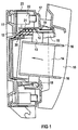
- the fuse switch disconnector shown in FIG 1 exists essentially from a lower part 11 with receiving contacts 12 for safety knife 13 of low-voltage high-performance fuses 14, a cover which can be snapped onto the lower part 11 17 and a fuse holder 15 that holds the low voltage high power fuses 14 carries over holding flags 16.
- the fuse holder 15 is with the lower part 11 via Known rotary joint not shown connected.
- the Cover 17 covers the receiving contacts 12 and thus serves as protection against contact.
- Way slots 18 introduced for inserting the safety knife 13.
- At the swivel joint for the fuse holder 15 facing away from the cover 17 is provided with chambers 19, into each of the receiving contacts 12, i.e. a Fixed contact is made for each phase.
- the fuse switch disconnector 1 is in a position during the switch-on process shown shortly after swinging open the Fuse holder 15 in which the fuse knife 13 the contacts Touch 12.
- Arrows 20 show the spread of Metal vapors and ionized gases indicated. These will held by a wall 21 associated with chamber 19 and reflected.
- the wall 21 lies on the safety knife 13 opposite side of the receiving contact 12.
- the chamber 19 encloses the receiving contact 12 on all sides by walls, wherein only one of the walls through the slot 18 for contacting of the safety knife 13 with the receiving contact 12 is interrupted. Down, i.e. to the lower part 11 the chamber 12 opened, thereby causing the explosive A targeted spread of metal vapors and gases To offer pressure relief and to derive this.
- the Wall 21 of the chamber 19 provides a partition to the terminal 22 out, which has a connection opening 23 on the Housing outer wall is accessible.
- FIG. 2 shows a fuse switch disconnector according to the invention Type shown without a fuse holder and fuses.
- the connector 22 for connecting a cable lug formed by a wide connection opening 23 in the Housing outer wall is insertable. Without the design of the Cover 17 with individual chambers 19 and the associated ones Walls 21 would contain the metal vapors and ionized gases spread outward unhindered towards the connection opening 23 can and thereby the risk of short circuit significantly enlarge. Otherwise, the same reference numerals as in 1 used because the embodiment is basically the same is trained.
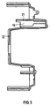
- FIG. 4 shows the cover 17 in a bottom view, i.e. out the view of the lower part 11.
- the three individual ones Chambers 19 can be seen for each phase. These are each through the walls 21 and adjoining transverse walls 24 formed that the receiving contact 12 on all sides except for the Surround slot 18.
- the transverse walls 24 also serve as Partitions between adjacent receptacle contacts 12.
Landscapes
- Fuses (AREA)
- Emergency Protection Circuit Devices (AREA)
- Arc-Extinguishing Devices That Are Switches (AREA)
- Electrophonic Musical Instruments (AREA)
- Gas-Insulated Switchgears (AREA)
Applications Claiming Priority (2)
| Application Number | Priority Date | Filing Date | Title |
|---|---|---|---|
| DE29804247U DE29804247U1 (de) | 1998-03-10 | 1998-03-10 | Sicherungstrennschalter |
| DE29804247U | 1998-03-10 |
Publications (3)
| Publication Number | Publication Date |
|---|---|
| EP0942448A2 true EP0942448A2 (fr) | 1999-09-15 |
| EP0942448A3 EP0942448A3 (fr) | 2000-01-05 |
| EP0942448B1 EP0942448B1 (fr) | 2007-08-08 |
Family
ID=8053909
Family Applications (1)
| Application Number | Title | Priority Date | Filing Date |
|---|---|---|---|
| EP99103698A Expired - Lifetime EP0942448B1 (fr) | 1998-03-10 | 1999-02-25 | Sectionneur à fusibles |
Country Status (3)
| Country | Link |
|---|---|
| EP (1) | EP0942448B1 (fr) |
| AT (1) | ATE369613T1 (fr) |
| DE (2) | DE29804247U1 (fr) |
Families Citing this family (5)
| Publication number | Priority date | Publication date | Assignee | Title |
|---|---|---|---|---|
| FR2811812B1 (fr) * | 2000-07-12 | 2003-06-27 | Mecelec Ind | Connecteur de raccordement et ensemble de raccordement electrique entre un jeu de barres et au moins un cable conducteur |
| EP1903589B1 (fr) * | 2006-09-21 | 2014-10-01 | Siemens Aktiengesellschaft | Sectionneur à coupure en charge de sécurité doté d'une boîte d'extinction d'arc |
| CN100562960C (zh) * | 2006-10-11 | 2009-11-25 | 上海华通电气有限公司 | 隔离开关熔断器组 |
| DE102009033541A1 (de) * | 2009-07-14 | 2011-01-20 | Siemens Aktiengesellschaft | Mehrpoliger elektrischer Schalter und Schaltkasten mit einem mehrpoligen elektrischen Schalter |
| CN111816490A (zh) * | 2020-07-31 | 2020-10-23 | 重庆德普电气有限公司 | 户外低压封闭式负荷隔离开关 |
Family Cites Families (8)
| Publication number | Priority date | Publication date | Assignee | Title |
|---|---|---|---|---|
| DE1899474U (de) * | 1964-05-22 | 1964-08-27 | Leopold Neu | Mehrteiliges sicherungsunterteil, insbesondere fuer sicherrungstrenner und sicherungslasttrenner. |
| DE6939831U (de) * | 1969-10-14 | 1971-03-25 | Siemens Ag | Mehrphasiger lasttrennschalter. |
| DE2401030A1 (de) | 1974-01-10 | 1975-07-17 | Leopold Neu | Halterung einer einteiligen beruehrungsschutzkappe an einem aufnahmekontakt |
| DE2544251B2 (de) * | 1975-10-03 | 1980-07-03 | Efen Elektrotechnische Fabrik Otto Frees Kg, 6229 Rauenthal | Niederspannungs-Hochleistungs-Sicherungslasttrenner |
| DE3918816C2 (de) * | 1989-06-09 | 1997-04-24 | Efen Elektrotech Fab | Abdeckung für NH-Sicherungsleisten oder -unterteile |
| DE9208693U1 (de) | 1992-06-29 | 1993-10-28 | Siemens AG, 80333 München | Sicherungstrennschalter |
| DE9309654U1 (de) | 1993-06-29 | 1993-09-02 | Siemens AG, 80333 München | Sicherungstrennschalter |
| DE9404155U1 (de) | 1994-03-11 | 1994-04-28 | Siemens AG, 80333 München | Sicherungstrennschalter |
-
1998
- 1998-03-10 DE DE29804247U patent/DE29804247U1/de not_active Expired - Lifetime
-
1999
- 1999-02-25 DE DE59914440T patent/DE59914440D1/de not_active Expired - Fee Related
- 1999-02-25 AT AT99103698T patent/ATE369613T1/de not_active IP Right Cessation
- 1999-02-25 EP EP99103698A patent/EP0942448B1/fr not_active Expired - Lifetime
Also Published As
| Publication number | Publication date |
|---|---|
| DE29804247U1 (de) | 1998-05-07 |
| DE59914440D1 (de) | 2007-09-20 |
| EP0942448B1 (fr) | 2007-08-08 |
| EP0942448A3 (fr) | 2000-01-05 |
| ATE369613T1 (de) | 2007-08-15 |
Similar Documents
| Publication | Publication Date | Title |
|---|---|---|
| DE69029697T2 (de) | Strombegrenzender Stromkreisunterbrecher | |
| DE69018432T2 (de) | Mehrpoliger Ausschalter mit einem allen Polen gemeinsamen Gasfilter. | |
| WO2005062333A1 (fr) | Commutateur | |
| WO1995026033A1 (fr) | Chambre d'extinction d'arc a trois barrieres de passage des gaz de l'arc | |
| EP0309386B1 (fr) | Disjoncteur multipolaire de puissance à basse tension avec un boîtier isolant et chambre d'extinction d'arc | |
| DE1788098B1 (de) | Mehrpoliger Selbstschalter | |
| EP1032942B1 (fr) | Appareil de distribution muni d'un dispositif d'extinction d'arc | |
| EP0992049A1 (fr) | Appareil de commutation electromagnetique avec chambres d'extinction | |
| EP0942448A2 (fr) | Sectionneur à fusibles | |
| EP0251160A2 (fr) | Dispositif d'extinction pour disjoncteurs électriques | |
| WO2002007175A1 (fr) | Dispositif extincteur d'arc equipe d'un element rapporte pour appareillage de commutation basse tension | |
| DE3620416C2 (fr) | ||
| EP1366501B1 (fr) | Interrupteur de puissance a basse tension, a systeme d'extinction d'arc electrique | |
| DE3443122A1 (de) | Vorrichtung zur unterbrechung von stromkreisen | |
| EP1042772A1 (fr) | Dispositif extincteur d'arc destine a un appareillage de connexion | |
| DE4243537B4 (de) | Verfahren zum Schalten eines Sicherungslasttrenners und Sicherungslasttrenner hierzu | |
| DE3019925C2 (de) | NH- Sicherungstrenner und -Lastschalter | |
| DE69309174T2 (de) | Leistungsschalter mit zwei konzentrischen Trennkammern | |
| DE29905214U1 (de) | Lichtbogen-Löscheinrichtung | |
| EP0849758A2 (fr) | Interrupteur d'installation | |
| EP0231733A2 (fr) | Chambre d'extinction d'arc | |
| EP0681737B1 (fr) | Paquet de plaques d'extinction pour une chambre d'extinction d'arc | |
| EP0432859B1 (fr) | Dispositif de contact apte à recevoir des contacts de coupure amovibles d'un appareil de commutation multipolaire | |
| DE2542434A1 (de) | Ringkabelfeld zum schalten eines versorgungsringes und eines abzweiges | |
| DE1665377C2 (de) | Niederspannungsverteilung |
Legal Events
| Date | Code | Title | Description |
|---|---|---|---|
| PUAI | Public reference made under article 153(3) epc to a published international application that has entered the european phase |
Free format text: ORIGINAL CODE: 0009012 |
|
| AK | Designated contracting states |
Kind code of ref document: A2 Designated state(s): AT CH DE FR LI NL |
|
| AX | Request for extension of the european patent |
Free format text: AL;LT;LV;MK;RO;SI |
|
| PUAL | Search report despatched |
Free format text: ORIGINAL CODE: 0009013 |
|
| AK | Designated contracting states |
Kind code of ref document: A3 Designated state(s): AT BE CH CY DE DK ES FI FR GB GR IE IT LI LU MC NL PT SE |
|
| AX | Request for extension of the european patent |
Free format text: AL;LT;LV;MK;RO;SI |
|
| 17P | Request for examination filed |
Effective date: 20000131 |
|
| AKX | Designation fees paid |
Free format text: AT CH DE FR LI NL |
|
| GRAP | Despatch of communication of intention to grant a patent |
Free format text: ORIGINAL CODE: EPIDOSNIGR1 |
|
| GRAS | Grant fee paid |
Free format text: ORIGINAL CODE: EPIDOSNIGR3 |
|
| GRAA | (expected) grant |
Free format text: ORIGINAL CODE: 0009210 |
|
| AK | Designated contracting states |
Kind code of ref document: B1 Designated state(s): AT CH DE FR LI NL |
|
| REG | Reference to a national code |
Ref country code: CH Ref legal event code: EP |
|
| REF | Corresponds to: |
Ref document number: 59914440 Country of ref document: DE Date of ref document: 20070920 Kind code of ref document: P |
|
| PG25 | Lapsed in a contracting state [announced via postgrant information from national office to epo] |
Ref country code: NL Free format text: LAPSE BECAUSE OF FAILURE TO SUBMIT A TRANSLATION OF THE DESCRIPTION OR TO PAY THE FEE WITHIN THE PRESCRIBED TIME-LIMIT Effective date: 20070808 |
|
| NLV1 | Nl: lapsed or annulled due to failure to fulfill the requirements of art. 29p and 29m of the patents act | ||
| ET | Fr: translation filed | ||
| PLBE | No opposition filed within time limit |
Free format text: ORIGINAL CODE: 0009261 |
|
| STAA | Information on the status of an ep patent application or granted ep patent |
Free format text: STATUS: NO OPPOSITION FILED WITHIN TIME LIMIT |
|
| 26N | No opposition filed |
Effective date: 20080509 |
|
| PGFP | Annual fee paid to national office [announced via postgrant information from national office to epo] |
Ref country code: FR Payment date: 20080214 Year of fee payment: 10 Ref country code: DE Payment date: 20080410 Year of fee payment: 10 |
|
| REG | Reference to a national code |
Ref country code: CH Ref legal event code: PL |
|
| PG25 | Lapsed in a contracting state [announced via postgrant information from national office to epo] |
Ref country code: LI Free format text: LAPSE BECAUSE OF NON-PAYMENT OF DUE FEES Effective date: 20080229 Ref country code: CH Free format text: LAPSE BECAUSE OF NON-PAYMENT OF DUE FEES Effective date: 20080229 |
|
| PG25 | Lapsed in a contracting state [announced via postgrant information from national office to epo] |
Ref country code: AT Free format text: LAPSE BECAUSE OF NON-PAYMENT OF DUE FEES Effective date: 20080225 |
|
| REG | Reference to a national code |
Ref country code: FR Ref legal event code: ST Effective date: 20091030 |
|
| PG25 | Lapsed in a contracting state [announced via postgrant information from national office to epo] |
Ref country code: DE Free format text: LAPSE BECAUSE OF NON-PAYMENT OF DUE FEES Effective date: 20090901 |
|
| PG25 | Lapsed in a contracting state [announced via postgrant information from national office to epo] |
Ref country code: FR Free format text: LAPSE BECAUSE OF NON-PAYMENT OF DUE FEES Effective date: 20090302 |