EP0941814A2 - Werkzeughandgriff - Google Patents
Werkzeughandgriff Download PDFInfo
- Publication number
- EP0941814A2 EP0941814A2 EP99104545A EP99104545A EP0941814A2 EP 0941814 A2 EP0941814 A2 EP 0941814A2 EP 99104545 A EP99104545 A EP 99104545A EP 99104545 A EP99104545 A EP 99104545A EP 0941814 A2 EP0941814 A2 EP 0941814A2
- Authority
- EP
- European Patent Office
- Prior art keywords
- tool handle
- base body
- handle according
- hand
- cap
- Prior art date
- Legal status (The legal status is an assumption and is not a legal conclusion. Google has not performed a legal analysis and makes no representation as to the accuracy of the status listed.)
- Withdrawn
Links
- 239000004033 plastic Substances 0.000 claims abstract description 24
- 229920003023 plastic Polymers 0.000 claims abstract description 24
- 230000007704 transition Effects 0.000 claims description 9
- 239000000463 material Substances 0.000 claims description 4
- 239000004952 Polyamide Substances 0.000 claims description 3
- 239000011324 bead Substances 0.000 claims description 3
- 229920002647 polyamide Polymers 0.000 claims description 3
- 239000004743 Polypropylene Substances 0.000 claims description 2
- 239000004676 acrylonitrile butadiene styrene Substances 0.000 claims description 2
- 229920000122 acrylonitrile butadiene styrene Polymers 0.000 claims description 2
- -1 polypropylene Polymers 0.000 claims description 2
- 229920001155 polypropylene Polymers 0.000 claims description 2
- 238000003860 storage Methods 0.000 claims description 2
- 210000003811 finger Anatomy 0.000 description 33
- 210000003813 thumb Anatomy 0.000 description 15
- 238000001746 injection moulding Methods 0.000 description 3
- 230000015572 biosynthetic process Effects 0.000 description 2
- 210000005224 forefinger Anatomy 0.000 description 2
- 230000000977 initiatory effect Effects 0.000 description 2
- 230000002093 peripheral effect Effects 0.000 description 2
- 238000005520 cutting process Methods 0.000 description 1
- 230000000694 effects Effects 0.000 description 1
- 230000003993 interaction Effects 0.000 description 1
- 230000007794 irritation Effects 0.000 description 1
- 238000004519 manufacturing process Methods 0.000 description 1
- 238000005096 rolling process Methods 0.000 description 1
- 210000000707 wrist Anatomy 0.000 description 1
Images
Classifications
-
- H—ELECTRICITY
- H01—ELECTRIC ELEMENTS
- H01R—ELECTRICALLY-CONDUCTIVE CONNECTIONS; STRUCTURAL ASSOCIATIONS OF A PLURALITY OF MUTUALLY-INSULATED ELECTRICAL CONNECTING ELEMENTS; COUPLING DEVICES; CURRENT COLLECTORS
- H01R43/00—Apparatus or processes specially adapted for manufacturing, assembling, maintaining, or repairing of line connectors or current collectors or for joining electric conductors
-
- B—PERFORMING OPERATIONS; TRANSPORTING
- B25—HAND TOOLS; PORTABLE POWER-DRIVEN TOOLS; MANIPULATORS
- B25G—HANDLES FOR HAND IMPLEMENTS
- B25G1/00—Handle constructions
- B25G1/04—Handle constructions telescopic; extensible; sectional
- B25G1/043—Handle constructions telescopic; extensible; sectional for screwdrivers, wrenches or spanners
- B25G1/046—Handle constructions telescopic; extensible; sectional for screwdrivers, wrenches or spanners with free-turning section at end of handle remote from tool
-
- B—PERFORMING OPERATIONS; TRANSPORTING
- B25—HAND TOOLS; PORTABLE POWER-DRIVEN TOOLS; MANIPULATORS
- B25G—HANDLES FOR HAND IMPLEMENTS
- B25G1/00—Handle constructions
- B25G1/10—Handle constructions characterised by material or shape
- B25G1/105—Handle constructions characterised by material or shape for screwdrivers, wrenches or spanners
-
- B—PERFORMING OPERATIONS; TRANSPORTING
- B25—HAND TOOLS; PORTABLE POWER-DRIVEN TOOLS; MANIPULATORS
- B25G—HANDLES FOR HAND IMPLEMENTS
- B25G1/00—Handle constructions
- B25G1/10—Handle constructions characterised by material or shape
- B25G1/12—Handle constructions characterised by material or shape electrically insulating material
- B25G1/125—Handle constructions characterised by material or shape electrically insulating material for screwdrivers, wrenches or spanners
-
- Y—GENERAL TAGGING OF NEW TECHNOLOGICAL DEVELOPMENTS; GENERAL TAGGING OF CROSS-SECTIONAL TECHNOLOGIES SPANNING OVER SEVERAL SECTIONS OF THE IPC; TECHNICAL SUBJECTS COVERED BY FORMER USPC CROSS-REFERENCE ART COLLECTIONS [XRACs] AND DIGESTS
- Y10—TECHNICAL SUBJECTS COVERED BY FORMER USPC
- Y10S—TECHNICAL SUBJECTS COVERED BY FORMER USPC CROSS-REFERENCE ART COLLECTIONS [XRACs] AND DIGESTS
- Y10S16/00—Miscellaneous hardware, e.g. bushing, carpet fastener, caster, door closer, panel hanger, attachable or adjunct handle, hinge, window sash balance
- Y10S16/902—Unitary handle composed of different cooperating materials
Definitions
- the present invention relates to: a tool handle, in particular for electronic screwdrivers, with a base made of hard plastic that holds the tool blade wearing and which is partially surrounded by a sheathing made of soft plastic.
- Handles of this type which are used in particular for various screwdrivers come and in this case are usually equipped with blades, the cutting width for slotted screws between 0.8 and 4 mm and which is a torque ratio of about 1:15, are characterized by a relatively small diameter, which enables sensitive work when tightening and loosening very small screws.
- the handle When quickly turning smooth-running screws, the handle is axially through the The tip of the index finger is supported in a dome-shaped form on the end of the handle The recess rests while the handle with the screwdriver blade inserted between Thumb and ring finger is turned. So that the interaction of the fingers this functional sequence is facilitated, the generic handles on hand-side end usually a rotatable cap with a front end dome-shaped depression.
- the tool handle is essentially cylindrical, a constricted area in the middle of the handle has and tapers in the shape of a truncated cone to the blade end.
- the constriction area has an octagonal cross-sectional profile.
- On the A rotatable cap is attached to the end of the handle body on the hand side.
- the handle is made entirely of hard plastic.
- Tool handle can preferably one or two elastic rings on the Constriction area can be slid on to keep your thumb and ring finger To bring turning to the plant.
- the rings bring no significant improvement the feel and function of the handle.
- Another tool handle for electronic screwdrivers also consists of Hard plastic and has an essentially slightly conical in its axial extent Shape with an octagonal cross-sectional profile. This cross-sectional profile is also due to an unfavorable contact position of the fingers disadvantageous when turning quickly of the tool handle.
- a tool handle for screwdrivers is known from EP 0 508 849, which is made of hard plastic and essentially consists of two grip areas, which each extend over half the length of the tool handle.
- the blade side Handle area is essentially cylindrical and has the circumference axially extending narrow grooves distributed at regular intervals on.
- the hand-side grip area is in relation to the blade-side grip area Enlarged 1: 1.5 in diameter.
- the transition between the blade side and the hand-side handle area is a truncated cone-shaped intermediate piece formed with a relatively large slope.
- the hand area of the handle wears at its free end a rotatable cap with a dome-shaped recess.
- a handle for a screwdriver is known, the base body consists of hard plastic and essentially as a rotationally symmetrical Body is formed.
- This known tool handle has one in the front Third of the tool handle arranged, thickened relative to the base body Force application zone in the form of truncated cones with their base surfaces on, on the lateral surfaces side by side handle pads made of soft plastic are trained. In front of the force application zone designed in this way is on the blade side a drive zone from the hard plastic base is formed.
- the hand end of this known tool handle is through formed a rotatably mounted on the base cap with a dome-shaped recess. Apart from the thickened force application zone, the grip is proportionate kept slim and has a substantially cylindrical cross-sectional shape.
- the present invention has for its object a tool handle type mentioned in such a way that the described disadvantages known Tool handles can be avoided.
- the tool handle is said to be both soulful Initiation of small moments and - with a different hand position - initiation of higher ones Torques without any particular tension on the hand enclosing the handle enable and provide a good feel with every hand position.
- the present invention provides a tool handle proposed with the features of claim 1.
- the fingers When holding the tool handle according to the invention on its blade side End between middle finger and thumb and abutments on one rotatable on the Base body mounted cap over the index finger, the fingers are for application of a torque on the concave surface so that the fingertips corresponding curvature results in a relatively large-area contact area. This is also covered by the soft plastic sheath, causing friction and the overall ease of use with such a bracket improved.
- the index finger lies on the cap. Because of the mounted on the base body There is no relative movement between the index finger and the tool handle.
- the thumb and index finger also enclose which is concave in the axial direction and has the sheathing made of soft plastic Surface of the tool handle.
- the torque can also be applied to this bracket in order to apply higher moments
- the tool handle according to the invention thus offers even when applying high moments when holding in the above mentioned type an improved compared to the known tool handles Ease of use.
- the tool handle according to the invention stands out the known handles through the ergonomically adapted functional areas out. It offers a good, pleasant facility for the fingertips and enables quick and sensitive turning of the handle.
- the tool handle according to the invention has three essential elements.
- a Element is the hand-sided, sheath-free section made of hard plastic, which is extends over approximately 3/5 of the longitudinal extent of the tool handle and in the longitudinal direction has a slightly convex contour.
- the cross-sectional profile of this section can be round or be out of round, in the latter case preferably six in the circumferential direction juxtaposed, slightly flattened areas extending in the longitudinal direction are trained.
- the handle preferably has at its handle end Cross hole on.
- the blade of the screwdriver is injected into the body of the tool handle.
- a holding device for interchangeable insert tools can also be used be provided.
- Another essential element of the tool handle according to the invention is a the base body in its blade-side area to about 2/5 of its total extent covering covering made of soft plastic provided on the base body of the tool handle is applied by injection molding or as a tubular, separately manufactured part connected to the base body in a non-positive or positive manner is.
- This covered area of the handle has a concave lengthwise direction Contour on.
- the concave region preferably has about 4/5 of its longitudinal extent a round cross-sectional profile.
- the concave contour in the longitudinal direction is designed so that the thumb and middle finger when turning quickly as well Find your thumb and index finger when turning at a higher torque. This also applies to different hand and finger lengths.
- the sheathing made of soft plastic not only forms a comfortable contact surface for the fingers, but also enables a very sensitive, non-slip turning.
- the tool handle according to the invention has a third element, which is formed by a rotatable cap at the hand end of the handle.
- This preferably has an axial bore on the handle side, which has an annular bore Undercut is provided.
- the base body preferably has a bearing pin on the one with the annular undercut kind of a snap connection cooperating annular collar carries.
- the Snap connection is designed and tolerated so that the cap is even under normal Axial load turns slightly on the handle.
- the diameter of the cap increases the end facing away from the handle is relatively strong.
- a dome-shaped centering recess is formed in the end face of the cap .
- the transitions of the outer contour in Longitudinal are well rounded. Due to the increased in diameter towards the end face Cap with the well rounded transitions will provide good support in the Hand palm reached.
- the enlarged diameter also enables Formation of a relatively large dome-shaped depression for safe Center the screwdriver between fingertip and screw.
- a slight twisting of the cap on the handle is achieved through precise adjustment of the tolerances between the trunnion and the bore in the cap that receives it causes.
- the shape and material design of the tool handle according to the invention offers a good, comfortable position for all three operating positions mentioned in the introduction Plant for the fingers and palms. It can be covered with soft plastic Section of the tool handle can be defined as a quick turning zone, whereas the hand-sided, sheathing-free section can be defined as a force application zone, in the high torques are initiated.
- the base body is however, it is concave in the area of the casing.
- the basic body of the Tool handle preferably shows at both ends of the casing Soft plastic ring grooves.
- the blade-side end of the Basic body the sheathing.
- the cross-sectional profile shows in the area of the blade over about 1/5 of the longitudinal extent of the casing at least two opposite Flattening on. These flattenings result in a relatively flat surface The tool handle rests on a flat surface and thus prevents an unwanted Roll away.
- the base body has a bearing journal on which the cap is rotatably mounted and by means of a snap connection to it is secured in the axial direction.
- a slight twist of the cap on the body is achieved by precisely matching the tolerances between the pins of the Base body and a hole in the cap receiving the pin.
- a thick-walled plastic injection molding, such as the cap is caused by the shrinkage a defined tolerance is possible. That is why around the hole in the cap centrically at least one annular recess in the form of a circular arc segment recessed. This reduces the wall thickness in this area so much that the shrinkage is low and the tolerance of the hole can be precisely defined.
- the base body and / or the cap made of a material with good running or Form storage properties, such as ABS, polypropylene, or polyamide similar plastics.
- the cap and the base body have at their transition area the same outside diameter.
- a contact surface for the fingers the peripheral surface of the cap is preferably formed in that the cap a extending from its blade-side end, concave in the axial direction Has curvature.
- the cap preferably has a convex curvature, which is in a dome-shaped depression, which according to Art centering is formed on the end face of the cap.
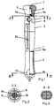
- Fig. 1 is an example of a tool handle in the form of a handle for one Electronics screwdriver shown.
- Tool blade carries a hand-side section 2, one in the longitudinal direction has convex surface. Between this section 2 and the blade side End of the base body 1, the base body 1 is concave in the longitudinal direction arched and surrounded by a casing 3.
- the hand-side section 2 has the hand-side at its hand-side end Section 2 outstanding, integrally connected to the base body 1 journal 4 on which a cap 5 is rotatably mounted.
- the cap 5 is via a snap connection connected to the pin 4.
- sleeve-like webs 5a are on the cap 5 formed, which are arranged concentrically to a bore 5b formed on the cap 5 are and with a formed on the pin 4 ring 4a like a Interact snap connection.
- the sleeve-like webs 5a are in the circumferential direction surrounded by circular segment-shaped recesses 6 which are wedge-shaped in the cap 5 taper and open to the base body 1.
- the radial direction outside the recesses 6 continues the material of the cap 5 and closes flush to the base body 1.
- the outside through corresponds Knife of the cap 5 at this transition area, the outer diameter of the base body 1.
- the cap 5 has one on its blade side End extending, axially concave curvature, which continues up to the largest diameter of the cap 5.
- the sheath-free, convex section 2 extends over approximately 3/5 of the longitudinal extent of the base body 1 and has a bore 8 at its cap-side end.
- This bore 8 extends substantially at right angles to the longitudinal axis of the Tool handle and is used to hang the screwdriver on a sales stand or at work.
- Between the bore 8 and the blade side End of the casing-free section 2 are in on its peripheral surface Flattened portions 2a extending in the longitudinal direction.
- the base body 1 has an annular groove 9a in which the hand-side End of the casing 3 is added. In the same way is on the blade side An annular groove 9b for receiving the end of the concavely shaped section of the base body the other end of the casing 3 added.
- the base body 1 projects beyond the sheathing 3 on the blade side, forming an end disk. At this point, both on the casing 3 and on the blade side Provided two opposing flats 10 at the end of the base body 1, which each form a contact surface for a finger and also an unwanted one Prevent the screwdriver from rolling away (see Fig. 3).
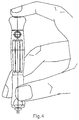
- FIGS. 1 to 3 are first handling of the embodiment shown in FIGS. 1 to 3 shown. With this handling, which enables a quick turning, lie Thumb and middle finger on the concave casing 3, whereas the index finger in the dome-shaped recess 7 of the rotatable cap 5, and so the Presses the screwdriver against the screw.
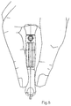
- 5 is an alternative handling shown, which allows turning with higher torque and at the thumb, pointing and Place your middle finger on the concave casing 3, whereas the cap 5 the palm of your hand is supported.
Landscapes
- Engineering & Computer Science (AREA)
- Mechanical Engineering (AREA)
- Manufacturing & Machinery (AREA)
- Details Of Spanners, Wrenches, And Screw Drivers And Accessories (AREA)
- Scissors And Nippers (AREA)
Abstract
Description
- Fig. 1
- eine teilweise geschnittene Seitenansicht eines Ausführungsbeispiels eines erfindungsgemäßen Werkzeughandgriffs und
- Fig. 2
- eine Schnittansicht entlang der Linie II-II gemäß der Darstellung in Fig. 1
- Fig. 3
- eine Schnittansicht entlang der Linie III-III gemäß der Darstellung in Fig. 1,
- Fig. 4
- das in den Fig. 1 bis 3 dargestellte Ausführungsbeispiel in einer ersten Handhabung und
- Fig. 5
- das in den Fig. 1 bis 3 dargestellte Ausführungsbeispiel in einer zweiten Handhabung.
Claims (14)
- Werkzeughandgriff, insbesondere für Elektronik-Schraubendreher, mit einem Grundkörper aus Hartkunststoff, der die Werkzeugklinge trägt und der teilweise von einer Ummantelung aus Weichkunststoff umgeben ist,
dadurch gekennzeichnet,daß der Grundkörper (1) einen handseitigen Abschnitt (2) hat, der eine in axialer Richtung konvexe, ummantelungsfreie Oberfläche aufweist,daß die Ummantelung (3) zwischen dem handseitigen Abschnitt (2) und dem werkzeugseitigen Ende des Werkzeughandgriffs angeordnet ist und eine in axialer Richtung konkave Oberfläche hat, unddaß an dem handseitigen Ende des Grundkörpers (1) eine Kappe (5) drehbar gelagert ist. - Werkzeughandgriff nach Anspruch 1, dadurch gekennzeichnet, daß sich der handseitige Abschnitt (2) über 5 der Längserstreckung des Grundkörpers (1) erstreckt.
- Werkzeughandgriff nach Anspruch 1 oder 2, dadurch gekennzeichnet, daß der Grundkörper (1) rotationssymetrisch ausgebildet ist.
- Werkzeughandgriff nach einem der vorherigen Ansprüche, dadurch gekennzeichnet, daß an dem handseitigen Ende des handseitigen Abschnitts (2) eine sich quer zur Längsachse des Werkzeughandgriffs erstreckende Querbohrung (8) vorgesehen ist.
- Werkzeughandriff nach einem der vorherigen Ansprüche, dadurch gekennzeichnet, daß zwischen dem handseitigen Griffende bzw. der Querbohrung (8) und der Ummantelung (3) an dem Grundkörper sich in axialer Richtung erstrekkende und auf dem Umfang verteilt angeordnete Abflachungen (2a)vorgesehen sind.
- Werkzeughandgriff nach einem der vorherigen Ansprüche, dadurch gekennzeichnet, daß die Ummantelung (3) aus Weichkunststoff in axialer Richtung 2/5 der Längserstreckung des Grundkörpers (1) bedeckt.
- Werkzeughandgriff nach einem der vorherigen Ansprüche, dadurch gekennzeichnet, daß der Grundkörper (1) im Bereich der Ummantelung (3) in axialer Richtung konkav gekrümmt ist.
- Werkzeughandgriff nach einem der vorherigen Ansprüche, dadurch gekennzeichnet, daß der Grundkörper (1) eine Ringnut (9a, 9b) aufweist, in die das Ende der Ummantelung (3) eingreift.
- Handgriff nach einem der vorherigen Ansprüche, dadurch gekennzeichnet, daß die Ummantelung (3) über den größeren Teil ihrer Längserstreckung ein rundes Querschnittsprofil aufweist.
- Werkzeughandgriff nach einem der vorherigen Ansprüche, dadurch gekennzeichnet, daß der Grundkörper (1) das klingenseitige Ende der Ummantelung (3) überragt.
- Werkzeughandgriff nach Anspruch 10, dadurch gekennzeichnet, daß mindestens eine sich über die Oberfläche des klingenseitigen Endes des Grundkörpers (1) und der Ummantelung (3) erstreckenden Abflachung (10) vorgesehen ist, die sich vorzugsweise über 1/5 der Länge der Ummantelung (3) erstreckt.
- Werkzeughandgriff nach einem der vorherigen Ansprüche, dadurch gekennzeichnet, daß der Grundkörper (1) griffseitig von einem Lagerzapfen (4) überragt ist, der mindestens einen, vorzugsweise ringförmig ausgeformte Rastwulst (4a) aufweist, und daß in der Kappe (5) mindestens ein mit dem Rastwulst (4a) zusammenwirkendes Rastelement vorgesehen ist, das zwischen einer Bohrung für den Lagerzapfen und einer kreisförmigen oder einer oder mehrerer kreissegmentförmigen Ausnehmungen angeordnet ist und in Form eines ungeteilten oder geteilten hülsenartiger Steges (5a) ausgebildet ist, wobei der hülsenartige Steg (5a) auf der dem Zapfen zugewandten Seite eine Ringnut aufweist.
- Werkzeughandgriff nach einem der vorherigen Ansprüche, dadurch gekennzeichnet, daß der Grundkörper (1) und/oder die Kappe (5) aus einem Werkstoff hergestellt ist, der gute Lagereigenschaften hat, wie beispielsweise ABS, Polypropylen oder Polyamid.
- Werkzeughandgriff nach einem der vorherigen Ansprüche, dadurch gekennzeichnet, daß der Grundkörper (1) und die Kappe (5) an ihrem Übergangsbereich gleiche Außendurchmesser aufweisen.
Applications Claiming Priority (2)
| Application Number | Priority Date | Filing Date | Title |
|---|---|---|---|
| DE29803967U | 1998-03-07 | ||
| DE29803967U DE29803967U1 (de) | 1998-03-07 | 1998-03-07 | Werkzeug-Griff, insbesondere für Elektronik-Schraubendreher und ähnliche Geräte |
Publications (2)
| Publication Number | Publication Date |
|---|---|
| EP0941814A2 true EP0941814A2 (de) | 1999-09-15 |
| EP0941814A3 EP0941814A3 (de) | 2002-01-23 |
Family
ID=8053693
Family Applications (1)
| Application Number | Title | Priority Date | Filing Date |
|---|---|---|---|
| EP99104545A Withdrawn EP0941814A3 (de) | 1998-03-07 | 1999-03-08 | Werkzeughandgriff |
Country Status (3)
| Country | Link |
|---|---|
| US (1) | US6170123B1 (de) |
| EP (1) | EP0941814A3 (de) |
| DE (1) | DE29803967U1 (de) |
Cited By (1)
| Publication number | Priority date | Publication date | Assignee | Title |
|---|---|---|---|---|
| DE20316813U1 (de) * | 2003-10-31 | 2005-03-10 | Dinkelacker, Wolfgang, Dr.med.dent. | Schraubwerkzeug für Dentalimplantate |
Families Citing this family (24)
| Publication number | Priority date | Publication date | Assignee | Title |
|---|---|---|---|---|
| US5964009A (en) * | 1997-09-15 | 1999-10-12 | Snap-On Technologies, Inc. | Tool with dual-material handle |
| DE19957631B4 (de) * | 1999-11-30 | 2007-01-25 | International Business Machines Corp. | Betätigungsvorrichtung für kleine Tastaturen |
| ITMC20010105A1 (it) * | 2001-11-05 | 2003-05-05 | Piergiacomi Sud Srl | Cacciavite di precisione |
| GB2395154B (en) * | 2002-11-18 | 2006-02-01 | Chih-Ching Hsieh | Screwdriver structure |
| GB2395153B (en) * | 2002-11-18 | 2006-02-22 | Chih-Ching Hsieh | Hand tool handle with rotary cap |
| US7093524B2 (en) * | 2002-11-20 | 2006-08-22 | Chih-Ching Hsieh | Screwdriver structure |
| US20040094001A1 (en) * | 2002-11-20 | 2004-05-20 | Chih-Ching Hsieh | Screwdriver structure |
| US7770262B2 (en) * | 2003-05-19 | 2010-08-10 | Robert Bosch Tool Corporation | Cushion grip handle |
| DE102004012417B4 (de) * | 2003-09-10 | 2010-01-21 | Felo-Werkzeugfabrik Holland-Letz Gmbh | Funktionsteil für einen Schraubendreher und Schraubendrehersatz |
| USD527242S1 (en) * | 2004-10-19 | 2006-08-29 | Chih-Ching Hsieh | Handle |
| USD525853S1 (en) * | 2004-10-19 | 2006-08-01 | Chih-Ching Hsieh | Handle |
| DE102005037504B3 (de) * | 2004-12-23 | 2006-08-24 | Felo-Werkzeugfabrik Holland-Letz Gmbh | Verwendung eines Handgriffes für einen Schraubendreher |
| US20060272126A1 (en) * | 2005-06-01 | 2006-12-07 | Burgess Andrew A | Spinning handle grip assembly for towable luggage item |
| USD553464S1 (en) | 2005-12-02 | 2007-10-23 | Loukas Medical Inc. | Screwdriver handle |
| US20080163463A1 (en) * | 2007-01-10 | 2008-07-10 | Sunex International, Inc. | Tool handle |
| DE102007022291A1 (de) * | 2007-05-12 | 2008-11-13 | Wiha Werkzeuge Gmbh | Handgriff für ein Werkzeug, insbesondere für einen Schraubendreher |
| US7958804B2 (en) * | 2007-12-06 | 2011-06-14 | Custom Spec Engineering, Inc. | Screwdriver handle having removable rotating cap |
| ES2343666B8 (es) * | 2008-10-06 | 2012-02-27 | Micaton Ergonomics, S.L. | Mango para herramientas manuales |
| AU338637S (en) * | 2011-04-14 | 2011-09-26 | Pod Ware Pty Ltd | Leash connector for water sports |
| US8776643B2 (en) | 2012-03-15 | 2014-07-15 | Dentcraft Tools Limited Partnership | Indexable tool |
| US8844099B2 (en) | 2012-10-12 | 2014-09-30 | Sp Industries Holdings, Inc. | Handle device |
| ITMI20140074U1 (it) | 2014-02-26 | 2015-08-26 | Elesa Spa | Impugnatura perfezionata. |
| US10022762B2 (en) | 2014-11-14 | 2018-07-17 | Dentcraft Tools Limited Partnership | Dent repair system |
| CN113787484A (zh) * | 2021-09-28 | 2021-12-14 | 苏州造物空间智能科技有限公司 | 电动螺丝批的操作方法 |
Family Cites Families (15)
| Publication number | Priority date | Publication date | Assignee | Title |
|---|---|---|---|---|
| US2564356A (en) * | 1948-11-12 | 1951-08-14 | Arthur E Dianda | Handle for screw drivers and other hand tools |
| US4093008A (en) * | 1975-10-24 | 1978-06-06 | Lino Martin | Screw driver having capped handle with rotable cap |
| US4290465A (en) * | 1979-10-17 | 1981-09-22 | S/V Tool Company, Inc. | Hand instrument |
| US4417611A (en) * | 1982-02-26 | 1983-11-29 | Kim Jung S | Screwdriver |
| DE3525163A1 (de) * | 1985-07-13 | 1987-01-22 | Werner Hermann Wera Werke | Werkzeugheft, insbesondere fuer schraubendreher |
| USRE34194E (en) * | 1990-03-26 | 1993-03-16 | Oxo International L.P. | Universal handle for hand-held implement |
| FR2675069B1 (fr) * | 1991-04-12 | 1995-07-07 | Facom | Manche d'outil, notamment pour tournevis de precision, et outil correspondant. |
| US5431075A (en) * | 1994-03-31 | 1995-07-11 | Jose A. Cruz | Swivel head screwdriver |
| US5551323A (en) * | 1995-03-22 | 1996-09-03 | Beere Precision Medical Instruments, Inc. | Screwdriver handle |
| USD379750S (en) * | 1996-03-25 | 1997-06-10 | Snap-On Technologies, Inc. | Screwdriver handle |
| DE29619539U1 (de) * | 1996-11-11 | 1996-12-19 | Gebra GmbH & Co Gebr. Raderschad KG, 53773 Hennef | Schraubendreher |
| US5823078A (en) * | 1997-01-15 | 1998-10-20 | Liu; Tsai-Fa | Precision screwdriver equipped with a rotatable cap |
| DE29702884U1 (de) * | 1997-02-19 | 1998-06-18 | Wera-Werk Hermann Werner Gmbh & Co, 42349 Wuppertal | Feinschraubendreher |
| US5964009A (en) * | 1997-09-15 | 1999-10-12 | Snap-On Technologies, Inc. | Tool with dual-material handle |
| USD418034S (en) * | 1998-06-22 | 1999-12-28 | Chiu-Fu Ho | Handle of the screwdriver |
-
1998
- 1998-03-07 DE DE29803967U patent/DE29803967U1/de not_active Expired - Lifetime
-
1999
- 1999-03-03 US US09/261,364 patent/US6170123B1/en not_active Expired - Fee Related
- 1999-03-08 EP EP99104545A patent/EP0941814A3/de not_active Withdrawn
Cited By (1)
| Publication number | Priority date | Publication date | Assignee | Title |
|---|---|---|---|---|
| DE20316813U1 (de) * | 2003-10-31 | 2005-03-10 | Dinkelacker, Wolfgang, Dr.med.dent. | Schraubwerkzeug für Dentalimplantate |
Also Published As
| Publication number | Publication date |
|---|---|
| DE29803967U1 (de) | 1998-04-23 |
| US6170123B1 (en) | 2001-01-09 |
| EP0941814A3 (de) | 2002-01-23 |
Similar Documents
| Publication | Publication Date | Title |
|---|---|---|
| EP0941814A2 (de) | Werkzeughandgriff | |
| DE3525163C2 (de) | ||
| EP0728061B1 (de) | Schere, insbesondere friseurschere | |
| WO1989010244A1 (fr) | Ciseaux, notamment ciseaux de coiffeur | |
| DE29818046U1 (de) | Bürste, insbesondere Zahnbürste | |
| DE2639607A1 (de) | Umstellbares schneidwerkzeug, insbesondere schwenkmesser | |
| EP0515830B1 (de) | Schere | |
| EP0947297B2 (de) | Scherenhälfte für eine Handschere | |
| EP0892700B1 (de) | Schere | |
| DE3042523A1 (de) | Messer mit auswechselbarer klinge | |
| DE10239422A1 (de) | Werkzeug zur spanenden Bearbeitung | |
| DE69503453T2 (de) | Werkzeug zum anziehen von befestigungsmitteln, insbesondere schraubendreher | |
| DE2127641A1 (de) | Operationsschere | |
| DE3023057A1 (de) | Schere | |
| DE19909224B4 (de) | Montagezange mit verstellbarer Maulweite | |
| DE29714823U1 (de) | Werkzeug zum Entfernen von Klebstoffresten o.dgl. von Unterlagen | |
| DE69204883T2 (de) | Werkzeuggriff, insbesondere für Präzisionsschraubendreher, und entsprechende Werkzeuge. | |
| DE29803808U1 (de) | Schraubzwinge | |
| DE20006639U1 (de) | Schere mit Kunststoffgriffen | |
| EP0952902B1 (de) | Drehwerkzeug-system | |
| DE4429126C2 (de) | Schraubendreher | |
| EP0961672B1 (de) | Feinschraubendreher | |
| WO1996041702A1 (de) | Winkelschraubendreher | |
| DE19701406C2 (de) | Drehwerkzeug-System | |
| DE10107071A1 (de) | Griff zur Übertragung von Drehbewegungen im Umfassungsgriff |
Legal Events
| Date | Code | Title | Description |
|---|---|---|---|
| PUAI | Public reference made under article 153(3) epc to a published international application that has entered the european phase |
Free format text: ORIGINAL CODE: 0009012 |
|
| AK | Designated contracting states |
Kind code of ref document: A2 Designated state(s): AT BE CH CY DE DK ES FI FR GB GR IE IT LI LU MC NL PT SE |
|
| AX | Request for extension of the european patent |
Free format text: AL;LT;LV;MK;RO;SI |
|
| PUAL | Search report despatched |
Free format text: ORIGINAL CODE: 0009013 |
|
| AK | Designated contracting states |
Kind code of ref document: A3 Designated state(s): AT BE CH CY DE DK ES FI FR GB GR IE IT LI LU MC NL PT SE |
|
| AX | Request for extension of the european patent |
Free format text: AL;LT;LV;MK;RO;SI |
|
| AKX | Designation fees paid | ||
| REG | Reference to a national code |
Ref country code: DE Ref legal event code: 8566 |
|
| STAA | Information on the status of an ep patent application or granted ep patent |
Free format text: STATUS: THE APPLICATION IS DEEMED TO BE WITHDRAWN |
|
| 18D | Application deemed to be withdrawn |
Effective date: 20020403 |