EP0941431B1 - Druckausgeglichene drehdichtung für turbolader - Google Patents
Druckausgeglichene drehdichtung für turbolader Download PDFInfo
- Publication number
- EP0941431B1 EP0941431B1 EP97950684A EP97950684A EP0941431B1 EP 0941431 B1 EP0941431 B1 EP 0941431B1 EP 97950684 A EP97950684 A EP 97950684A EP 97950684 A EP97950684 A EP 97950684A EP 0941431 B1 EP0941431 B1 EP 0941431B1
- Authority
- EP
- European Patent Office
- Prior art keywords
- seal
- shaft
- passage
- turbine wheel
- turbine
- Prior art date
- Legal status (The legal status is an assumption and is not a legal conclusion. Google has not performed a legal analysis and makes no representation as to the accuracy of the status listed.)
- Expired - Lifetime
Links
Images


Classifications
-
- F—MECHANICAL ENGINEERING; LIGHTING; HEATING; WEAPONS; BLASTING
- F01—MACHINES OR ENGINES IN GENERAL; ENGINE PLANTS IN GENERAL; STEAM ENGINES
- F01D—NON-POSITIVE DISPLACEMENT MACHINES OR ENGINES, e.g. STEAM TURBINES
- F01D25/00—Component parts, details, or accessories, not provided for in, or of interest apart from, other groups
- F01D25/18—Lubricating arrangements
- F01D25/183—Sealing means
- F01D25/186—Sealing means for sliding contact bearing
-
- F—MECHANICAL ENGINEERING; LIGHTING; HEATING; WEAPONS; BLASTING
- F01—MACHINES OR ENGINES IN GENERAL; ENGINE PLANTS IN GENERAL; STEAM ENGINES
- F01D—NON-POSITIVE DISPLACEMENT MACHINES OR ENGINES, e.g. STEAM TURBINES
- F01D25/00—Component parts, details, or accessories, not provided for in, or of interest apart from, other groups
- F01D25/08—Cooling; Heating; Heat-insulation
- F01D25/14—Casings modified therefor
- F01D25/145—Thermally insulated casings
-
- F—MECHANICAL ENGINEERING; LIGHTING; HEATING; WEAPONS; BLASTING
- F04—POSITIVE - DISPLACEMENT MACHINES FOR LIQUIDS; PUMPS FOR LIQUIDS OR ELASTIC FLUIDS
- F04D—NON-POSITIVE-DISPLACEMENT PUMPS
- F04D25/00—Pumping installations or systems
- F04D25/02—Units comprising pumps and their driving means
- F04D25/04—Units comprising pumps and their driving means the pump being fluid-driven
-
- F—MECHANICAL ENGINEERING; LIGHTING; HEATING; WEAPONS; BLASTING
- F04—POSITIVE - DISPLACEMENT MACHINES FOR LIQUIDS; PUMPS FOR LIQUIDS OR ELASTIC FLUIDS
- F04D—NON-POSITIVE-DISPLACEMENT PUMPS
- F04D29/00—Details, component parts, or accessories
- F04D29/08—Sealings
- F04D29/10—Shaft sealings
- F04D29/12—Shaft sealings using sealing-rings
- F04D29/122—Shaft sealings using sealing-rings especially adapted for elastic fluid pumps
- F04D29/124—Shaft sealings using sealing-rings especially adapted for elastic fluid pumps with special means for adducting cooling or sealing fluid
-
- F—MECHANICAL ENGINEERING; LIGHTING; HEATING; WEAPONS; BLASTING
- F16—ENGINEERING ELEMENTS AND UNITS; GENERAL MEASURES FOR PRODUCING AND MAINTAINING EFFECTIVE FUNCTIONING OF MACHINES OR INSTALLATIONS; THERMAL INSULATION IN GENERAL
- F16J—PISTONS; CYLINDERS; SEALINGS
- F16J15/00—Sealings
- F16J15/16—Sealings between relatively-moving surfaces
- F16J15/40—Sealings between relatively-moving surfaces by means of fluid
-
- F—MECHANICAL ENGINEERING; LIGHTING; HEATING; WEAPONS; BLASTING
- F16—ENGINEERING ELEMENTS AND UNITS; GENERAL MEASURES FOR PRODUCING AND MAINTAINING EFFECTIVE FUNCTIONING OF MACHINES OR INSTALLATIONS; THERMAL INSULATION IN GENERAL
- F16J—PISTONS; CYLINDERS; SEALINGS
- F16J15/00—Sealings
- F16J15/44—Free-space packings
- F16J15/441—Free-space packings with floating ring
-
- F—MECHANICAL ENGINEERING; LIGHTING; HEATING; WEAPONS; BLASTING
- F05—INDEXING SCHEMES RELATING TO ENGINES OR PUMPS IN VARIOUS SUBCLASSES OF CLASSES F01-F04
- F05D—INDEXING SCHEME FOR ASPECTS RELATING TO NON-POSITIVE-DISPLACEMENT MACHINES OR ENGINES, GAS-TURBINES OR JET-PROPULSION PLANTS
- F05D2220/00—Application
- F05D2220/40—Application in turbochargers
-
- F—MECHANICAL ENGINEERING; LIGHTING; HEATING; WEAPONS; BLASTING
- F05—INDEXING SCHEMES RELATING TO ENGINES OR PUMPS IN VARIOUS SUBCLASSES OF CLASSES F01-F04
- F05D—INDEXING SCHEME FOR ASPECTS RELATING TO NON-POSITIVE-DISPLACEMENT MACHINES OR ENGINES, GAS-TURBINES OR JET-PROPULSION PLANTS
- F05D2240/00—Components
- F05D2240/40—Use of a multiplicity of similar components
-
- F—MECHANICAL ENGINEERING; LIGHTING; HEATING; WEAPONS; BLASTING
- F16—ENGINEERING ELEMENTS AND UNITS; GENERAL MEASURES FOR PRODUCING AND MAINTAINING EFFECTIVE FUNCTIONING OF MACHINES OR INSTALLATIONS; THERMAL INSULATION IN GENERAL
- F16C—SHAFTS; FLEXIBLE SHAFTS; ELEMENTS OR CRANKSHAFT MECHANISMS; ROTARY BODIES OTHER THAN GEARING ELEMENTS; BEARINGS
- F16C19/00—Bearings with rolling contact, for exclusively rotary movement
- F16C19/02—Bearings with rolling contact, for exclusively rotary movement with bearing balls essentially of the same size in one or more circular rows
- F16C19/14—Bearings with rolling contact, for exclusively rotary movement with bearing balls essentially of the same size in one or more circular rows for both radial and axial load
- F16C19/18—Bearings with rolling contact, for exclusively rotary movement with bearing balls essentially of the same size in one or more circular rows for both radial and axial load with two or more rows of balls
- F16C19/181—Bearings with rolling contact, for exclusively rotary movement with bearing balls essentially of the same size in one or more circular rows for both radial and axial load with two or more rows of balls with angular contact
- F16C19/183—Bearings with rolling contact, for exclusively rotary movement with bearing balls essentially of the same size in one or more circular rows for both radial and axial load with two or more rows of balls with angular contact with two rows at opposite angles
- F16C19/184—Bearings with rolling contact, for exclusively rotary movement with bearing balls essentially of the same size in one or more circular rows for both radial and axial load with two or more rows of balls with angular contact with two rows at opposite angles in O-arrangement
-
- F—MECHANICAL ENGINEERING; LIGHTING; HEATING; WEAPONS; BLASTING
- F16—ENGINEERING ELEMENTS AND UNITS; GENERAL MEASURES FOR PRODUCING AND MAINTAINING EFFECTIVE FUNCTIONING OF MACHINES OR INSTALLATIONS; THERMAL INSULATION IN GENERAL
- F16C—SHAFTS; FLEXIBLE SHAFTS; ELEMENTS OR CRANKSHAFT MECHANISMS; ROTARY BODIES OTHER THAN GEARING ELEMENTS; BEARINGS
- F16C2360/00—Engines or pumps
- F16C2360/23—Gas turbine engines
- F16C2360/24—Turbochargers
-
- F—MECHANICAL ENGINEERING; LIGHTING; HEATING; WEAPONS; BLASTING
- F16—ENGINEERING ELEMENTS AND UNITS; GENERAL MEASURES FOR PRODUCING AND MAINTAINING EFFECTIVE FUNCTIONING OF MACHINES OR INSTALLATIONS; THERMAL INSULATION IN GENERAL
- F16C—SHAFTS; FLEXIBLE SHAFTS; ELEMENTS OR CRANKSHAFT MECHANISMS; ROTARY BODIES OTHER THAN GEARING ELEMENTS; BEARINGS
- F16C27/00—Elastic or yielding bearings or bearing supports, for exclusively rotary movement
- F16C27/04—Ball or roller bearings, e.g. with resilient rolling bodies
- F16C27/045—Ball or roller bearings, e.g. with resilient rolling bodies with a fluid film, e.g. squeeze film damping
-
- F—MECHANICAL ENGINEERING; LIGHTING; HEATING; WEAPONS; BLASTING
- F16—ENGINEERING ELEMENTS AND UNITS; GENERAL MEASURES FOR PRODUCING AND MAINTAINING EFFECTIVE FUNCTIONING OF MACHINES OR INSTALLATIONS; THERMAL INSULATION IN GENERAL
- F16C—SHAFTS; FLEXIBLE SHAFTS; ELEMENTS OR CRANKSHAFT MECHANISMS; ROTARY BODIES OTHER THAN GEARING ELEMENTS; BEARINGS
- F16C33/00—Parts of bearings; Special methods for making bearings or parts thereof
- F16C33/72—Sealings
- F16C33/76—Sealings of ball or roller bearings
Definitions
- This invention relates generally to turbocharger shaft seal arrangements. More particularly, a pressure balanced dual piston ring configuration on the shaft in combination with a compression seal engaged between the center housing and turbine wheel shroud provides an effective turbine end seal for avoiding contamination by condensates and vapor in the exhaust gas driving the turbine.
- Turbochargers are being employed in numerous applications including conventional internal combustion engine charge air boosting and new concepts for turbopumping of exhaust gases and pressurizing reactants for power generation systems such as fuel cells
- operational requirements dictate the need for relatively leak-free seals between the shaft bearings within the center housing, and the rotating turbine and compressor wheels. This is particularly true at the turbine end of the shaft, since the turbine typically operates in a relatively high temperature environment.
- the prior art typically employs one or more sealing rings on the turbine shaft in a labyrinth arrangement for preventing leakage on one or both the turbine and compressor sides of the shaft. Additionally, venting the compressor end seal within the center housing to allow lubricant contacting the seal to drain and slinger arrangements on the shaft for pumping excess lubricant radially away from the seal rings are employed for increasing efficiency of the overall seal configuration.
- the present invention provides increased sealing effectiveness over the prior art by combining plural sealing elements with an integral pressure balancing cavity receiving pressurizing gas from the compressed gas stream or an external source.
- EP 357 246 describes a shaft seal for a turbocharger with first and second spaced seal rings between the compressor and bearings for the shaft. Oil leakage from the bearing side to the compressor side is prevented by keeping the difference between the pressure inbetween the seal rings and that on the bearing side less than that at which oil leak occurs.
- the present invention provides A seal system for a turbine wheel shaft employed in a turbocharger comprising: a shaft (22) supporting a turbine wheel (28) and a compressor wheel (24), said shaft (22) rotatably retained within a shaft bore (26) extending through a centre housing (105) and a turbine wheel shroud (34); first and second seal rings (66, 68) mounted on the shaft (22) characterised by the seal rings being proximate the turbine wheel (28), the first ring (66) sealingly engaging a circumferential surface of the shaft bore (26) in the centre housing (10) and the second ring (68) sealingly engaging a circumferential surface of the shaft bore (26) in the turbine wheel shroud (34); a passage (74) for introducing a pressurizing gas, the passage communicating with the shaft bore (26) intermediate the first and second seal rings (66, 68); means for supplying pressurizing gas to the passage; and a compression seal (82) engaged between the centre housing (10) and turbine wheel shroud (34) outboard of the passage (74).
- a positive face seal on the compressor end of the shaft in combination with the pressure balanced twin seal ring and compression seal arrangement of the turbine end provides efficacious seals for preventing contamination of the compression gas stream and avoiding contamination of the lubricant respectively.
- the O-ring seal is replaced with an appropriate high temperature compression seal.
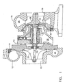
- FIG. 1 shows a turbocharger embodiment employing the present invention which includes a center housing 10, a compressor housing 12 connected to the center housing by bolts (not shown) received in thread holes 14 or other conventional means, and a turbine housing 16 connected to the center housing (not shown) received in threaded holes 18.
- a bearing assembly, generally designated 20, is carried within the center housing and a shaft 22 is engaged by a center bore of the bearing.
- a compressor wheel 24 is mounted on one end of the shaft which extends through a first bore 26 in the compressor end of the center housing concentric with the center bore.
- a turbine wheel 28 is mounted on the second end of the shaft which extends through a second bore 30, also concentric with the center bore, in the turbine end of the center housing and a third bore 32, also concentric with the center bore, in a turbine wheel shroud 34.
- the turbine wheel shroud (defined in alternative embodiments as a turbine backface or heat shield) is mounted to the center housing or constrained between the center housing and turbine housing for the embodiment shown in the drawings.
- the first, second and third bores and the center bore of the bearing collectively comprise a shaft bore for the turbocharger.
- the turbocharger operates conventionally with expansion gas provided through a volute 36 in the turbine housing to aerodynamically drive the turbine, exhausting through outlet 38 in the turbine housing. Rotation of the turbine is carried through the shaft to rotate the compressor wheel, drawing compression gas through the inlet 40 in the compressor housing with compressed gas exiting the compressor into volute 42 for communication to an engine inlet manifold or other compressed gas user.
- the bearing system includes a bearing outer ring 44 received within a bearing carrier 46.
- a bearing inner ring 48 which is mounted for rotation with the shaft, is supported by axially separated sets of roller bearing elements 50 and 52.
- Lubricating oil injection channels, generally designated 54 and a collection sump 56 constitute the lubrication system for the bearings and shaft.
- Compressive loads are carried by a collar 58 on the turbine end of the shaft and collar 60 and ring 62 on the compressor end of the shat.
- thrust loads are carried by the roller bearing elements.
- journal bearings and associated thrust bearings are employed as the bearing system for the shaft. Contouring of the turbine end of the shaft, generally designated 64 provides a slinger effect for oil collection.
- First and second seal rings 66 and 68 mounted on the shaft provide a multielement seal with the first ring sealingly engaging a circumferential surface 70 of the second bore 30 in the center housing, and the second ring sealingly engaging a circumferential surface 72 of the third bore 32 in the turbine wheel shroud.
- An O-ring seal 82 engaged between the center housing and turbine wheel shroud outboard of the channel completes the seal on the turbine end of the shaft.
- Pressurizing gas is provided to passage 74 through port 84, as shown in FIG. 3, which is connected to an external source such as compressed brake air tank in a vehicle application, independent pressurized gas tanks or fed from the compressor volute of the turbocharger, or further downstream in the gas supply system.
- an external source such as compressed brake air tank in a vehicle application, independent pressurized gas tanks or fed from the compressor volute of the turbocharger, or further downstream in the gas supply system.
- the first portion 76 of passage 74 is integrally cast in the center housing for the embodiment shown in the drawings, and extends to the turbine end face of the center housing.
- the circumferential channel 78 carries the pressurizing gas for equal distribution around the shaft between the seal rings through the clearance gap between the end face and turbine wheel shroud.
- the pressurizing gas at a higher absolute pressure than the expansion gas in the turbine provides a pressure gradient across the outer seal ring precluding transmission of contaminants such as water vapor, corrosive condensates or other potential contaminants from the expansion gas to the lubricating system for the turbocharger.
- the pressure established between the seals provides a gradient across the inner seal ring assisting the labyrinth configuration of the structure of the seal in precluding leakage of lubricating oil into the turbine housing.
- a positive face seal 86 is provided on the compressor end of the shaft, which in combination with the pressure balanced twin seal ring and compression seal arrangement of the turbine end provides an efficacious seal for preventing contamination of the compression gas stream
- An exemplary seal for use on the compressor end of the shaft is a carbon face seal such as that disclosed in U.S Patent 4,420,160 entitled “Face Seal System” issued December 13,1983 to Herman C. Laham and having a common assignee with the present application.
- the O-ring seal is replaced with an appropriate high temperature compression seal such as a compressible metal ring.
Landscapes
- Engineering & Computer Science (AREA)
- General Engineering & Computer Science (AREA)
- Mechanical Engineering (AREA)
- Supercharger (AREA)
- Sealing Using Fluids, Sealing Without Contact, And Removal Of Oil (AREA)
Claims (9)
- Dichtungssystem für eine Turbinenradwelle in einem Turbolader, das Folgendendes aufweist:eine Welle (22), die ein Turbinenrad (28) und ein Verdichterrad (24) trägt, wobei die Welle (22) drehbar in einer Wellenbohrung (26) gehalten wird, die sich durch ein Zentralgehäuse (105) und eine Turbinenradhaube (34) erstreckt;einen ersten und einen zweiten Dichtungsring (66, 68), die auf der Welle (22) montiert sind, dadurch gekennzeichnet, dass die Dichtungsringe neben dem Turbinenrad (28) angeordnet sind, wobei der erste Ring (66) abdichtend in eine Umfangsfläche der Wellenbohrung (26) im Zentralgehäuse (10) und der zweite Ring (68) abdichtend in eine Umfangsfläche der Wellenbohrung (26) in der Turbinenradhaube (34) eingreift;ein Durchlass (74) zur Zuführung von mit Druck beaufschlagtem Gas, der mit der Wellenbohrung (26) zwischen dem ersten und dem zweiten Dichtungsring (66, 68) in Verbindung steht;Mittel zur Beschickung des Durchlasses mit mit Druck beaufschlagtem Gas; undeine Anschlagdichtung (82), die zwischen dem zentralgehäuse (10) und der Turbinenradhaube (34) außerhalb des Durchlasses (74) eingreift.
- Dichtungssystem nach Anspruch 1, dadurch gekennzeichnet, dass der Durchlass (74) einen ersten Abschnitt (76) als Bestandteil des Zentralgehäuses (10) und einen zweiten Abschnitt mit einem Umfangskanal (78) an der Innenseite der Turbinenradhaube (34) aufweist.
- Dichtungssystem nach Anspruch 1, dadurch gekennzeichnet, dass die Anschlagdichtung einen O-Ring (82) aufweist.
- Dichtungssystem nach Anspruch 1, dadurch gekennzeichnet, dass die Anschlagdichtung einen verformbaren Metallring aufweist.
- Dichtungssystem nach Anspruch 2, dadurch gekennzeichnet, dass das Zentralgehäuse (10) ein Gussstück ist und dass der erste Abschnitt (76) des Durchlasses (74) als Bestandteil des Zentralgehäuses (10) gegossen wird.
- Dichtungssystem nach Anspruch 2, dadurch gekennzeichnet, dass das Mittel zur Beschickung mit mit Druck beaufschlagtem Gas eine Öffnung im Zentralgehäuse (10) aufweist, die funktionsfähig mit dem ersten Abschnitt (76) des Durchlasses (74) und einer Druckgasquelle verbunden ist.
- Dichtungssystem nach Anspruch 6, dadurch gekennzeichnet, dass die Druckgasquelle eine Druckentnahmestelle an einem Diffusor (36) aufweist, der verdichtetes Gas vom Verdichterrad (24) erhält.
- System nach Anspruch 6, dadurch gekennzeichnet, dass die Druckgasquelle einen Kompressionsgasspeicher aufweist.
- Dichtungssystem nach einem der Ansprüche 1 bis 8, das außerdem eine formschlüssige Gleitringdichtung aufweist, die funktionsfähig in die Welle neben dem Verdichterrad eingreift.
Applications Claiming Priority (3)
| Application Number | Priority Date | Filing Date | Title |
|---|---|---|---|
| US08/774,327 US5890881A (en) | 1996-11-27 | 1996-11-27 | Pressure balanced turbocharger rotating seal |
| US774327 | 1996-11-27 | ||
| PCT/US1997/021575 WO1998023886A1 (en) | 1996-11-27 | 1997-11-25 | Pressure balanced turbocharger rotating seal |
Publications (2)
| Publication Number | Publication Date |
|---|---|
| EP0941431A1 EP0941431A1 (de) | 1999-09-15 |
| EP0941431B1 true EP0941431B1 (de) | 2003-04-16 |
Family
ID=25100913
Family Applications (1)
| Application Number | Title | Priority Date | Filing Date |
|---|---|---|---|
| EP97950684A Expired - Lifetime EP0941431B1 (de) | 1996-11-27 | 1997-11-25 | Druckausgeglichene drehdichtung für turbolader |
Country Status (10)
| Country | Link |
|---|---|
| US (1) | US5890881A (de) |
| EP (1) | EP0941431B1 (de) |
| JP (1) | JP2001506735A (de) |
| KR (1) | KR20000057256A (de) |
| CN (1) | CN1092768C (de) |
| AU (1) | AU5362298A (de) |
| BR (1) | BR9714473A (de) |
| CA (1) | CA2272368A1 (de) |
| DE (1) | DE69721036T2 (de) |
| WO (1) | WO1998023886A1 (de) |
Cited By (1)
| Publication number | Priority date | Publication date | Assignee | Title |
|---|---|---|---|---|
| DE112008002729B4 (de) | 2007-10-13 | 2023-01-19 | Cummins Turbo Technologies Ltd. | Turbomaschine |
Families Citing this family (70)
| Publication number | Priority date | Publication date | Assignee | Title |
|---|---|---|---|---|
| US6220829B1 (en) * | 1998-10-05 | 2001-04-24 | Glenn F. Thompson | Turbocharger rotor with low-cost ball bearing |
| US6338614B1 (en) * | 2000-10-06 | 2002-01-15 | Honeywell International Inc. | Turbocharger annular seal gland |
| US6682222B2 (en) * | 2001-08-22 | 2004-01-27 | General Electric Company | Bi-directional oil scoop for bearing lubrication |
| JP2003065289A (ja) | 2001-08-24 | 2003-03-05 | Nsk Ltd | ウォータポンプ用シール装置とウォータポンプ用回転支持装置とウォータポンプ |
| JP2003074491A (ja) | 2001-09-04 | 2003-03-12 | Nsk Ltd | ウォータポンプ用シール装置とウォータポンプ用回転支持装置とウォータポンプ |
| US6984465B2 (en) * | 2002-09-05 | 2006-01-10 | Donaldson Company, Inc | Seal-leak detector arrangement for compressors and other equipment |
| EP1585888B1 (de) * | 2003-01-10 | 2018-09-26 | Honeywell International Inc. | Turbolader |
| DE50307710D1 (de) * | 2003-08-15 | 2007-08-30 | Abb Turbo Systems Ag | Rotationsdichtung |
| US7108488B2 (en) * | 2004-03-26 | 2006-09-19 | Honeywell International, Inc. | Turbocharger with hydrodynamic foil bearings |
| US7214037B2 (en) * | 2004-06-28 | 2007-05-08 | Honeywell International, Inc. | Retention of ball bearing cartridge for turbomachinery |
| US7104693B2 (en) * | 2004-06-28 | 2006-09-12 | Honeywell International, Inc. | Multi-thickness film layer bearing cartridge and housing |
| WO2006005355A1 (en) * | 2004-07-09 | 2006-01-19 | Honeywell International Inc. | Turbocharger housing, turbocharger and a multiturbocharger system |
| JP2006200651A (ja) * | 2005-01-21 | 2006-08-03 | Jtekt Corp | 過給機用転がり軸受装置 |
| US7753591B2 (en) * | 2005-06-30 | 2010-07-13 | Honeywell International Inc. | Turbocharger bearing and associated components |
| US20070059188A1 (en) * | 2005-09-09 | 2007-03-15 | Borgwarner Inc. | Aerodynamically enhanced bearing housing pocket geometry |
| US20070092387A1 (en) * | 2005-10-21 | 2007-04-26 | Borgwarner Inc. | Oil discharge assembly for a turbocharger |
| DE502005004418D1 (de) * | 2005-10-24 | 2008-07-24 | Borgwarner Inc | Turbolader |
| US20070110351A1 (en) * | 2005-11-16 | 2007-05-17 | Honeywell International, Inc. | Centering mechanisms for turbocharger bearings |
| KR101304390B1 (ko) * | 2006-11-01 | 2013-09-05 | 보르그워너 인코퍼레이티드 | 터빈 열 차폐부 어셈블리 |
| US20080267548A1 (en) * | 2007-02-05 | 2008-10-30 | Schaeffler Kg | Bearing arrangement for the shaft of a turbo-charger |
| DE102007027869B4 (de) * | 2007-06-18 | 2010-04-29 | Continental Automotive Gmbh | Turbolader mit einem Turboladergehäuse |
| US8365406B2 (en) | 2007-11-28 | 2013-02-05 | Honeywell International Inc. | Bearing and shaft wheel assembly balancing techniques and equipment for turbochargers |
| US20090136368A1 (en) * | 2007-11-28 | 2009-05-28 | Steven Don Arnold | Center Housing and Bearing and Shaft Wheel Assembly for Turbochargers |
| JP2009167803A (ja) * | 2008-01-10 | 2009-07-30 | Jtekt Corp | 過給機 |
| US8092162B2 (en) * | 2008-03-06 | 2012-01-10 | Honeywell International Inc. | Turbocharger assembly having heat shield-centering arrangements |
| GB0814764D0 (en) | 2008-08-13 | 2008-09-17 | Cummins Turbo Tech Ltd | Engine braking method and system |
| US8602655B2 (en) * | 2009-03-27 | 2013-12-10 | Toyota Jidosha Kabushiki Kaisha | Bearing unit for turbocharger |
| DE112010001693T5 (de) | 2009-04-20 | 2013-01-03 | Borgwarner Inc. | Isolierender abstandshalter für kugellagereinsatz |
| US8545172B2 (en) * | 2009-06-15 | 2013-10-01 | Honeywell International, Inc. | Turbocharger having nozzle ring locating pin and an integrated locator and heat shield |
| US8496452B2 (en) | 2009-08-26 | 2013-07-30 | Honeywell International Inc. | Bearing spacer and housing |
| US8961128B2 (en) * | 2009-08-26 | 2015-02-24 | Honeywell International Inc. | Bearing spacer and housing |
| US20110236193A1 (en) * | 2010-03-25 | 2011-09-29 | Schaeffler Technologies Gmbh & Co. Kg | Turbocharger bearing lubrication |
| DE102010003796A1 (de) * | 2010-04-09 | 2011-10-13 | Abb Turbo Systems Ag | Wellenabdichtung |
| US8449199B2 (en) * | 2010-10-27 | 2013-05-28 | Precision Turbo & Engine Rebuilders, Inc. | Bearing retention assembly for and method of assembling turbochargers |
| DE102010054939A1 (de) * | 2010-12-17 | 2012-06-21 | Schaeffler Technologies Gmbh & Co. Kg | Lageranordnung für einen Turbolader und Turbolader |
| US9046036B2 (en) * | 2011-05-31 | 2015-06-02 | Honeywell International Inc. | Bearing assembly |
| US8915708B2 (en) * | 2011-06-24 | 2014-12-23 | Caterpillar Inc. | Turbocharger with air buffer seal |
| CN102359597A (zh) * | 2011-09-04 | 2012-02-22 | 陈发谦 | 增压器压气端封油装置 |
| US8911202B2 (en) * | 2011-09-20 | 2014-12-16 | Honeywell International Inc. | Turbocharger rotating assembly |
| KR101989548B1 (ko) * | 2012-03-30 | 2019-06-14 | 보르그워너 인코퍼레이티드 | 일체형 열 실드를 구비한 터보차저 베어링 하우징 |
| DE102012206556B4 (de) * | 2012-04-20 | 2015-10-29 | Schaeffler Technologies AG & Co. KG | Lagereinheit für einen Turbolader |
| US9163641B2 (en) * | 2012-06-21 | 2015-10-20 | Electro-Motive Diesel, Inc. | Turbocharger support housing having improved drainage |
| DE112013002332T5 (de) * | 2012-06-25 | 2015-01-22 | Borgwarner Inc. | Abgasturbolader |
| US20150330240A1 (en) * | 2012-12-17 | 2015-11-19 | Borgwarner Inc. | Turbocharger outboard purge seal |
| CN103742418B (zh) * | 2013-01-08 | 2016-10-05 | 摩尔动力(北京)技术股份有限公司 | 纯净工质叶轮机构 |
| DE102015106638A1 (de) * | 2014-07-02 | 2016-01-07 | Pierburg Gmbh | Befestigungsvorrichtung sowie Verfahren zur Befestigung eines Laufrades eines Verdichters auf einer Antriebswelle |
| US9212700B1 (en) * | 2014-12-17 | 2015-12-15 | Borgwarner Inc. | High efficiency and durable ball bearing system with reduced turbine end heat transfer |
| US11078962B2 (en) | 2014-12-23 | 2021-08-03 | Cummins Ltd. | Bearing assembly support |
| US9638198B2 (en) * | 2015-02-24 | 2017-05-02 | Borgwarner Inc. | Shaftless turbocharger |
| US20160281647A1 (en) * | 2015-03-09 | 2016-09-29 | Caterpillar Inc. | Turbocharger and Method |
| US9822700B2 (en) * | 2015-03-09 | 2017-11-21 | Caterpillar Inc. | Turbocharger with oil containment arrangement |
| US9915172B2 (en) * | 2015-03-09 | 2018-03-13 | Caterpillar Inc. | Turbocharger with bearing piloted compressor wheel |
| US9752536B2 (en) * | 2015-03-09 | 2017-09-05 | Caterpillar Inc. | Turbocharger and method |
| US9739238B2 (en) * | 2015-03-09 | 2017-08-22 | Caterpillar Inc. | Turbocharger and method |
| US9683520B2 (en) * | 2015-03-09 | 2017-06-20 | Caterpillar Inc. | Turbocharger and method |
| US9638138B2 (en) * | 2015-03-09 | 2017-05-02 | Caterpillar Inc. | Turbocharger and method |
| JP6380767B2 (ja) * | 2015-12-14 | 2018-08-29 | ドゥサン ヘヴィー インダストリーズ アンド コンストラクション カンパニー リミテッド | ベアリングオイル除去型ロータ構造 |
| US10316742B2 (en) * | 2016-05-13 | 2019-06-11 | Garrett Transportation I Inc. | Turbocharger assembly |
| US10077712B2 (en) * | 2016-07-01 | 2018-09-18 | Borgwarner Inc. | Venting system for a bearing housing thermal dam of a turbocharger |
| CN106441908B (zh) * | 2016-10-26 | 2018-10-30 | 福州大学 | 应用于涡轮增压器性能试验台上基于增压器转速的气封装置及使用方法 |
| CN108223113B (zh) * | 2017-11-09 | 2021-07-13 | 江苏索特动力工程有限公司 | 电控阀涡轮增压器 |
| CN108252961A (zh) * | 2017-12-28 | 2018-07-06 | 中国航发四川燃气涡轮研究院 | 一种用于轴流压气机性能试验的轴向力平衡装置 |
| JP2020007989A (ja) * | 2018-07-11 | 2020-01-16 | トヨタ自動車株式会社 | 圧縮装置 |
| US11384772B2 (en) * | 2018-09-19 | 2022-07-12 | Borgwarner Inc. | Rotating machine and mating ring included therein |
| US11920605B2 (en) | 2018-09-19 | 2024-03-05 | Borgwarner Inc. | Rotating machine and mating ring included therein |
| US10746099B1 (en) * | 2019-04-03 | 2020-08-18 | GM Global Technology Operations LLC | Multi-step bore turbocharger |
| CN110518736B (zh) * | 2019-08-18 | 2022-03-15 | 中车永济电机有限公司 | 一种牵引电机油润滑密封结构 |
| US11624375B2 (en) * | 2021-01-13 | 2023-04-11 | Garrett Transportation I Inc | Moisture removal system for electric compressor device |
| US20220251970A1 (en) * | 2021-02-10 | 2022-08-11 | GM Global Technology Operations LLC | Turbocharger with anti-coking coating |
| DE102021124357A1 (de) * | 2021-09-21 | 2023-03-23 | MTU Aero Engines AG | Hitzeschutzelement für eine Lagerkammer einer Gasturbine |
Family Cites Families (25)
| Publication number | Priority date | Publication date | Assignee | Title |
|---|---|---|---|---|
| GB757591A (en) * | 1953-04-07 | 1956-09-19 | British Leyland Motor Corp | Turbine-driven supercharger |
| US2918207A (en) * | 1957-12-16 | 1959-12-22 | Gen Motors Corp | Turbocharger |
| US3090546A (en) * | 1960-12-29 | 1963-05-21 | Schwitzer Corp | Pressurized oil seal for rotating machinery |
| US3310230A (en) * | 1965-09-22 | 1967-03-21 | Chicago Pneumatic Tool Co | Hydraulic gas seal system for pistontype gas compressor |
| US3411706A (en) * | 1966-08-24 | 1968-11-19 | Wallace Murray Corp | Bearing durability enhancement device for turbocharger |
| US3565497A (en) * | 1969-05-23 | 1971-02-23 | Caterpillar Tractor Co | Turbocharger seal assembly |
| US3693985A (en) * | 1971-05-12 | 1972-09-26 | Arthur M Dillner | End face fluid seal unit |
| DE2257188C3 (de) * | 1972-11-22 | 1975-04-17 | Karl Dipl.-Ing. 7024 Bernhausen Schlecht | Dichtungsanordnung, insbesondere für Betonmischkessel |
| DE2437530A1 (de) * | 1974-08-03 | 1976-02-12 | Kuehnle Kopp Kausch Ag | Abgasturbolader |
| US4196910A (en) * | 1977-05-19 | 1980-04-08 | Ishikawajima-Harima Jukogyo Kabushiki Kaisha | Shaft sealing device for turbocharger |
| US4157834A (en) * | 1978-03-20 | 1979-06-12 | The Garrett Corporation | Seal system |
| DE2911682A1 (de) * | 1979-03-24 | 1980-10-02 | Daimler Benz Ag | Abgasturbolader an einer brennkraftmaschine |
| US4268229A (en) * | 1979-04-19 | 1981-05-19 | The Garrett Corporation | Turbocharger shaft seal arrangement |
| JPS5613513U (de) * | 1979-07-10 | 1981-02-05 | ||
| US4420160A (en) * | 1980-03-10 | 1983-12-13 | The Garrett Corporation | Face seal system |
| CA1148188A (en) * | 1980-03-10 | 1983-06-14 | Herman C. Laham | Face seal system |
| US4377290A (en) * | 1982-03-22 | 1983-03-22 | John Crane-Houdaille, Inc. | Symmetrical seal package for multiple face seals |
| US4613288A (en) * | 1983-05-26 | 1986-09-23 | The Garrett Corporation | Turbocharger |
| US4725206A (en) * | 1984-12-20 | 1988-02-16 | The Garrett Corporation | Thermal isolation system for turbochargers and like machines |
| DE3737932A1 (de) * | 1987-11-07 | 1989-05-18 | Mtu Friedrichshafen Gmbh | Dichtungsvorrichtung zwischen welle und gehaeuse einer stroemungsmaschine |
| US5076765A (en) * | 1988-08-03 | 1991-12-31 | Nissan Motor Company, Altd. | Shaft seal arrangement of turbocharger |
| DE3843429A1 (de) * | 1988-12-23 | 1990-06-28 | Klein Schanzlin & Becker Ag | Wellenabdichtung an stroemungsmaschinen |
| US4986733A (en) * | 1989-10-30 | 1991-01-22 | Allied-Signal, Inc. | Turbocharger compressor wheel assembly with boreless hub compressor wheel |
| US5145334A (en) * | 1989-12-12 | 1992-09-08 | Allied-Signal Inc. | Turbocharger bearing retention and lubrication system |
| US5176497A (en) * | 1991-01-22 | 1993-01-05 | Allied-Signal Inc. | Boreless hub compressor wheel assembly for a turbocharger |
-
1996
- 1996-11-27 US US08/774,327 patent/US5890881A/en not_active Expired - Lifetime
-
1997
- 1997-11-25 JP JP52481598A patent/JP2001506735A/ja not_active Ceased
- 1997-11-25 KR KR1019990704644A patent/KR20000057256A/ko not_active Application Discontinuation
- 1997-11-25 CN CN97181540A patent/CN1092768C/zh not_active Expired - Lifetime
- 1997-11-25 EP EP97950684A patent/EP0941431B1/de not_active Expired - Lifetime
- 1997-11-25 AU AU53622/98A patent/AU5362298A/en not_active Abandoned
- 1997-11-25 WO PCT/US1997/021575 patent/WO1998023886A1/en active IP Right Grant
- 1997-11-25 CA CA002272368A patent/CA2272368A1/en not_active Abandoned
- 1997-11-25 DE DE69721036T patent/DE69721036T2/de not_active Expired - Lifetime
- 1997-11-25 BR BR9714473-8A patent/BR9714473A/pt not_active IP Right Cessation
Cited By (1)
| Publication number | Priority date | Publication date | Assignee | Title |
|---|---|---|---|---|
| DE112008002729B4 (de) | 2007-10-13 | 2023-01-19 | Cummins Turbo Technologies Ltd. | Turbomaschine |
Also Published As
| Publication number | Publication date |
|---|---|
| US5890881A (en) | 1999-04-06 |
| CA2272368A1 (en) | 1998-06-04 |
| BR9714473A (pt) | 2000-05-16 |
| AU5362298A (en) | 1998-06-22 |
| EP0941431A1 (de) | 1999-09-15 |
| CN1245553A (zh) | 2000-02-23 |
| DE69721036T2 (de) | 2004-02-12 |
| WO1998023886A1 (en) | 1998-06-04 |
| CN1092768C (zh) | 2002-10-16 |
| JP2001506735A (ja) | 2001-05-22 |
| DE69721036D1 (de) | 2003-05-22 |
| KR20000057256A (ko) | 2000-09-15 |
Similar Documents
| Publication | Publication Date | Title |
|---|---|---|
| EP0941431B1 (de) | Druckausgeglichene drehdichtung für turbolader | |
| EP1387061B1 (de) | Ölabdichtung eines Turboladers | |
| US6368077B1 (en) | Turbocharger shaft dual phase seal | |
| EP2495415B1 (de) | Motorbremssystem | |
| US7108488B2 (en) | Turbocharger with hydrodynamic foil bearings | |
| US8147181B2 (en) | Device for inhibiting the flow of oil along a rotating shaft | |
| US6418722B1 (en) | Turbocharger bearing system | |
| US20130094938A1 (en) | Turbomachine | |
| WO2008149075A1 (en) | Sealing method for a turbocharger shaft seal and corresponding turbocharger | |
| US4376617A (en) | Turbocharger for use in an internal combustion engine | |
| CN103206271B (zh) | 涡轮机轴密封装置 | |
| US6966746B2 (en) | Bearing pressure balance apparatus | |
| US11359645B2 (en) | Compressor with cooled air passage and liquid coolant passage in axial heat exchanger arrangement | |
| US5066192A (en) | Oil sealing system for a turbo charger | |
| CZ288110B6 (cs) | Prstencové ložiskové pouzdro | |
| CN102016237A (zh) | 带有密封空气通道的引导装置的支撑环 | |
| US12037949B2 (en) | Bearing-supported shaft assembly | |
| US20220106893A1 (en) | Shaft Seal System, Turbomachine with Shaft Seal System, and Method of Sealing a Shaft | |
| WO2023135174A1 (en) | Sealing device, turbomachine and method of sealing a bearing cover from a bearing housing | |
| CN215170344U (zh) | 一种涡轮增压器结构及其中间壳 | |
| RU2750220C1 (ru) | Турбокомпрессор для наддува двигателя внутреннего сгорания | |
| WO2024179880A1 (en) | Shaft bearing assembly for a shaft of a turbomachine and turbomachine | |
| JPS63106326A (ja) | 排気タ−ビンのシ−ル装置 | |
| CN111322122A (zh) | 一种透平轴径向嵌齿密封 | |
| JP2002349208A (ja) | タービン高圧車室 |
Legal Events
| Date | Code | Title | Description |
|---|---|---|---|
| PUAI | Public reference made under article 153(3) epc to a published international application that has entered the european phase |
Free format text: ORIGINAL CODE: 0009012 |
|
| 17P | Request for examination filed |
Effective date: 19990604 |
|
| AK | Designated contracting states |
Kind code of ref document: A1 Designated state(s): DE FR GB IT SE |
|
| 17Q | First examination report despatched |
Effective date: 20010427 |
|
| GRAH | Despatch of communication of intention to grant a patent |
Free format text: ORIGINAL CODE: EPIDOS IGRA |
|
| GRAH | Despatch of communication of intention to grant a patent |
Free format text: ORIGINAL CODE: EPIDOS IGRA |
|
| RAP1 | Party data changed (applicant data changed or rights of an application transferred) |
Owner name: HONEYWELL INTERNATIONAL INC. |
|
| GRAA | (expected) grant |
Free format text: ORIGINAL CODE: 0009210 |
|
| AK | Designated contracting states |
Designated state(s): DE FR GB IT SE |
|
| REG | Reference to a national code |
Ref country code: GB Ref legal event code: FG4D |
|
| REF | Corresponds to: |
Ref document number: 69721036 Country of ref document: DE Date of ref document: 20030522 Kind code of ref document: P |
|
| REG | Reference to a national code |
Ref country code: SE Ref legal event code: TRGR |
|
| ET | Fr: translation filed | ||
| PLBE | No opposition filed within time limit |
Free format text: ORIGINAL CODE: 0009261 |
|
| STAA | Information on the status of an ep patent application or granted ep patent |
Free format text: STATUS: NO OPPOSITION FILED WITHIN TIME LIMIT |
|
| 26N | No opposition filed |
Effective date: 20040119 |
|
| REG | Reference to a national code |
Ref country code: FR Ref legal event code: PLFP Year of fee payment: 19 |
|
| REG | Reference to a national code |
Ref country code: FR Ref legal event code: PLFP Year of fee payment: 20 |
|
| PGFP | Annual fee paid to national office [announced via postgrant information from national office to epo] |
Ref country code: DE Payment date: 20161130 Year of fee payment: 20 Ref country code: FR Payment date: 20161017 Year of fee payment: 20 Ref country code: GB Payment date: 20161026 Year of fee payment: 20 |
|
| PGFP | Annual fee paid to national office [announced via postgrant information from national office to epo] |
Ref country code: IT Payment date: 20161114 Year of fee payment: 20 Ref country code: SE Payment date: 20161107 Year of fee payment: 20 |
|
| REG | Reference to a national code |
Ref country code: DE Ref legal event code: R071 Ref document number: 69721036 Country of ref document: DE |
|
| REG | Reference to a national code |
Ref country code: GB Ref legal event code: PE20 Expiry date: 20171124 |
|
| REG | Reference to a national code |
Ref country code: SE Ref legal event code: EUG |
|
| PG25 | Lapsed in a contracting state [announced via postgrant information from national office to epo] |
Ref country code: GB Free format text: LAPSE BECAUSE OF EXPIRATION OF PROTECTION Effective date: 20171124 |