EP0940778B1 - Banknotenechtheitsprüfer - Google Patents
Banknotenechtheitsprüfer Download PDFInfo
- Publication number
- EP0940778B1 EP0940778B1 EP98301248A EP98301248A EP0940778B1 EP 0940778 B1 EP0940778 B1 EP 0940778B1 EP 98301248 A EP98301248 A EP 98301248A EP 98301248 A EP98301248 A EP 98301248A EP 0940778 B1 EP0940778 B1 EP 0940778B1
- Authority
- EP
- European Patent Office
- Prior art keywords
- banknote
- path
- validator
- return gate
- driving means
- Prior art date
- Legal status (The legal status is an assumption and is not a legal conclusion. Google has not performed a legal analysis and makes no representation as to the accuracy of the status listed.)
- Expired - Lifetime
Links
Images







Classifications
-
- G—PHYSICS
- G07—CHECKING-DEVICES
- G07D—HANDLING OF COINS OR VALUABLE PAPERS, e.g. TESTING, SORTING BY DENOMINATIONS, COUNTING, DISPENSING, CHANGING OR DEPOSITING
- G07D7/00—Testing specially adapted to determine the identity or genuineness of valuable papers or for segregating those which are unacceptable, e.g. banknotes that are alien to a currency
- G07D7/04—Testing magnetic properties of the materials thereof, e.g. by detection of magnetic imprint
-
- G—PHYSICS
- G07—CHECKING-DEVICES
- G07D—HANDLING OF COINS OR VALUABLE PAPERS, e.g. TESTING, SORTING BY DENOMINATIONS, COUNTING, DISPENSING, CHANGING OR DEPOSITING
- G07D7/00—Testing specially adapted to determine the identity or genuineness of valuable papers or for segregating those which are unacceptable, e.g. banknotes that are alien to a currency
- G07D7/06—Testing specially adapted to determine the identity or genuineness of valuable papers or for segregating those which are unacceptable, e.g. banknotes that are alien to a currency using wave or particle radiation
- G07D7/12—Visible light, infrared or ultraviolet radiation
-
- Y—GENERAL TAGGING OF NEW TECHNOLOGICAL DEVELOPMENTS; GENERAL TAGGING OF CROSS-SECTIONAL TECHNOLOGIES SPANNING OVER SEVERAL SECTIONS OF THE IPC; TECHNICAL SUBJECTS COVERED BY FORMER USPC CROSS-REFERENCE ART COLLECTIONS [XRACs] AND DIGESTS
- Y10—TECHNICAL SUBJECTS COVERED BY FORMER USPC
- Y10S—TECHNICAL SUBJECTS COVERED BY FORMER USPC CROSS-REFERENCE ART COLLECTIONS [XRACs] AND DIGESTS
- Y10S271/00—Sheet feeding or delivering
- Y10S271/902—Reverse direction of sheet movement
Definitions
- the present invention relates to a banknote validator.
- banknote is used herein for convenience and for ease of comprehension. However, it is to be interpreted as including any sheet-like objects having detectable features, for example tickets and vouchers, and fraudulent and counterfeit versions thereof.
- a simple type uses an inductive device, similar to those found in tape recorders. These devices are only suitable for use where the banknotes to be validated produce a strong magnetic field. Also, the output of the sensor is dependant on the speed of the banknote. Magneto-resistors have been used in various configurations and have proved not to be sensitive enough.
- a derivative of the magneto-resistor is the giant magneto-resistor.
- These devices are extremely sensitive to small magnetic fields. They are so sensitive that they can detect ferrous materials at considerable distances, making the use of these devices in an unshielded plastic casing impractical. Furthermore, the range of fields that can be measured is very limited and fields from motors and power transformers easily overwhelm the field from a banknote. There are devices that address these problems. However the cost of these devices makes them unsuitable for use in a low cost banknote validator.
- US 4513439 describes a banknote acceptor having a note path characterised by changes of direction, and which is secured at each end by means of unique gate assemblies.
- a banknote validator for validating any sheet-like object having detectable features
- the banknote validator comprising a banknote path, a non-return gate in the banknote path, reversible banknote driving means for driving a banknote in the banknote path, banknote characteristic sensing means and processing means operable to operate the banknote driving means in a first direction during sensing of banknote characteristics by the banknote characteristic sensing means and thereafter reverse the banknote driving means to reject or accept a banknote
- the processing means is responsive to the output of the banknote characteristic sensing means to identify an acceptable banknote and, if a banknote is identified as being acceptable, to reverse the banknote driving means only after the banknote has cleared the non-return gate.
- Such a banknote validator has the advantage of simplified control of the banknote driving means. The difference between a banknote being accepted and a banknote being rejected is the timing of the reversing of the banknote driving means.
- the non-return gate includes banknote-guiding means arranged for guiding an acceptable banknote along a banknote accept path when the banknote driving means is reversed.
- the banknote-guiding means may comprise a surface of a plurality of surfaces, arranged side-by-side.
- the banknote-guiding means is preferably curved in the direction of banknote travel. The smaller angle between the banknote guiding means and an acceptable banknote should be no more that 50° when the leading edge of the banknote contacts the banknote guiding means. If this angle is larger, the banknote is liable to crumple, jamming the validator.
- the non-return gate comprises pivotably mounted flap means biased into the banknote path and extending in the direction of travel of a banknote before reversal of the banknote driving means. More preferably, the flap means is pivoted into a open position by contact with a banknote passing in a banknote insertion direction along the banknote path. This has the advantage of avoiding the need for an actuator for opening and closing the non-return gate.
- a preferred embodiment includes a rotatable banknote guide located behind the non-return gate and a banknote guide wall, and the banknote driving means includes a banknote driving wheel below the rotatable banknote guide, and an acceptable banknote is guided by the non-return gate and the banknote guide wall up and rearwardly over the rotatable banknote guide when the banknote driving means is reversed.
- the non-return gate extends substantially completely across the width of the banknote path.
- the underside of the flap means has a projection and the banknote path has a depression, the projection being received in the depression when the flap means is in its banknote path blocking position.
- the projections and depressions for instance ribs on the flap means and grooves in the floor of the banknote path.
- a banknote validator featuring the present invention comprises a main body 1 and a bezel 2.
- the bezel 2 is substantially square when viewed from the front and comprises a main part 3, moulded from opaque plastics resin material, and a translucent moulding 4 also of a plastics resin material.
- the upper part of the front of the main part 3 is cut away, leaving side walls 3a, 3b extending to the top of the main part 3.
- the bottom 3c of the cut away portion is curved.
- the cut away portion is covered from the top of the main part 3 by the translucent moulding 4.
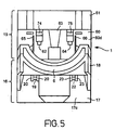
- the bottom of the translucent portion 4 is curved to define a crescent shaped opening 5 to a banknote path 6, which extends through the bezel 2 and the main body 1.
- the entry portion 6a of the banknote path flares vertically towards the opening 5.
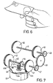
- the crescent shape of the opening 5 particularly adapts it for receiving banknotes held as shown in Figure 6.
- Two hook members 8 project rearwards from the lower portion of the main part 3.
- Two eye members 9 project rearwards from the upper portion of the main part 3.
- Two guide channels 10 also project rearwards from the upper portion of the main part 3 beside respective eye members 9.
- Fixing studs 11 project rearwards from each corner of the bezel 3. The roles of the hook and eye members 8, 9, the guide channels 10 and the fixing studs 11 will be explained below.
- the main body 1 comprises upper and lower sections 15,16 of plastics resin material.
- the lower section 16 is generally rectangular in plan and comprises a lower moulding 17 and an upper moulding 18.
- the lower moulding 17 has two low side walls 17a, 17b, a front wall 17c, a rear wall 17d and a bottom wall 17e.
- the rear bottom edge of the lower moulding 17 is chamfered.
- the front wall 17d forms substantially all of the front of the lower section 16.
- a vertically extending central portion of the front wall 17d is bowed outwards.
- a first short rod 19, supported by flanges 20 at either end, is located to one side of the top of the bowed portion of the front wall 17d.
- a second short rod 22, supported by flanges 23 at either end, is located on the other side of the bowed portion level with the first short rod 19.
- the upper moulding 18 comprises two side walls 18a, 18b, a rear wall 18c, an upper wall 18d and a shallow front wall 18e, and is open at the bottom.
- the upper wall 18d of the upper moulding 18 is inclined, rising towards the back of the validator, and projects forward of the front wall of the lower section 16.
- the upper wall 18d provides the floor of the banknote path 6 through the validator.
- the major part of the upper surface 18d is flat across its width. However, there is a transition region at the front of the lower section 16, where the upper wall 18d goes from having a transverse configuration matching the lower surface of the banknote path 6 at the back of the bezel 2 to being flat across its width.
- the upper wall 18d slopes upwards so that a banknote, inserted into the opening 5, is not stressed by the transition from bowed to flat as it travels along the banknote path 6.
- the junction between the upper wall 18d and the rear wall 18c is rounded.
- a first pair of slots 24, one either side of the banknote path's centre line, are provided in the upper wall 18d where it first becomes flat.
- a transverse slot 25 in the upper wall 18d extends substantially across the whole wide of the banknote path 6, immediately in front of the rounded meeting of the upper wall 18d and the rear wall 18c.
- a plurality of grooves 26 extends around the rounded meeting of the upper wall 18d and the rear wall 18c.
- Two slots 27, 28, which are aligned with the first pair of slots 24, are provided amongst the grooves 26.
- a pair of small rectangular apertures 29 are located outside respective ones of the slots 24.
- First and second tabs 30, 31 extend upwards from the rear margins of the side walls 18a, 18b of the upper moulding.
- the upper and lower mouldings 18, 17 are press-fitted together and held by a catch 32.
- the lower section 16 houses a pcb 33 that extends fully across the rear of the lower moulding 17, a first generally trapezial light guide 34 and a banknote drive mechanism.
- the light guide 34 is mounted at its narrow end to the pcb 33 and extends vertically so that its broad end is received in the transverse slot 25.
- the banknote drive mechanism comprises a first shaft 40 extending approximately two thirds of the way across the lower section 16 from its righthand side and a second similar shaft 41 lying parallel to the first shaft 40.
- a first tyred wheel 42 is mounted at the lefthand end of the first shaft 40 and a second tyred wheel 43 is mounted slightly to the right of the mid-point of the first shaft 40.
- the first and second tyred wheels 42, 43 project respectively through the first pair of slots 24 into the banknote path 6.
- a first spur gear 44 is mounted to the first shaft 40 midway between the first and second tyred wheels 42, 43.
- a cradle 45 pivotably depends from the first shaft 40.
- the cradle 45 comprises a cross-piece 45a and a pair of spaced arms 45b, 45c extending from the side edges of the cross-piece 45a and through which the first shaft 40 passes.
- An electric motor 46 is mounted to the cradle 45 by screws and the shaft of the motor 46 passes generally upwards through an aperture in the centre of the cross-piece 45a.
- a worm gear 47 is mounted to the motor's shaft and engages the first spur gear 44. Consequently, operation of the motor 46 causes the first shaft 40 to rotate.
- a second spur gear 47 is mounted to the righthand end of the first shaft 40.
- a third spur gear 48 is mounted directly to the lower section 16 and engages the second spur gear 47.
- a fourth spur gear 49 is mounted to the righthand end of the second shaft 41 and engages the third spur gear 48. Consequently, when the motor 46 operates, the first and second shafts 40, 41 are rotated in the same direction.
- Third and fourth tyred wheels 50, 51 are mounted to the second shaft 41 aligned respectively with the first and second tyred wheels 42, 43.
- the third and fourth tyred wheels 50, 51 project through respective slots 27, 28.
- the upper section 15 is generally rectangular in plan and comprises a lower moulding 60 and an upper moulding 61.
- the lower moulding 60 has a bottom wall 60a that corresponds to the form of the upper wall 18d of the lower section 16 and defines the upper wall of the banknote path 6.
- the lower moulding 60 also has two side walls 60b, 60c, a front wall 60d and a rear wall 60e.
- the front wall 60d is lower than the side walls 60b, 60c and has three vertical slots 62, 63, 64 extending from its upper edge.
- the central slot 63 enables electrical connections to be made to the bulb 7 in the bezel 2.
- the other slots 62, 64 are disposed symmetrically on either side of the central slot 63.
- a pair of vertical flanges 65, 66 are arranged one on each side of the three slots 62, 63, 64.
- a stub 67 projects from the rear margin of the lefthand side wall 60b and is received in an aperture in the tab 30.
- a similar stub 68 projects from the rear margin of the righthand side wall 60c and is received in an aperture in the tab 31.
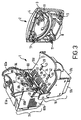
- the combination of the stubs 67, 68 and the tabs 30, 31 forms a hinge allowing the upper section 15 and the lower section 16 to be separated at the banknote path 6 for maintenance (see Figure 3).
- the rear wall 60e follows an arc through 90° from the back edges to the side walls 60b, 60c to the bottom of the upper section 15.
- a roller 69 extends across the rear of the upper section 15 within the arc of the rear wall 60e.
- the roller 69 has raised portions carrying tyres which are aligned with the third and fourth tyred wheels 50, 51.
- the lower portion of the rear wall 60e has three comb-shaped apertures 60f spaced across its width.
- the upper moulding 61 has a front wall 61a, a rear wall 61b, a low lefthand side wall 61c and an upper wall 61d.
- the righthand side, including part of the upper wall 61d, of the upper moulding is cut away.
- the upper wall 61 has a plurality of holes for indicator lights and to provide access to controls and is chamfered at its rear, upper edge.
- a D-shaped aperture 70 is provided centrally at the front of the upper wall 61d.
- a main catch member 71 comprises an inverted Y-shaped portion 72 and an integrally moulded, elongate spring element 73.
- the arms of the Y-shaped portion 72 have channels down either side which receive the sides of the outer slots 62, 64.
- a detent 74, 75 projects forward from each of the arms of the Y-shaped portion 72.
- the ends of the spring element 73 rest on the top edges of the side walls 60b, 60c of the lower moulding 60 of the upper section 15.
- a D-shaped flat 76 is located the top of the Y-shaped portion 72 and is received in the D-shaped aperture 70.
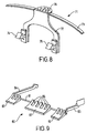
- an accept gate 80 comprises a shaft 81, rotatably mounted transversely immediately in front of the root of the rear wall 60e of the lower moulding 60 of the upper section 15, three banknote guiding structures 82 arranged along the shaft 81 and projecting backward, an indicator arm 83 projecting forward and upward from the lefthand end of the shaft 81 and a lever arm 84 projecting forward and upward from the other end of the shaft 81.
- the banknote guiding structures 82 each comprise a plurality of projections 85 linked at their distal ends.
- the projections 85 are generally in the form of right angle triangles, attached to the shaft 81 at their right angles.
- the upper edges of the projections 85 are slightly concave.
- the banknote guiding structures 82 project through the comb-shaped apertures 60f.
- the undersides of the banknote guiding structures 82 have a plurality of ribs 86 arranged to be received in the grooves 26.
- the distal end of the lever arm 84 is coupled to the top of the rear wall 60e by a spring (not shown).
- the spring is arranged to bias the accept gate 80 so that the ribs 86 are normally received in the grooves 26.
- the provision of the ribs 86 and the grooves 26 means that the accept gate 80 must be raised by an amount greater than the thickness of a banknote when a banknote passes under it. This means that the movement of the indicator arm 83 clearly signals the presence or absence of a banknote under the accept gate 80.
- the lower wall 60a of the lower moulding 60 has a pair of slots 87 aligned respectively with the slots 24 in the upper wall of the lower section 16.
- a fifth tyred wheel 88 is mounted in the lower moulding 60 so that it projects through the lefthand slot 87 in the lower wall of the upper section 15.
- a sixth tyred wheel 89 is mounted in the lower moulding 60 so that it projects through the righthand slot 87 in the lower wall of the upper section 15.
- a gear 90 is integrally moulded with the sixth tyred wheel 89 and engages a fifth spur gear (not shown).
- the fifth spur gear drives a toothed wheel 91 via a short shaft 92.
- the sixth tyred wheel 89 is held in a first yoke (not shown).
- the first yoke has vertical channels in the outer side faces of its legs which receive the ends of L-shaped flanges 94 projecting inwards from the front wall 60d of the lower moulding 60 of the upper section 15.
- the fifth tyred wheel 88 and the fifth spur gear are held by a second similar yoke 100 mounted to L-shaped flanges 94 projecting inwards from the front wall 60d.
- the toothed wheel 91 is suspended at one end of the short shaft 92 to the right of the second yoke 100.
- Small apertures 94 are provided in the lower wall 60a in alignment with the apertures 29 in the lower section 16.
- a transverse slot 95 is also provided in the lower wall 60a.
- a horizontal pcb 103 extends across the top of the lower moulding 60 of the upper section 15.
- a second trapezial light guide 104 is mounted at its narrow end to the horizontal pcb 103 and extends vertically downward so that its broad end is located in the transverse slot 95 in the lower wall 60a of the lower moulding 60.
- a vertical pcb 105 projects down from the horizontal pcb 103 and has five vertical slots which accommodate respectively the indicator arm 83, the yokes 100, the toothed wheel 91 and the lever arm 84. Photosensors are provided on the vertical pcb 105 for detecting the position of the indicator arm 83 and the movement of the toothed wheel 96.
- a magnetic sensor 108 is mounted in a recess in the underside of the upper wall 18d of the lower section 16, between the first and second tyred wheels 42, 43.
- the broad ends of the light guides 34, 104 make angles of 70° and 110° respectively to the front and rear faces of the light guides 34, 104. Consequently, light guided by the light guides 34,104 is not perpendicularly incident on a banknote 109 in the banknote path 6.
- the narrow ends 111 of the light guides 34, 104 have semi-circular cut-outs 112 which serve to spread light.being shone therein.
- the validator is mounted by first forming a rectangular aperture and four round holes in a panel.
- the bezel 2 is mounted to the panel by passing the fixing studs 11 through the round holes and fixing it in place with nuts on the fixing studs 11.
- the main body 1 is closed and offered up to the bezel 2 through the rectangular aperture.
- the hook members 8 are brought into engagement with the short rods 19, 22.
- the main body 1 is pivoted about the short rods 19, 22 so that the vertical flanges 65, 66 are received into the guide channels 10.
- the main body 1 is pivoted further until the detents 74, 75 engage respective eye members 9.
- the bezel 2 serves to both mount the main body 1 to a panel and to hold the upper and lower sections 15, 16 together.
- the main body 1 can be removed for maintenance by depressing the D-shaped flat 76, which causes the detents 74, 75 to disengage from the eye members 9, pivoting the main body 1 back about the short rods 19, 22 until the vertical flanges 65, 66 are clear and then unhooking the hook members 8 from the short rods 19, 22.
- the electronic circuits in the upper and lower sections 15, 16 are connected by a flying lead (not shown) outside the main body 1.
- the electronics of the validator is distributed over the pcbs 33, 103, 105 and comprises a microcontroller 300, which includes means for digitising five input signals, an EEPROM 301 storing program and banknote data, a RAM 302, a I/O device 303 and a bus 304 connecting the microcontroller 300, the EEPROM 301, the RAM 302 and the I/O device 303.
- the I/O device 303 provides the means whereby the EEPROM 301 can be reprogrammed and whereby control and reporting signals can be output from the validator.
- the motor control circuit 310 simply comprises a motor current supply switching device which is controlled by a signal from the microcontroller 300.
- the motion sensor 309 comprises an LED and a phototransistor. The LED and the phototransistor are arranged on opposite sides of the toothed wheel 96 on the vertical pcb 105 so that the teeth on the toothed wheel 96 interrupt the beam of light from the LED to the phototransistor.
- the first optical sensor 305 comprises a "white light” LED 350, a first phototransistor 351, a second phototransistor 352, a third phototransistor 353, a first filter 354, a second filter 355 and a third filter 356 all of which are mounted in one half of a hinged carrier 357.
- the second filter 355 is arranged in series with part of the first filter 354.
- the first and third filters have 3dB stopbands of 420-720nm.
- the second filter has 3dB stopbands of 480-540nm together with > 820nm.
- the "white light" LED 350 radiates a significant amount of light at infrared wavelengths.
- the narrow end of the first trapezial light guide 34 is received in the other half of the carrier 356.
- Light from the LED 350 is guided by the light guide 34 to the banknote path 6 and light reflected by a banknote in the banknote path 6 is guided by the light guide 34 to the first, second and third filters 354, 355, 356.
- the reflected light passing through the first filter 354 only is incident on the first phototransistor 351.
- the reflected light passing through the first filter 354 and the second filter 355 is incident on the second phototransistor 352.
- the reflected light passing through the third filter 354 only is incident on the third phototransistor 353.
- the second optical sensor 306 is similarly constructed in association with the second light guide 104.
- the first magnetic sensor 307 comprises first and second giant magneto-resistors 400, 401, mounted one above the other in a yoke 402, and control and output circuitry 403.
- the first giant magneto-resistor 400 is connected between the inputs of a first operational amplifier 404 and is supplied with a fixed bias voltage from a reference voltage source 405.
- the output of the first operational amplifier 404 is fed to the input of a low-pass filter 406.
- the low-pass filter 406 drives a bias coil 407, wound on the yoke 402.
- the output of the first operational amplifier 404 is also fed to the inverting input of a second operational amplifier 408 which is configured as a subtracter.
- the second giant magneto-resistor 401 is connected between the inputs of a third operational amplifier 409.
- the output of the third operational amplifier 409 is fed to the non-inverting input of the second operational amplifier 408.
- the output of the second operational amplifier 408 is amplified by a fourth operational amplifier 410 and applied to the second giant magneto-resistor 401 as its electrical bias.
- the fourth operational amplifier 410 is configured to alter the bias of the second giant magneto-resistor 401 so that the output of the second operational amplifier 408 will be zero. However, the response is arranged to be too slow to affect signals caused by a passing banknote 411.
- the output of the second operational amplifier 408 is also applied to the input of a two pole Butterworth low-pass filter 412 which has a first -3dB point at 15Hz.
- the output of the two pole low-pass filter 412 is fed to a two-stage amplifier 413.
- the bandwidths of both stages of the two-stage amplifier 413 are limited to ensure good noise performance.
- the output of the two-stage amplifier 413 is input to an analogue-to-digital converter input of the microcontroller 300.
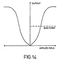
- Giant magneto-resistor devices have the characteristic shown in Figure 14. It is clear that such devices are most sensitive when a bias field is applied so that the device operates in the steepest part of its characteristic curve.
- the bias coil 407 is used to bias the giant magneto-resistors 400, 401 at this point.
- the bias field is set to the required value by adjusting the current through the bias coil 407. If the current is set to a constant value then any large external field will move the bias point and could saturate the sensor. To avoid this problem the current through the bias coil 407 is set by the feedback loop comprising the first giant magneto-resistor 400, the first operational amplifier 404 and the low-pass filter 406.
- the frequency response of this feedback loop has a low-pass characteristic with a first order roll-off from a -3dB point at 2Hz. This ensures that only constant and slowly changing magnetic fields are compensated for. In other words, the loop does not respond to signals caused by banknotes 411 passing the sensor.
- the two giant magneto-resistors 400, 401 are used together in order to compensate for faster changing fields. Both of the giant magneto-resistors 400, 401 are subject to the bias field produced by the bias coil 407.
- the output of the first giant magneto-resistor 400 is subtracted from the output of the second giant magneto-resistor 401 by the second operational amplifier 408. Consequently, any changing fields which act on both giant magneto-resistors 400, 401 will result in a zero output from the second operational amplifier 408.
- the second giant magneto-resistor 401 is closer to the banknote 411 and is subject to a much greater field from the banknote 411 (assuming that it is printed with magnetic ink) than the first giant magneto-resistor 400.
- the output of the second operational amplifier 408 is non-zero and representative of the magnetic field produced by the banknote 411.
- the characteristics of the giant magneto-resistors 400, 401 and their amplifiers 404, 409 must be matched.
- the sensitivity of a giant magneto-resistor is proportional to its electrical bias so, by fixing the bias of the first giant magneto-resistor 400 and varying the bias of the second giant magneto-resistor 401, their sensitivities can be matched.
- a second feedback loop comprising the third operational amplifier 409, the second operational amplifier 408 and the fourth operational amplifier 410, is used to set the electrical bias of the second giant magneto-resistor 401. This loop aims to set the variable bias so that the output of the second operational amplifier 408 is zero.
- the accept gate sensor 311 comprises an LED and a phototransistor mounted to the vertical pcb 105 so that the beam of light from the LED to the phototransistor is interrupted when the indicator arm 83 of the accept gate 80 drops as a banknote passes under the accept gate 80.
- the banknote detector 312 comprises first and second IR LEDs 450, 451 which are mounted to the vertical pcb 105.
- the IR LEDs 450, 451 are aligned with the small apertures 94, 29 in the upper and lower walls 60a, 18d of the banknote path 6.
- First and second photodetectors 452, 453 are located in the lower section 16 and are aligned with respective IR LEDs 450, 451.
- the outputs of the photodetectors 452, 453 are fed to the inputs of a NOR-gate 454.
- the output of the NOR-gate 454 is fed to the input of the microcontroller 300.
- the microcontroller 300 When the validator is installed for operation, the microcontroller 300 performs an initial test routine.
- the microcontroller 300 continuously monitors the output of the banknote detector 312 which will normally be low. However, when a banknote is inserted, the beams from the IR LEDs 450, 451 are broken and the microcontroller 300 receives a high signal from the banknote detector 312. The microcontroller 300 responds to this by driving the motor 46 so as to draw the banknote into the validator.
- a user must manually insert a banknote into the banknote path 6 until the leading edge of the banknote reaches the first and second tyred wheels 42, 43, at which point the banknote detector 312 output goes high and the motor 46 starts.
- the leading edge of the banknote is then gripped between the first and second tyred wheels 42, 43 and the fifth and sixth tyred wheels 88, 89, and then driven along the banknote path 6 by the first and second tyred wheels 42, 43.
- the microcontroller 300 begins to sample the output of the magnetic sensor unit 307.
- the microcontroller 300 also continuously monitors the output of the first optical sensor 305 until a change in one or both outputs indicates that the leading edge of the banknote has reached the first light guide 34. From this point on, the microprocessor 300 repeatedly samples and stores in the RAM 302 the outputs of the optical sensors 305, 306 and the magnetic sensor 307. The sampling terminates when one or both of the outputs of the second optical sensor 306 indicate that the banknote has completely passed the second light guide 104. The sampling of the outputs of the optical and magnetic sensors 305, 306, 307 is synchronised with the movement of the banknote along the banknote path 6 which is sensed by the motion sensor 309.
- the samples S1, S2 and S3 of the outputs of respectively the first, second and third phototransistors 351, 352, 353 of the optical sensors 305, 306 are processed according to stored algorithms to produce the values to be compared with stored reference values.
- the microcontroller 300 stops the motor 46. At this point, the banknote 500 extends under the accept gate 80 and is gripped between the third and fourth tyred wheels 50, 51 and the roller 68 ( Figure 16a).
- the microcontroller 300 determines whether the proffered banknote is acceptable.
- the optical and magnetic data derived from the optical and magnetic sensor outputs are then correlated with reference sample sets, stored in the EEPROM 301, by the microcontroller 300 (step s3). If the proffered banknote 500 is determined to be acceptable, the microcontroller 300 drives the motor 46 forward until the indicator arm 83 rises, indicating that the banknote has passed beyond the accept gate 80 ( Figure 16b). At this point, the banknote is held between the third and fourth tyred wheels 50, 51 and the roller 69. The motor 46 is then reversed and the banknote is driven backwards. However, the banknote cannot travel back along the banknote path 6 because the accept gate 80 has fallen. Instead, the banknote is guided up by the accept gate 80 so that is travels up and back so that it exits the back of the validator over the top of the roller 69 ( Figure 16c).
- the microcontroller 300 determines that it is not acceptable, the microcontroller 300 simply reverses the motor 46, driving the banknote back along the banknote path 6 to the user or would-be fraudster.
- the fifth tyred wheel 88 bears against and is driven by a banknote in the banknote path 6, or, if the banknote has passed, the first tyred wheel 42, causing the toothed wheel 96 of the motion sensor 309 to rotate.
- the microcontroller 300 monitors the output of motion sensor 309. If the validator is operating correctly, the microcontroller 300 should be receiving a stream of pulses from the motion sensor 309. The microcontroller 300 checks for the presence of pulses and the frequency of any pulse stream received. If no pulses are present or the frequency of the pulse stream is wrong, the microcontroller 300 determines that there is a fault in the motor 46 or a fraud is being attempted.
Landscapes
- Health & Medical Sciences (AREA)
- General Health & Medical Sciences (AREA)
- Toxicology (AREA)
- Physics & Mathematics (AREA)
- General Physics & Mathematics (AREA)
- Inspection Of Paper Currency And Valuable Securities (AREA)
- Seasonings (AREA)
- Saccharide Compounds (AREA)
Claims (7)
- Banknotenprüfer zum Prüfen eines beliebigen lagenartigen Objekts mit erkennbaren Merkmalen, wobei der Banknotenprüfer einen Banknotenweg (6), eine Rückschlagschranke (80) in dem Banknotenweg (6), umsteuerbare Banknotenantriebsmittel (46) zum Antreiben einer Banknote (500) in dem Banknotenweg (6), Banknotencharakteristika-Abtastmittel (300, 305, 306, 307) und verarbeitungsmittel (300, 309, 310) aufweist, die betrieben werden können, um das Banknotenantriebsmittel (46) während des Abtastens der Banknotencharakteristika durch das Banknotencharakteristika-Abtastmittel (300, 305, 306, 307) in einer ersten Richtung zu betreiben und danach das Banknotenantriebsmittel (46) umzusteuern, um eine Banknote (500) zurückzuweisen oder zu akzeptieren, wodurch das Verarbeitungsmittel (300, 309, 310) auf die Ausgabe des Banknotencharakteristika-Abtastmittels (300, 305, 306, 307) reagiert, um eine akzeptable Banknote zu identifizieren, und, falls eine Banknote (500) als akzeptabel erkannt worden ist, das Banknotenantriebsmittel (46) erst dann umzusteuern, nachdem die Banknote (500) an der Rückschlagschranke (80) vorbeigekommen ist.
- Banknotenprüfer nach Anspruch 1, bei dem die Rückschlagschranke (80) Banknotenführungsmittel einschließt, die zum Führen einer akzeptablen Banknote entlang eines Banknotenannahmewegs angeordnet sind, wenn das Banknotenantriebsmittel (46) umgesteuert worden ist.
- Banknotenprüfer nach Anspruch 2, bei dem die Rückschlagschranke (80) schwenkbar montierte Klappmittel umfasst, die in den Banknotenweg (6) hinein vorgespannt sind und sich in Bewegungsrichtung einer Banknote (500) erstrecken, bevor das Banknotenantriebsmittel (46) umgesteuert wird.
- Banknotenprüfer nach Anspruch 3, bei dem das Klappmittel durch Kontakt mit einer Banknote (500), die in einer Banknoten-Einführungsrichtung den Banknotenweg (6) passiert, in eine offene Position geschwenkt wird.
- Banknotenprüfer nach Anspruch 2, 3 oder 4, der eine drehbare Banknotenführung (69), die hinter der Rückschlagschranke (80) positioniert ist, und eine Banknotenführungswand einschließt, wobei das Banknotenantriebsmittel (46) ein Banknotenantriebsrad (51) unter der drehbaren Banknotenführung (69) einschließt, und eine akzeptable Banknote durch die Rückschlagschranke (80) und die Banknotenführungswand aufwärts und nach hinten über die drehbare Banknotenführung (69) geführt wird, wenn das Banknotenantriebsmittel (46) umgesteuert wird.
- Banknotenprüfer nach einem der vorhergehenden Ansprüche, bei dem die Rückschlagschranke (80) sich im Wesentlichen vollständig über die Breite des Banknotenwegs (6) erstreckt.
- Banknotenprüfer nach Anspruch 2 oder 3, bei dem die Unterseite des Klappmittels einen Vorsprung aufweist und der Banknotenweg (6) eine Vertiefung aufweist, wobei der Vorsprung in der Vertiefung aufgenommen wird, wenn sich das Klappmittel in seiner den Banknotenweg blockierenden Position befindet.
Priority Applications (7)
| Application Number | Priority Date | Filing Date | Title |
|---|---|---|---|
| DE69820412T DE69820412T2 (de) | 1998-02-19 | 1998-02-19 | Banknotenechtheitsprüfer |
| AT98301248T ATE256321T1 (de) | 1998-02-19 | 1998-02-19 | Banknotenechtheitsprüfer |
| EP98301248A EP0940778B1 (de) | 1998-02-19 | 1998-02-19 | Banknotenechtheitsprüfer |
| ES98301248T ES2212221T3 (es) | 1998-02-19 | 1998-02-19 | Dispositivo de validacion de papel moneda. |
| PCT/GB1999/000526 WO1999042959A1 (en) | 1998-02-19 | 1999-02-19 | Banknote validator |
| US09/402,750 US6392863B1 (en) | 1998-02-19 | 1999-02-19 | Banknote validator |
| US10/044,550 US7007788B2 (en) | 1998-02-19 | 2002-01-11 | Banknote validator |
Applications Claiming Priority (1)
| Application Number | Priority Date | Filing Date | Title |
|---|---|---|---|
| EP98301248A EP0940778B1 (de) | 1998-02-19 | 1998-02-19 | Banknotenechtheitsprüfer |
Publications (2)
| Publication Number | Publication Date |
|---|---|
| EP0940778A1 EP0940778A1 (de) | 1999-09-08 |
| EP0940778B1 true EP0940778B1 (de) | 2003-12-10 |
Family
ID=8234677
Family Applications (1)
| Application Number | Title | Priority Date | Filing Date |
|---|---|---|---|
| EP98301248A Expired - Lifetime EP0940778B1 (de) | 1998-02-19 | 1998-02-19 | Banknotenechtheitsprüfer |
Country Status (6)
| Country | Link |
|---|---|
| US (2) | US6392863B1 (de) |
| EP (1) | EP0940778B1 (de) |
| AT (1) | ATE256321T1 (de) |
| DE (1) | DE69820412T2 (de) |
| ES (1) | ES2212221T3 (de) |
| WO (1) | WO1999042959A1 (de) |
Families Citing this family (25)
| Publication number | Priority date | Publication date | Assignee | Title |
|---|---|---|---|---|
| EP0940778B1 (de) * | 1998-02-19 | 2003-12-10 | Innovative Technology Limited | Banknotenechtheitsprüfer |
| GB2355522A (en) * | 1999-10-19 | 2001-04-25 | Innovative Technology Ltd | Improvements in verifying printed security substrates |
| JP3518518B2 (ja) * | 2001-03-05 | 2004-04-12 | 松下電器産業株式会社 | 紙幣識別装置 |
| DE10137043A1 (de) * | 2001-07-31 | 2003-02-20 | Giesecke & Devrient Gmbh | Vorrichtung zur Untersuchung von Wertdokumenten |
| US7147222B2 (en) * | 2002-12-19 | 2006-12-12 | Eastman Kodak Company | Method and apparatus for registering sheet of arbitrary size |
| JP4247406B2 (ja) * | 2003-03-11 | 2009-04-02 | 旭精工株式会社 | 紙幣収納装置における状態検知装置 |
| JP4334911B2 (ja) * | 2003-05-28 | 2009-09-30 | ローレル精機株式会社 | 紙幣画像検出装置 |
| JP4334910B2 (ja) * | 2003-05-28 | 2009-09-30 | ローレル精機株式会社 | 紙幣画像検出装置 |
| ITTO20040484A1 (it) * | 2004-07-14 | 2004-10-14 | Olivetti Tecnost Spa | Apparecchiatura operativa su fogli introdotti verticalmente,in particolare una validatrice automatica di documenti, quali ad esempio assegni. |
| CA2516555A1 (en) | 2005-08-19 | 2007-02-19 | Cashcode Company Inc. | Banknote validator with banknote stack receiver |
| JP4656658B2 (ja) * | 2006-08-22 | 2011-03-23 | 株式会社ユニバーサルエンターテインメント | 紙幣処理装置 |
| JP4671932B2 (ja) * | 2006-08-22 | 2011-04-20 | 株式会社ユニバーサルエンターテインメント | 紙幣処理装置 |
| GB0702191D0 (en) * | 2007-02-05 | 2007-03-14 | Innovative Technology Ltd | Improvements Relating to Banknote Validation |
| USD574420S1 (en) * | 2007-04-05 | 2008-08-05 | De La Rue International Limited | Document handling apparatus |
| DE602008003359D1 (de) * | 2007-07-26 | 2010-12-23 | Toshiba Kk | Bilderzeugungsverfahren und persönliches Authentifizierungsmedium damit |
| JP2009080769A (ja) * | 2007-09-27 | 2009-04-16 | Sanden Corp | 紙幣識別装置 |
| US20110153439A1 (en) * | 2008-02-19 | 2011-06-23 | Emil Dimitrov | Computerized device for sale of goods and services |
| BG1167U1 (bg) * | 2008-02-19 | 2009-03-31 | Емил ДИМИТРОВ | Компютъризирано устройство за продажба на стоки и/или услуги |
| WO2009103132A1 (en) | 2008-02-19 | 2009-08-27 | Emil Dimitrov | Computerized device for sale of goods and services |
| DE102008027046A1 (de) * | 2008-06-06 | 2009-12-10 | Giesecke & Devrient Gmbh | Einrichtung zur Eingabe eines einzelnen Wertdokuments |
| ES2619728T3 (es) * | 2008-10-03 | 2017-06-26 | Crane Payment Innovations, Inc. | Discriminación y evaluación de monedas |
| WO2013027848A1 (ja) * | 2011-08-25 | 2013-02-28 | グローリー株式会社 | 紙葉類識別装置、紙葉類分光測定用ライトガイド及びライトガイドケース |
| DE102016211842B4 (de) * | 2016-06-30 | 2024-04-25 | Robert Bosch Gmbh | Bodenbearbeitungsgerät |
| CN108734261A (zh) * | 2017-08-31 | 2018-11-02 | 浙江商通电子有限公司 | 一种点验钞机 |
| GB2570706B (en) | 2018-02-05 | 2020-10-14 | Innovative Tech Ltd | A banknote validator |
Family Cites Families (23)
| Publication number | Priority date | Publication date | Assignee | Title |
|---|---|---|---|---|
| US3220549A (en) * | 1964-06-08 | 1965-11-30 | Vendit Inc | Method and apparatus for discriminating between desired and undesired documents |
| CH596617A5 (de) | 1975-07-24 | 1978-03-15 | Landis & Gyr Gmbh | |
| DE2713396A1 (de) * | 1977-03-24 | 1978-09-28 | Applied Photophysics Ltd | Verfahren und vorrichtung zur kennzeichnung oder identifizierung eines leuchtmaterial enthaltenden oder tragenden koerpers |
| US4342511A (en) * | 1980-08-20 | 1982-08-03 | International Business Machines Corporation | Illumination system having an efficient light guide |
| US4513439A (en) * | 1982-07-12 | 1985-04-23 | Ardac, Inc. | Security validator |
| US4881268A (en) * | 1986-06-17 | 1989-11-14 | Laurel Bank Machines Co., Ltd. | Paper money discriminator |
| CH689523A5 (de) * | 1989-05-01 | 1999-05-31 | Mars Inc | Pruefeinrichtung fuer ein blattfoermiges Gut. |
| GB8927225D0 (en) * | 1989-12-01 | 1990-01-31 | Ncr Co | Depository apparatus for envelopes and single sheets |
| DE4030836A1 (de) * | 1990-09-28 | 1992-04-02 | Kim Yoon Ok | Vorrichtung zur qualitativen und/oder quantitativen bestimmung der zusammensetzung einer zu analysierenden probe |
| CA2110681A1 (en) * | 1991-06-05 | 1992-12-10 | Peter Samuel Atherton | Optical memories incorporating diffraction gratings |
| US5378885A (en) * | 1991-10-29 | 1995-01-03 | Mars Incorporated | Unshielded magnetoresistive head with multiple pairs of sensing elements |
| JPH05159245A (ja) * | 1991-12-03 | 1993-06-25 | Sharp Corp | 複合型薄膜磁気ヘッド |
| US5662201A (en) * | 1992-04-16 | 1997-09-02 | Mars Incorporated | Banknote reader |
| DE69329186T2 (de) * | 1993-01-01 | 2001-04-05 | Canon Kk | Bildlesevorrichtung |
| US5422467A (en) * | 1993-01-15 | 1995-06-06 | Interbold | Article depositing apparatus |
| KR0164259B1 (ko) * | 1994-03-10 | 1999-03-20 | 오까다 마사하루 | 지폐처리장치 |
| JP3043239B2 (ja) * | 1994-10-07 | 2000-05-22 | シャープ株式会社 | 画像読み取り装置 |
| US6219205B1 (en) * | 1995-10-10 | 2001-04-17 | Read-Rite Corporation | High density giant magnetoresistive transducer with recessed sensor |
| US5966205A (en) * | 1997-07-01 | 1999-10-12 | Lj Laboratories, Llc | Method and apparatus for detecting and preventing counterfeiting |
| US5903339A (en) * | 1996-10-10 | 1999-05-11 | Coin Acceptors, Inc. | Light transmissive device for optical testing of transported bills |
| US5881196A (en) * | 1996-10-24 | 1999-03-09 | Phillips; Stephen | Waveguide security device |
| EP0918250B1 (de) * | 1997-11-20 | 2002-01-23 | Gretag Imaging Ag | Fotoelektrische Abtastvorrichtung für einen fotografischen Film |
| EP0940778B1 (de) * | 1998-02-19 | 2003-12-10 | Innovative Technology Limited | Banknotenechtheitsprüfer |
-
1998
- 1998-02-19 EP EP98301248A patent/EP0940778B1/de not_active Expired - Lifetime
- 1998-02-19 DE DE69820412T patent/DE69820412T2/de not_active Expired - Lifetime
- 1998-02-19 AT AT98301248T patent/ATE256321T1/de active
- 1998-02-19 ES ES98301248T patent/ES2212221T3/es not_active Expired - Lifetime
-
1999
- 1999-02-19 US US09/402,750 patent/US6392863B1/en not_active Expired - Lifetime
- 1999-02-19 WO PCT/GB1999/000526 patent/WO1999042959A1/en not_active Ceased
-
2002
- 2002-01-11 US US10/044,550 patent/US7007788B2/en not_active Expired - Lifetime
Also Published As
| Publication number | Publication date |
|---|---|
| ATE256321T1 (de) | 2003-12-15 |
| ES2212221T3 (es) | 2004-07-16 |
| US20020108891A1 (en) | 2002-08-15 |
| EP0940778A1 (de) | 1999-09-08 |
| US7007788B2 (en) | 2006-03-07 |
| DE69820412T2 (de) | 2004-05-27 |
| DE69820412D1 (de) | 2004-01-22 |
| US6392863B1 (en) | 2002-05-21 |
| WO1999042959A1 (en) | 1999-08-26 |
Similar Documents
| Publication | Publication Date | Title |
|---|---|---|
| EP0940778B1 (de) | Banknotenechtheitsprüfer | |
| US6044952A (en) | Multi-function optical sensor for a document acceptor | |
| US4154437A (en) | Multiple bill detector for currency dispensers | |
| US4850468A (en) | Money discriminating apparatus | |
| US8052145B2 (en) | Document handling apparatus | |
| US5806649A (en) | Paper currency validator | |
| US8276734B2 (en) | Bill validator with centering device | |
| US5657847A (en) | Banknote validator | |
| JP2966197B2 (ja) | 紙幣識別装置 | |
| CA2395726C (en) | Banknote validator with improved drive path | |
| US6223877B1 (en) | Coin validation apparatus | |
| JP4210466B2 (ja) | 判別装置 | |
| JP4261078B2 (ja) | 紙幣中心整合装置を備えた紙幣鑑別装置 | |
| JP2004227093A (ja) | 紙幣識別装置における紙幣検出装置 | |
| JPH05210779A (ja) | シート計数機 | |
| CN102037498B (zh) | 纸币识别装置 | |
| US6364087B1 (en) | Adaptive string detector for currency validators | |
| JP7750591B1 (ja) | 紙幣識別装置 | |
| JPH02147546A (ja) | 紙葉類判別装置 | |
| JP2005122427A (ja) | 紙幣識別装置 | |
| JP2536586Y2 (ja) | 紙葉類検出装置 | |
| JP2753051B2 (ja) | 通帳類処理装置 | |
| JPH1173532A (ja) | 紙票類識別装置 | |
| KR20050075153A (ko) | 지폐식별장치 | |
| JPH0743257B2 (ja) | 紙葉類の判定装置 |
Legal Events
| Date | Code | Title | Description |
|---|---|---|---|
| PUAI | Public reference made under article 153(3) epc to a published international application that has entered the european phase |
Free format text: ORIGINAL CODE: 0009012 |
|
| AK | Designated contracting states |
Kind code of ref document: A1 Designated state(s): AT BE CH DE DK ES FR GB GR IE IT LI NL PT |
|
| AX | Request for extension of the european patent |
Free format text: AL;LT;LV;MK;RO;SI |
|
| 17P | Request for examination filed |
Effective date: 20000308 |
|
| AKX | Designation fees paid |
Free format text: AT BE CH DE DK ES FR GB GR IE IT LI NL PT |
|
| 17Q | First examination report despatched |
Effective date: 20011219 |
|
| GRAP | Despatch of communication of intention to grant a patent |
Free format text: ORIGINAL CODE: EPIDOSNIGR1 |
|
| GRAS | Grant fee paid |
Free format text: ORIGINAL CODE: EPIDOSNIGR3 |
|
| GRAA | (expected) grant |
Free format text: ORIGINAL CODE: 0009210 |
|
| AK | Designated contracting states |
Kind code of ref document: B1 Designated state(s): AT BE CH DE DK ES FR GB GR IE IT LI NL PT |
|
| PG25 | Lapsed in a contracting state [announced via postgrant information from national office to epo] |
Ref country code: NL Free format text: LAPSE BECAUSE OF FAILURE TO SUBMIT A TRANSLATION OF THE DESCRIPTION OR TO PAY THE FEE WITHIN THE PRESCRIBED TIME-LIMIT Effective date: 20031210 Ref country code: LI Free format text: LAPSE BECAUSE OF FAILURE TO SUBMIT A TRANSLATION OF THE DESCRIPTION OR TO PAY THE FEE WITHIN THE PRESCRIBED TIME-LIMIT Effective date: 20031210 Ref country code: FR Free format text: LAPSE BECAUSE OF FAILURE TO SUBMIT A TRANSLATION OF THE DESCRIPTION OR TO PAY THE FEE WITHIN THE PRESCRIBED TIME-LIMIT Effective date: 20031210 Ref country code: CH Free format text: LAPSE BECAUSE OF FAILURE TO SUBMIT A TRANSLATION OF THE DESCRIPTION OR TO PAY THE FEE WITHIN THE PRESCRIBED TIME-LIMIT Effective date: 20031210 Ref country code: BE Free format text: LAPSE BECAUSE OF FAILURE TO SUBMIT A TRANSLATION OF THE DESCRIPTION OR TO PAY THE FEE WITHIN THE PRESCRIBED TIME-LIMIT Effective date: 20031210 |
|
| REG | Reference to a national code |
Ref country code: GB Ref legal event code: FG4D |
|
| REG | Reference to a national code |
Ref country code: CH Ref legal event code: EP |
|
| REG | Reference to a national code |
Ref country code: IE Ref legal event code: FG4D |
|
| REF | Corresponds to: |
Ref document number: 69820412 Country of ref document: DE Date of ref document: 20040122 Kind code of ref document: P |
|
| PG25 | Lapsed in a contracting state [announced via postgrant information from national office to epo] |
Ref country code: IE Free format text: LAPSE BECAUSE OF NON-PAYMENT OF DUE FEES Effective date: 20040219 |
|
| PG25 | Lapsed in a contracting state [announced via postgrant information from national office to epo] |
Ref country code: GR Free format text: LAPSE BECAUSE OF FAILURE TO SUBMIT A TRANSLATION OF THE DESCRIPTION OR TO PAY THE FEE WITHIN THE PRESCRIBED TIME-LIMIT Effective date: 20040310 Ref country code: DK Free format text: LAPSE BECAUSE OF FAILURE TO SUBMIT A TRANSLATION OF THE DESCRIPTION OR TO PAY THE FEE WITHIN THE PRESCRIBED TIME-LIMIT Effective date: 20040310 |
|
| NLV1 | Nl: lapsed or annulled due to failure to fulfill the requirements of art. 29p and 29m of the patents act | ||
| REG | Reference to a national code |
Ref country code: CH Ref legal event code: PL |
|
| REG | Reference to a national code |
Ref country code: ES Ref legal event code: FG2A Ref document number: 2212221 Country of ref document: ES Kind code of ref document: T3 |
|
| PLBE | No opposition filed within time limit |
Free format text: ORIGINAL CODE: 0009261 |
|
| STAA | Information on the status of an ep patent application or granted ep patent |
Free format text: STATUS: NO OPPOSITION FILED WITHIN TIME LIMIT |
|
| REG | Reference to a national code |
Ref country code: IE Ref legal event code: MM4A |
|
| 26N | No opposition filed |
Effective date: 20040913 |
|
| EN | Fr: translation not filed | ||
| PG25 | Lapsed in a contracting state [announced via postgrant information from national office to epo] |
Ref country code: IT Free format text: LAPSE BECAUSE OF NON-PAYMENT OF DUE FEES;WARNING: LAPSES OF ITALIAN PATENTS WITH EFFECTIVE DATE BEFORE 2007 MAY HAVE OCCURRED AT ANY TIME BEFORE 2007. THE CORRECT EFFECTIVE DATE MAY BE DIFFERENT FROM THE ONE RECORDED. Effective date: 20050219 |
|
| PG25 | Lapsed in a contracting state [announced via postgrant information from national office to epo] |
Ref country code: PT Free format text: LAPSE BECAUSE OF NON-PAYMENT OF DUE FEES Effective date: 20040510 |
|
| PGRI | Patent reinstated in contracting state [announced from national office to epo] |
Ref country code: IT Effective date: 20091201 |
|
| PGFP | Annual fee paid to national office [announced via postgrant information from national office to epo] |
Ref country code: AT Payment date: 20131211 Year of fee payment: 17 |
|
| REG | Reference to a national code |
Ref country code: AT Ref legal event code: MM01 Ref document number: 256321 Country of ref document: AT Kind code of ref document: T Effective date: 20150219 |
|
| PG25 | Lapsed in a contracting state [announced via postgrant information from national office to epo] |
Ref country code: AT Free format text: LAPSE BECAUSE OF NON-PAYMENT OF DUE FEES Effective date: 20150219 |
|
| PGFP | Annual fee paid to national office [announced via postgrant information from national office to epo] |
Ref country code: GB Payment date: 20161216 Year of fee payment: 20 |
|
| PGFP | Annual fee paid to national office [announced via postgrant information from national office to epo] |
Ref country code: DE Payment date: 20170303 Year of fee payment: 20 |
|
| PGFP | Annual fee paid to national office [announced via postgrant information from national office to epo] |
Ref country code: IT Payment date: 20161220 Year of fee payment: 20 Ref country code: ES Payment date: 20170201 Year of fee payment: 20 |
|
| REG | Reference to a national code |
Ref country code: DE Ref legal event code: R071 Ref document number: 69820412 Country of ref document: DE |
|
| REG | Reference to a national code |
Ref country code: GB Ref legal event code: PE20 Expiry date: 20180218 |
|
| PG25 | Lapsed in a contracting state [announced via postgrant information from national office to epo] |
Ref country code: GB Free format text: LAPSE BECAUSE OF EXPIRATION OF PROTECTION Effective date: 20180218 |
|
| REG | Reference to a national code |
Ref country code: ES Ref legal event code: FD2A Effective date: 20180525 |
|
| PG25 | Lapsed in a contracting state [announced via postgrant information from national office to epo] |
Ref country code: ES Free format text: LAPSE BECAUSE OF EXPIRATION OF PROTECTION Effective date: 20180220 |