EP0940640A2 - Gehäuse für Verbrennungskessel und Kessel mit einem solchen Gehäuse - Google Patents
Gehäuse für Verbrennungskessel und Kessel mit einem solchen Gehäuse Download PDFInfo
- Publication number
- EP0940640A2 EP0940640A2 EP99104382A EP99104382A EP0940640A2 EP 0940640 A2 EP0940640 A2 EP 0940640A2 EP 99104382 A EP99104382 A EP 99104382A EP 99104382 A EP99104382 A EP 99104382A EP 0940640 A2 EP0940640 A2 EP 0940640A2
- Authority
- EP
- European Patent Office
- Prior art keywords
- shell
- cover
- boiler
- shells
- combustion
- Prior art date
- Legal status (The legal status is an assumption and is not a legal conclusion. Google has not performed a legal analysis and makes no representation as to the accuracy of the status listed.)
- Withdrawn
Links
- 238000002485 combustion reaction Methods 0.000 title claims abstract description 20
- 239000000463 material Substances 0.000 claims abstract description 17
- 239000004033 plastic Substances 0.000 claims abstract description 16
- 229920003023 plastic Polymers 0.000 claims abstract description 16
- 239000003517 fume Substances 0.000 claims abstract description 7
- 239000002184 metal Substances 0.000 claims description 10
- 230000007423 decrease Effects 0.000 claims description 2
- 239000012780 transparent material Substances 0.000 claims 1
- 238000009413 insulation Methods 0.000 description 9
- XLYOFNOQVPJJNP-UHFFFAOYSA-N water Substances O XLYOFNOQVPJJNP-UHFFFAOYSA-N 0.000 description 8
- 239000007789 gas Substances 0.000 description 3
- 238000004519 manufacturing process Methods 0.000 description 2
- 229920000642 polymer Polymers 0.000 description 2
- 230000003014 reinforcing effect Effects 0.000 description 2
- 239000004743 Polypropylene Substances 0.000 description 1
- 239000004793 Polystyrene Substances 0.000 description 1
- 230000000295 complement effect Effects 0.000 description 1
- 239000002131 composite material Substances 0.000 description 1
- 238000005034 decoration Methods 0.000 description 1
- 239000003822 epoxy resin Substances 0.000 description 1
- LNEPOXFFQSENCJ-UHFFFAOYSA-N haloperidol Chemical compound C1CC(O)(C=2C=CC(Cl)=CC=2)CCN1CCCC(=O)C1=CC=C(F)C=C1 LNEPOXFFQSENCJ-UHFFFAOYSA-N 0.000 description 1
- 238000010438 heat treatment Methods 0.000 description 1
- 239000011810 insulating material Substances 0.000 description 1
- 239000007769 metal material Substances 0.000 description 1
- 238000012544 monitoring process Methods 0.000 description 1
- 229920000647 polyepoxide Polymers 0.000 description 1
- -1 polypropylene Polymers 0.000 description 1
- 229920001155 polypropylene Polymers 0.000 description 1
- 229920002223 polystyrene Polymers 0.000 description 1
- 229920002635 polyurethane Polymers 0.000 description 1
- 239000004814 polyurethane Substances 0.000 description 1
Images

Classifications
-
- F—MECHANICAL ENGINEERING; LIGHTING; HEATING; WEAPONS; BLASTING
- F24—HEATING; RANGES; VENTILATING
- F24H—FLUID HEATERS, e.g. WATER OR AIR HEATERS, HAVING HEAT-GENERATING MEANS, e.g. HEAT PUMPS, IN GENERAL
- F24H9/00—Details
- F24H9/02—Casings; Cover lids; Ornamental panels
Definitions
- the present invention relates to a cover for a combustion boiler.
- the present invention relates to a cover for a domestic combustion boiler, to which the present invention refers explicitly without loss of its generality thereby.
- Combustion boilers usually have a central body comprising a combustion chamber, a heat exchanger for transferring the energy between the fumes produced by the combustion and a mass of water, and a fume intake/aspiration flue.
- the covers of the aforesaid boilers comprise panels of sheet metal attached to each other to form spaces enclosing the associated central bodies. This type of cover also has a hinged panel which is movable between a closed position and an open position in order to access the aforesaid central body.
- the metal panels of the cover are relatively rigid and are connected to support elements located inside the cover in order to support the central body of the boiler and, therefore, they also form the supporting frame of the boiler itself.
- the metal panels of known type are attached with increasing frequency to panels made from insulating material which provide both acoustic and thermal insulation.
- boiler covers which insulate the boilers acoustically and thermally are particularly important nowadays.
- boilers are increasingly installed in kitchens, bathrooms or, in some cases, in the living rooms of a house and, therefore, the requirement of preventing the boilers from generating any disturbance to the environment in which they are installed becomes more important.
- the requirement also exists of providing aesthetically attractive boiler covers which adapt to the style of decoration in the part of the house in which the boilers are installed.
- the known covers are unable to satisfy the requirements described above due to the fact that the metal panels cannot be shaped simply and economically in order to achieve particular aesthetic shapes. Furthermore, the covers comprising the metal panels are also inefficient from the point of view of thermal and acoustic insulation if there are no further insulating panels, which must be fitted inside the covers and which increase the manufacturing costs of the boilers.
- the object of the present invention is therefore to provide a cover which is free from the disadvantages described above.
- a cover for a combustion boiler being characterised in that it includes first and second half-shells connectable to each other to form the said cover, and in that the said first and second half-shells are manufactured from plastics material.
- This arrangement is particularly advantageous due to the fact that, on the one hand, the plastics material is easily workable in order to provide the cover with the particular aesthetic shapes and has a greater thermal and acoustic insulating capacity than the metal materials and, on the other hand, the half-shells have a greater structural rigidity than the simple flat walls. Therefore, the synergy deriving from the use of the plastics material together with the use of a shell shape formed from two half-shells ensures the necessary rigidity for the cover such that this latter is able to act as a frame, in addition to which it is easy to work in order to obtain the desired aesthetic shapes, and improved thermal and acoustic insulation is ensured.
- the reference numeral 1 indicates a wall-mounted gas combustion boiler for heating a mass of water circulating in a circuit of known type, not illustrated.
- the boiler 1 comprises a central body 2, a cover 3 and a control panel 4.
- the boiler 1 is connected to a gas supply pipe 5, a cold water supply pipe 6, a hot water outlet pipe 7 and an exhaust pipe 8 for the fumes produced by the gas combustion.
- the pipes 6 and 7 form part of the aforesaid known circuit, not illustrated.
- the body 2 comprises a combustion chamber 9, a heat exchanger 10 located above the combustion chamber 9, and a fume aspiration hood 11 located above the heat exchanger 10, connected to the fume aspiration pipe 8 and attached to an aspiration fan 12.
- the body 2 also includes a water pump 13 located below the chamber 9 and connected to the water supply pipe 6.
- the control panel 4 comprises a support plate 14, a thermometer 15, a pressure switch 16, a series of indicator lights 17 and control knobs 18.
- the thermometer 15 is connected to a sensor of known type, not illustrated, for detecting the temperature of the water leaving the heat exchanger 10, while the pressure switch 16 is connected to a sensor of known type, not illustrated, for detecting the water pressure in the aforesaid circuit.
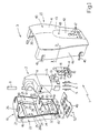
- the cover 3 comprises a half-shell 19 and a half-shell 20 made from relatively rigid plastics material, that is, the half-shells 19 and 20 are formed from a plastics material of a density which ensures not only that the shape of the half-shells 19 and 20 is stable, but that they are also capable of supporting predetermined loads.
- the half-shells 19 and 20 are connectable to each other to form the cover 3.
- the half-shell 19 is formed as a single block of plastics material and comprises an inner surface 21, an outer surface 22, a substantially flat rear wall 23 and a substantially annular side wall 24 located along the perimeter of the wall 23.
- the wall 23 is suitable for locating against a wall and has a central aperture 25, while the side wall 24 has a slot 26 housing the pipe 8.
- the half-shell 19 comprises an upper plate 27, a central plate 28 and a lower plate 29, all of which are formed in metal, are elongate in shape and are disposed horizontally through the central aperture 25.
- the plates 27, 28 and 29 have respective opposite ends which are embedded in the plastics material of the half-shell 19 which has reinforcing elements 30 made from plastics material at each of the aforesaid ends.
- the upper plate 27 and the lower plate 29 have respective holes 31 and 32 which are used to attach the boiler 1 to a wall by means of screws of known type, not illustrated, or by means of expansion plugs of known type, not illustrated.
- the central plate 28 is coupled in known way, not illustrated, to a metal bracket 33 which has a substantially horizontal surface 34 for supporting the combustion chamber 9, and slots 35 and 36 housing the known supply pipes, not shown, located between the pump 13 and the chamber 9.
- the bracket 33 supports the central body 2 and is rigidly connected to the half-shell 19 which acts as the support frame for the boiler 1.
- the half-shell 19 also includes two guides 37 which are located at the base of the half-shell 19 itself and extend transversely with respect to the rear wall 23.
- the guides 37 have respective ends which are embedded in the plastics material of the half-shell 19 which has reinforcing elements 38 at the aforesaid ends.
- the half-shell 20 is formed as a single piece of plastics material and includes an inner surface 39 and an outer surface 40.
- the half-shell 20 also includes a front wall 41 comprising a concave portion 42 connected to a convex portion 43, and a shaped side wall 44 disposed substantially along the perimeter of the wall 42, which is connectable to the side wall 24 of the half-shell 19.
- the side wall 24 of the half-shell 19 includes an edge 24a complementary in shape to an edge 42a formed on the side wall 42 of the half-shell 20 so that when the half-shell 20 is connected to the half-shell 19, the edges 24a and 42a interpenetrate one another.
- the half-shell 20 has snap-engagement hooks 45 which are distributed along the side wall 44 and engage respective slots 46 distributed along the side wall 24 of the half-shell 19.
- the concave portion 42 of the front wall 41 has a plurality of holes 47 through which the thermometer 13, the pressure switch 16 and the indicator lights 17 are visible, and through which the control knobs 18 project.
- the concave portion 42 has a further hole 48 for monitoring the combustion chamber 9, that is, for so-called flame control.
- the cover 3 includes a base closure panel 49 which is fixed to the half-shell 19 by screws 50.
- the panel 49 has pre-weakened zones 51 which can easily be removed in the event that it is necessary to form apertures of dimensions corresponding to the dimensions of the pipes 5, 6 and 7.
- polymeric materials In order to manufacture the half-shells 19 and 20, polymeric materials have particularly advantageous characteristics in comparison with the other plastics materials.
- polyurethane, polypropylene, polystyrene, polyethylemethacrylate and the composite epoxy resins with polymers ensure, on the one hand, good workability and, on the other hand, have good characteristics of mechanical rigidity as well as satisfactory thermal and acoustic insulation characteristics.
- the inner surfaces 21 and 39 of the respective half-shells 19 and 20 are relatively rough, while the respective outer surfaces 22 and 40 are relatively smooth.
- the inner roughness improves the acoustic insulation.
- the inner walls 21 and 39 are rusticated in order to improve the acoustic insulation.
- the front wall 41 of the half-shell 20 is located between the inner surface 39 and an outer surface 40, and comprises a portion 52 adjacent the surface 40 and a portion 53 adjacent the wall 39.
- the portion 52 has a relatively high density which ensures the rigidity of the half-shell 20, while the portion 53 has a relatively low density in order to achieve the thermal and acoustic insulation.
- the portion 52 and 53 are theoretically separated in Figure 2 by the broken line 54 which separates the portion 53 which confers the structural rigidity on the half-shell 20 from the portion 53 which ensures the thermal and acoustic insulation.
- the density of the wall 41 gradually decreases from the outer surface 40 towards the inner surface 39.
- the variation in density across the wall 41 is made possible by using the above indicated polymers which are used to form both the half shell 19 and the half shell 20, and are worked in order to provided a degree of expansion which gradually increases from the respective outer surfaces 22 and 40 towards the respective inner surfaces 21 and 39.
- the concave portion is covered by a transparent cover which is movable between a closed position and an open position.
Landscapes
- Engineering & Computer Science (AREA)
- Physics & Mathematics (AREA)
- Thermal Sciences (AREA)
- Chemical & Material Sciences (AREA)
- Combustion & Propulsion (AREA)
- Mechanical Engineering (AREA)
- General Engineering & Computer Science (AREA)
- Cookers (AREA)
- Housings, Intake/Discharge, And Installation Of Fluid Heaters (AREA)
- Solid-Fuel Combustion (AREA)
Applications Claiming Priority (2)
| Application Number | Priority Date | Filing Date | Title |
|---|---|---|---|
| IT98BO000130A IT1299881B1 (it) | 1998-03-05 | 1998-03-05 | Mantello di copertura di una caldaia a combustione e caldaia provvista di tale mantello. |
| ITBO980130 | 1998-03-05 |
Publications (2)
| Publication Number | Publication Date |
|---|---|
| EP0940640A2 true EP0940640A2 (de) | 1999-09-08 |
| EP0940640A3 EP0940640A3 (de) | 2000-10-11 |
Family
ID=11342981
Family Applications (1)
| Application Number | Title | Priority Date | Filing Date |
|---|---|---|---|
| EP99104382A Withdrawn EP0940640A3 (de) | 1998-03-05 | 1999-03-04 | Gehäuse für Verbrennungskessel und Kessel mit einem solchen Gehäuse |
Country Status (2)
| Country | Link |
|---|---|
| EP (1) | EP0940640A3 (de) |
| IT (1) | IT1299881B1 (de) |
Cited By (5)
| Publication number | Priority date | Publication date | Assignee | Title |
|---|---|---|---|---|
| WO2016142177A1 (de) * | 2015-03-09 | 2016-09-15 | Robert Bosch Gmbh | Gehäuse für eine wärmezelle |
| WO2019064957A1 (ja) * | 2017-09-26 | 2019-04-04 | 株式会社ノーリツ | 温水装置 |
| JP2019060521A (ja) * | 2017-09-26 | 2019-04-18 | 株式会社ノーリツ | 温水装置 |
| EP3702690A1 (de) * | 2019-02-28 | 2020-09-02 | Gerdes Holding GmbH & Co. KG | Durchlauferhitzer mit einem gehäuse |
| US20220364765A1 (en) * | 2021-05-12 | 2022-11-17 | Rinnai Corporation | Combustion apparatus |
Family Cites Families (5)
| Publication number | Priority date | Publication date | Assignee | Title |
|---|---|---|---|---|
| DE1679779A1 (de) * | 1965-05-13 | 1971-08-12 | Vaillant Joh Kg | Wassererhitzer mit abgedichtetem Geblaesebrenner |
| US3521604A (en) * | 1968-01-29 | 1970-07-28 | Smith Corp A O | Vessel having a foam polyurethane outer layer |
| NL7415810A (nl) * | 1974-02-26 | 1975-08-28 | Bosch Siemens Hausgeraete | Technisch huishoudtoestel, in het bijzonder een boiler. |
| CH624202A5 (en) * | 1977-03-25 | 1981-07-15 | Semperit Ag | Heat-insulation shell, especially for hot-water containers and hot-water pipelines |
| JPH0931371A (ja) * | 1995-07-21 | 1997-02-04 | Nippon Paint Co Ltd | 塗料組成物、塗装板および装飾性塗装板の製造方法 |
-
1998
- 1998-03-05 IT IT98BO000130A patent/IT1299881B1/it active IP Right Grant
-
1999
- 1999-03-04 EP EP99104382A patent/EP0940640A3/de not_active Withdrawn
Cited By (9)
| Publication number | Priority date | Publication date | Assignee | Title |
|---|---|---|---|---|
| WO2016142177A1 (de) * | 2015-03-09 | 2016-09-15 | Robert Bosch Gmbh | Gehäuse für eine wärmezelle |
| CN107407500A (zh) * | 2015-03-09 | 2017-11-28 | 罗伯特·博世有限公司 | 用于热电池的壳体 |
| CN107407500B (zh) * | 2015-03-09 | 2020-11-03 | 罗伯特·博世有限公司 | 用于热电池的壳体 |
| WO2019064957A1 (ja) * | 2017-09-26 | 2019-04-04 | 株式会社ノーリツ | 温水装置 |
| JP2019060521A (ja) * | 2017-09-26 | 2019-04-18 | 株式会社ノーリツ | 温水装置 |
| CN111094865A (zh) * | 2017-09-26 | 2020-05-01 | 株式会社能率 | 热水装置 |
| US11512871B2 (en) * | 2017-09-26 | 2022-11-29 | Noritz Corporation | Water heater |
| EP3702690A1 (de) * | 2019-02-28 | 2020-09-02 | Gerdes Holding GmbH & Co. KG | Durchlauferhitzer mit einem gehäuse |
| US20220364765A1 (en) * | 2021-05-12 | 2022-11-17 | Rinnai Corporation | Combustion apparatus |
Also Published As
| Publication number | Publication date |
|---|---|
| IT1299881B1 (it) | 2000-04-04 |
| EP0940640A3 (de) | 2000-10-11 |
| ITBO980130A1 (it) | 1999-09-05 |
| ITBO980130A0 (it) | 1998-03-05 |
Similar Documents
| Publication | Publication Date | Title |
|---|---|---|
| US8347950B2 (en) | Modular room heat exchange system with light unit | |
| US4221441A (en) | Prefabricated kitchen-bath utility system | |
| EP0940640A2 (de) | Gehäuse für Verbrennungskessel und Kessel mit einem solchen Gehäuse | |
| US6293697B1 (en) | Housing for HVAC control unit | |
| KR20040036051A (ko) | 난방관 배관용 단열보드 | |
| US5263114A (en) | Ceiling element for regulating temperature | |
| KR200300616Y1 (ko) | 난방관 배관용 단열보드 | |
| JPH0712381A (ja) | 住宅用給排気装置 | |
| JPH09178236A (ja) | システムキッチンの給気構造 | |
| JPH0114815Y2 (de) | ||
| JPH0118048Y2 (de) | ||
| AU2003100619A4 (en) | Modular appliance | |
| KR830002285Y1 (ko) | 온장고를 내장한 보일러 | |
| JPS622413Y2 (de) | ||
| SE9404381L (sv) | Värmeackumulerande eldstad sammansatt av separata förtillverkade modulelement | |
| WO1995018942A1 (en) | A radiator housing | |
| JPH08114024A (ja) | 調理器具収納ユニット | |
| JPS598130Y2 (ja) | 給湯器 | |
| JP2006020832A (ja) | システムキッチン組み込み式冷蔵庫 | |
| EP1891377A2 (de) | Garvorrichtung | |
| JPH058413Y2 (de) | ||
| JPH0451656Y2 (de) | ||
| GB2184141A (en) | Modular building element comprising energy-using appliance | |
| JPS6035010Y2 (ja) | 湯沸器におけるコントロ−ルボックスの取付装置 | |
| JPS62137013A (ja) | 厨房装置 |
Legal Events
| Date | Code | Title | Description |
|---|---|---|---|
| PUAI | Public reference made under article 153(3) epc to a published international application that has entered the european phase |
Free format text: ORIGINAL CODE: 0009012 |
|
| AK | Designated contracting states |
Kind code of ref document: A2 Designated state(s): BE DE FR IT |
|
| AX | Request for extension of the european patent |
Free format text: AL;LT;LV;MK;RO;SI |
|
| PUAL | Search report despatched |
Free format text: ORIGINAL CODE: 0009013 |
|
| AK | Designated contracting states |
Kind code of ref document: A3 Designated state(s): AT BE CH CY DE DK ES FI FR GB GR IE IT LI LU MC NL PT SE |
|
| AX | Request for extension of the european patent |
Free format text: AL;LT;LV;MK;RO;SI |
|
| 17P | Request for examination filed |
Effective date: 20010402 |
|
| AKX | Designation fees paid |
Free format text: BE DE FR IT |
|
| 17Q | First examination report despatched |
Effective date: 20030127 |
|
| STAA | Information on the status of an ep patent application or granted ep patent |
Free format text: STATUS: THE APPLICATION IS DEEMED TO BE WITHDRAWN |
|
| 18D | Application deemed to be withdrawn |
Effective date: 20030807 |