EP0939474A2 - Batterielader und Ladeverfahren - Google Patents
Batterielader und Ladeverfahren Download PDFInfo
- Publication number
- EP0939474A2 EP0939474A2 EP99102765A EP99102765A EP0939474A2 EP 0939474 A2 EP0939474 A2 EP 0939474A2 EP 99102765 A EP99102765 A EP 99102765A EP 99102765 A EP99102765 A EP 99102765A EP 0939474 A2 EP0939474 A2 EP 0939474A2
- Authority
- EP
- European Patent Office
- Prior art keywords
- battery
- temperature
- charging
- current
- temperature rise
- Prior art date
- Legal status (The legal status is an assumption and is not a legal conclusion. Google has not performed a legal analysis and makes no representation as to the accuracy of the status listed.)
- Granted
Links
Images


Classifications
-
- H—ELECTRICITY
- H02—GENERATION; CONVERSION OR DISTRIBUTION OF ELECTRIC POWER
- H02J—ELECTRIC POWER NETWORKS; CIRCUIT ARRANGEMENTS OR SYSTEMS FOR SUPPLYING OR DISTRIBUTING ELECTRIC POWER; SYSTEMS FOR STORING ELECTRIC ENERGY
- H02J7/00—Circuit arrangements for charging or discharging batteries or for supplying loads from batteries
- H02J7/90—Regulation of charging or discharging current or voltage
- H02J7/971—Regulation of charging or discharging current or voltage the charge cycle being controlled or terminated in response to non-electric parameters
- H02J7/975—Regulation of charging or discharging current or voltage the charge cycle being controlled or terminated in response to non-electric parameters in response to temperature
- H02J7/977—Regulation of charging or discharging current or voltage the charge cycle being controlled or terminated in response to non-electric parameters in response to temperature of the battery
Definitions
- the present invention relates to a battery charger and a charging method for charging a battery.
- the present invention relates, in particular, to a battery charger and a charging method suitable for charging a battery, such as a nickel metal hydride battery, which accumulates a large amount of heat during charging.
- a charging-type battery which can be repeatedly charged is recently used as a power source for a power tool, for example.
- a nickel metal hydride battery is widely used as the power tool battery of this type.
- a battery charger for rapidly charging the battery with high current is used. That is, while a battery is rapidly charged for about 20 minutes and, a power tool can be continuously used while replacing a currently used battery with another one which has been charged.
- the inventor of the present invention studied ways to improve the performance of a power tool by using, as a battery, a nickel metal hydride battery.
- the nickel metal hydride battery can provide higher capacity than a nickel-cadmium battery, a large amount of heat is generated during charging. If the battery temperature becomes high due to the generated heat, the electrodes and separators of cells within the battery deteriorate and battery life is shortened. Due to this, the nickel metal hydride battery cannot be rapidly charged with high current unlike the nickel-cadmium battery.
- the nickel metal hydride battery is more sensitive to overcharge than the nickel-cadmium battery and overcharging makes the battery life shorter. For that reason, it is required to avoid overcharging the nickel metal hydride battery.
- charging current and discharging current are integrated and a battery is charged based on the integrated value. Thus, the battery can be fully charged. In case of charging a battery for equipment such as the above-stated power tool which requires replacing one battery with another, however, it has been difficult to fully charge the battery without overcharging it.
- the invention recited in claims 1 and 3 has been made to solve the above-stated disadvantages and has an object to provide a battery charger and a charging method capable of charging a battery for a short period of time while suppressing battery temperature from rising.
- the invention recited in claims 2 and 4 has been made to solve the above-stated disadvantages and has an object to provide a battery charger and a charging method capable of fully charging a battery without fear of an overcharge.
- the battery charger recited in claim 1 is technically characterized by comprising:
- the battery charger recited in claim 2 is technically characterized by comprising:
- the charging method recited in claim 3 is technically characterized by comprising:
- the charging method recited in claim 4 is technically characterized by comprising:
- charging current is controlled using a map for mapping an allowable value of current with which a battery can be charged while suppressing battery temperature from rising based on battery temperature and battery temperature rise. That is, the map is retrieved from the battery temperature and temperature rise.
- the allowable value of current, with which the battery can be charged while suppressing the battery temperature from rising, is obtained.
- the battery is charged with the allowable current thus obtained.
- charging current is controlled using a map for mapping an allowable value of current with which a battery can be charged while suppressing battery temperature from rising based on battery temperature and battery temperature rise. That is, the map is retrieved from the battery temperature and temperature rise.
- the allowable value of current, with which the battery can be charged while suppressing the battery temperature from rising, is obtained. Consequently, the battery is charged with the allowable current thus obtained.
- the completion of charging is determined, in particular, based on whether or not a temperature rise is relatively large and whether or not relatively low current is outputted from the map with high frequency. That is, based on whether or not temperature rise is large and whether or not the rise is large even if charging current is decreased. Due to this, it is possible to fully charge the battery without fear of overcharging and without being influenced by the remaining battery capacity, temperature and the like.
- FIG. 1 shows a battery charger 10 in one embodiment according to the present invention.
- FIG. 2 shows a battery pack 50 charged by the battery charger.
- FIG. 3 shows a battery drill 70 driven by the battery pack 50.
- the battery pack 50 including a nickel metal hydride battery, consists of a generally cylindrical fitted section 52 and a generally prismatic base 56.
- a key-shaped key section 54 is formed on the side surface of the fitted section 52.
- the first input terminal t1 connected to the cathode of the battery, the second input terminal t2 connected to the anode therein and the third terminal t3 connected to a temperature sensor consisting of a thermistor are provided on the upper portions of the fitted section 52.
- a fitting hole 12 for fitting the fitted section 52 of the battery pack 50 is formed at the battery charger 10 for charging the battery pack 50.
- a key way 14 for introducing the key section 54 of the fitted section 52 is formed on the sidewall of the fitting hole 12.
- the fitting hole 12 is integral with a housing 16 which constitutes the battery charger 10 and is made from resin.
- the key section 54 is provided at the fitted section 52 of the battery pack 50 and the fitted hole 12 of the battery charger 10 is provided with the key way 14. This thereby prevents the battery pack 50 from being fitted in an incorrect manner.
- First to third output terminals (not shown) are provided at the bottom of the fitting hole 12 to make contact with the first to third terminals t1, t2 and t3 of the battery pack 50.
- An LED lamp 18 is provided on the top of the battery charger 10 to indicate that the battery is being charged.
- a fitting hole 72 for fitting the fitted section 52 of the battery pack 59 is provided in the battery drill 70.
- a motor (not shown) is driven to rotate a chuck 76. If the battery drill 70 is in use, a plurality of batteries which have been charged within the battery pack 50 are sequentially used to allow continuous operation.
- the battery charger 10 in this embodiment is designed to be capable of rapidly charging the battery pack 50 in approximately 20 minutes.
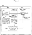
- FIG. 4 shows the configuration of a control circuit within the battery charger 10 .
- the control circuit 30 consists of a temperature detection section 38 for detecting the temperature of a battery from an output value of a temperature sensor (or thermistor) 56 provided at the battery pack 50 side, a memory section 39 for storing a current controlling map, a control section 34 for obtaining a temperature rise by differentiating a temperature value outputted from the temperature detection section 38, obtaining an allowable current value with which the battery can be charged while suppressing the rise of battery temperature from retrieving the map based on the temperature value and the temperature rise, and outputting the allowable current value as a current command value to the charging control section 34, and the charging current control section 34 for controlling a power supply circuit 32 based on the current command value derived from the control section 36 and from adjusting the battery charging current.
- the nickel metal hydride battery in particular, possesses characteristics that a temperature gradient (or temperature rise) greatly varies in accordance with charging current or the presently charged capacity. Considering the characteristics, in this embodiment, the battery is charged while changing current value to suppress the temperature rise. Specifically, in the battery charger according to the conventional technique, the battery is charged with current of a constant value.
- the state of the battery is determined based on the absolute temperature and temperature rise, the battery is charged with as high current as possible which can be applied while suppressing the battery temperature from rising, i.e., the battery is charged with varying current in accordance with the state of the battery.
- relatively low charging current is applied. If the temperature is low, relatively high charging current is applied. If temperature rise is large, relatively low charging current is applied. If the temperature rise is small, relatively high charging current is applied.
- the map is provided for variable-control of current and for specifying an optimum value of current which can be applied when temperature rise is suppressed.
- the horizontal axis indicates the absolute temperature T of a battery and the vertical axis indicates a temperature difference dT/dt. That is, if the temperature of the battery is high and temperature rise is large (lower right side on the map), then a relatively low charging current is applied. If the temperature of the battery is high and the temperature rise is small (upper end side on the map), a medium level charging current is applied. If the battery temperature is low and the temperature rise is large (lower left side on the map), a medium level charging current is applied. If the battery temperature is low and the temperature rise is low (upper left on the map), a relatively high charging current is applied. Namely, such optimum current values are set on the map in order to meet both expected charging time (approximately 20 minutes) and expected final temperature.
- a region is retrieved to meet the absolute temperature T and a temperature difference dT/dt from the battery and charging current, it is controlled on the basis of the current specified in the region. If, for example, the battery temperature is between T3 and T4 and the battery temperature difference (charging temperature) is between X1 and X2, then current in the region I24 is outputted.
- the battery charger in this embodiment detects that charging is completed based on the movement of current within the regions on the map. That is, according to the conventional technique, completion of charging is detected by keeping charging current constant and observing temperature or voltage. More specifically, the conventional device detects a temperature rise and a voltage variation as well as that the battery is fully charged and voltage decreases. It also determines that the battery is fully charged. In the battery charger in this embodiment, since charging current is changed as stated above, it is impossible to detect that the battery charging is completed from only monitoring temperature and a temperature variation, or voltage and a voltage variation. In this embodiment, therefore, the battery charger detects charging is completed based on the movement of current in ranges on the map.
- a current value While the battery is being charged, a current value apparently moves within the regions at random based on the temperature and temperature rise. In other words, before the battery is fully charged, the battery temperature rises or a temperature rise is large. If a relatively small charging current region is selected, that is, after a region on the lower right side on the map is selected, then current decreases and temperature rise is smaller. The current region thus corresponds to an upper side region on the map.
- the battery charger in this embodiment conducts measurements repeatedly (for example three times) at predetermined intervals (e.g., at several thousand seconds' intervals). In a case where current belong to hatched regions I31, I32, I33, I34 and I35 in which temperature rise is large, and to region I25 in which temperature is high and temperature rise is at medium level, it is determined that the battery charging is completed and the charging is then stopped.
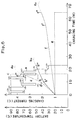
- Charging operation of the charging circuit 30 will be described in more detail with reference to a graph shown in FIG. 6.
- FIG. 6 also shows, as comparison, temperature rise in a case where a nickel metal hydride battery has been charged for one hour and temperature rise in a case where the battery is rapidly charged as well as the case of the battery charger in this embodiment.
- 1C charging is conducted as shown in dash line e of FIG. 6. That is, a 2AH nickel metal hydride battery is charged with 2A charging current for about one hour (65 minutes in FIG. 6).
- 1C charging charging starts at a temperature of 20°C as shown in dotted line f of FIG. 6 and ends at a temperature of 40°C. Due to the characteristics of the nickel metal hydride battery, a temperature rise is seen just before the completion of charging (55 minutes after the start of charging) shown in f' of FIG. 6 and further temperature rise is seen from a time f'' at which charging is completed (overshoot f0).
- the overshoot of the nickel metal hydride battery depends on the gradient of temperature rise at the time charging is completed. If a gradient at f'-f'' is small, overshoot-induced temperature rise is small. If the gradient is large, that is, temperature greatly increases at the end of charging, then overshoot-induced temperature rise is large.
- chain line c indicates current if a battery is rapidly charged (4.5C charging) with constant high current (9A) by a conventional battery charger so as to complete charging in approximately 20 minutes.
- Chain line d indicates the temperature change of the nickel metal hydride in rapid charging. As indicated by the chain line d, even if charging starts at a temperature of 20°C, the temperature reaches 70°C at which the nickel metal hydride battery life is shortened when charging is completed. Moreover, temperature rapidly rises just before the completion of charging (11 minutes after start) indicated by d' in FIG. 6 until d'' at which charging is completed. Due to this, temperature greatly rises at time d'' at which charging is completed (overshoot d0).
- the overshoot d0 causes temperature to rise further as high as 80°C even after charging is completed, as a result the life of the nickel metal hydride battery is shortened.
- a temperature rise is 60°C during that period. If, therefore, charging of the nickel metal hydride battery starts at 30°C, and temperature rises by 60°C to 90°C or higher, the battery performance greatly deteriorates at this point.
- Full line ⁇ a ⁇ indicates a change in charging current in the battery charger in the first embodiment according to the present invention
- full line ⁇ b ⁇ indicates a change in the temperature of nickel metal hydride battery if the battery is charged by the battery charger in this embodiment.
- the battery charger 10 in this embodiment applies relatively low charging current if battery temperature is high and temperature rise is large.
- the device 10 applies medium level charging current if battery temperature is high and temperature rise is small.
- the device 10 applies medium level charging current if battery temperature is low and temperature rise is large.
- the device 10 applies relatively high charging current if battery temperature is low and temperature rise is small.
- the battery charger 10 in this embodiment adjusts current based on the temperature of the nickel metal hydride battery and its temperature rise.
- the device 10 starts charging the battery at a temperature of 20°C as shown in the full line ⁇ b ⁇ while controlling the temperature to fall within 50°C or less so as not to affect the battery life. In other words, the device 10 adjusts charging current to maximum current while avoiding exceeding the expected temperature and shortening charging time.
- the battery charger 10 constantly changes charging current in accordance with the battery temperature and temperature rise. That is, high current is applied at an initial charging stage, i.e., while battery temperature is low and temperature rise is small. Relatively low charging current is applied at a final charging stage, i.e., if battery temperature is high and temperature rise is large so that temperature rise is kept small just before the completion of charging. Specifically, temperature rise is small (or temperature rise gradient is small) from a time b' (11 minutes after the start of charging) just before the completion of charging until a time b'' at which charging is completed.
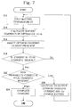
- a control section 36 of the battery charger adjusts charging current and determines whether battery charging is completed in a predetermined cycle (here, at 100 seconds' intervals for the convenience of description, but actually far shorter intervals of 10 seconds or less). Specifically, first, the absolute temperature T of the nickel metal hydride battery is inputted (in step S12). Next, the inputted absolute temperature T is differentiated and a battery temperature difference dT/dt is calculated (in step S14). Based on the absolute temperature T and the temperature difference dT/dt, an optimum charging current is selected from the map which has been already described with reference to FIG. 5 (in step S16).
- region I12 is selected and relatively high current of 4.5C charging current (9A) is applied as indicated by the full line a shown in FIG. 7.
- control section 36 determines whether current is in final charging regions, i.e., hatched regions I31, I32, I33, I34 and I35 in which temperature rise is large and in a region I25 in which temperature rise is medium level (in step S18). In this case, since the current is not in the final charging region ("NO" in the Step S18), process returns to the step S12 and control of the charging current continues.
- cycle ⁇ 2 ⁇ after more than 100 seconds pass, because a relatively high current has been applied in cycle ⁇ 1 ⁇ as stated above, the temperature difference dT/dt is larger (X1 to X2) and region I22 is selected, so that medium level current (3.5C) is selected. Since the medium level current is selected in the cycle ⁇ 2 ⁇ , the temperature difference dT/dt turns into X1 or less. In cycle ⁇ 3 ⁇ , the region I12 is selected and relatively high charging current is thereby selected once again.
- the difference dT/dt gradually increases.
- the temperature difference dT/dt exceeds X2 and enters region I33.
- the determination result is Yes in step 18. That is, current is determined in the final charging regions (regions I31, I32, I33, I34, I35 and I25) as stated above, and it is then determined whether current is highly probable in the final charging regions (in step S22). It is determined that it is highly probable in the final charging regions if it enters the final charging regions in three consecutive cycles.
- step S22 While the current is decreased in the cycle ⁇ 6 ⁇ , the absolute temperature T is between T2 and T3 and the temperature difference dT/dt is decreased to X1 to X2 in the next cycle ⁇ 7 ⁇ , whereby current is in the region I23.
- the determination result as to whether it is highly probable that current is in the final charging region is Low in step S22 and the process goes on to step 20 in which charging continues with a variable charging current.
- step S24 the determination result as to whether it is high probable that current enters a final charging region is High and charging is completed (in step S24), thereby ending all series of processing.
- cycle time is 100 seconds for convenience of description. Due to this, it is determined that it is highly probable if current enters final charging regions in three consecutive cycles. If cycle time is made shorter than a 100 seconds' cycle, it is possible to determine that it is high probable that current enters final charging regions using various methods. For instance, in a 10 seconds' cycle, it is highly probable that current enters the final charging regions in eight out of 10 cycles. Alternatively, it can be determined that probability is high if current enters the final charging regions in eight out of 10 cycles and if current enters the final charging regions in five consecutive cycles.
- the conventional battery charger for charging a nickel-cadmium battery detects that charging is completed by keeping a current value constant and monitoring one or more of temperature, temperature change, voltage and voltage change.
- patterns of temperature and voltage change vary in accordance with the battery remaining capacity, battery temperature at the start of battery charging and outside temperature. Due to this, it has been difficult to fully charge the nickel metal hydride battery without fear of overcharge.
- the battery charger in this embodiment by contrast, continuously monitors the absolute temperature T and temperature difference dT/dt while narrowing down charging current. It is, therefore, possible to fully charge the battery without fear of overcharge.
- the embodiment has been described so far, taking processing for charging a nickel metal hydride battery for an example.
- the battery charger and charging method according to the present invention can be also applied to processing for charging a nickel-cadmium battery.
- the map shown in FIG. 5 is adjusted to the characteristics of the nickel-cadmium battery, the present invention is applicable to the process for charging a nickel-cadmium battery.
- the map is adjusted to the common characteristics (greatest common divisor) of a nickel-cadmium battery and a nickel metal hydride battery, both the nickel-cadmium battery and the nickel metal hydride battery can be charged.
- the battery pack 50 may be provided with a discriminating terminal (such as a boss) for discriminating a nickel metal hydride battery from a nickel-cadmium battery and a map may be prepared for each of the nickel metal hydride battery and the nickel-cadmium battery at the battery charger side. If the battery pack 50 of the nickel metal hydride battery is installed, charging can be controlled according to the map for the nickel metal hydride battery. If the battery pack 50 of the nickel-cadmium is installed, charging can be controlled according to the map for the nickel-cadmium battery.
- the map is retrieved and the battery is charged with allowable current with which the battery can be charged while suppressing battery temperature from rising.
- This makes it possible to charge a nickel metal hydride battery, the temperature of which tends to rise during charging, for a short period of time without causing a deterioration in the battery due to temperature rise.
- the temperature rise of the nickel metal hydride battery is larger and the battery is charged with a relatively low current, so that it is possible to suppress "overshoot" after the completion of charging.
- the map is retrieved and the battery is charged with allowable current with which the battery can be charged while suppressing battery temperature from rising.
- This makes it possible to charge a nickel metal hydride battery, the temperature of which tends to rise during charging, for a short period of time without causing deterioration in the battery due to temperature rise.
- the temperature rise of the nickel metal hydride battery is larger and the battery is charged with relatively low current, so that it is possible to suppress "overshoot" after the completion of charging.
- the completion of charging is determined, in particular, based on whether or not temperature rise is large and whether or not temperature rise is large even if the charging current is lowered. Due to this, it is possible to fully charge the battery without fear of overcharge and without being influenced by the remaining battery capacity, temperature and the like.
Landscapes
- Engineering & Computer Science (AREA)
- Power Engineering (AREA)
- Charge And Discharge Circuits For Batteries Or The Like (AREA)
- Secondary Cells (AREA)
Applications Claiming Priority (2)
| Application Number | Priority Date | Filing Date | Title |
|---|---|---|---|
| JP06473698A JP3378189B2 (ja) | 1998-02-28 | 1998-02-28 | 充電装置及び充電方法 |
| JP6473698 | 1998-02-28 |
Publications (3)
| Publication Number | Publication Date |
|---|---|
| EP0939474A2 true EP0939474A2 (de) | 1999-09-01 |
| EP0939474A3 EP0939474A3 (de) | 2000-09-27 |
| EP0939474B1 EP0939474B1 (de) | 2008-08-13 |
Family
ID=13266741
Family Applications (1)
| Application Number | Title | Priority Date | Filing Date |
|---|---|---|---|
| EP99102765A Expired - Lifetime EP0939474B1 (de) | 1998-02-28 | 1999-02-23 | Batterielader und Ladeverfahren |
Country Status (4)
| Country | Link |
|---|---|
| US (4) | US6075347A (de) |
| EP (1) | EP0939474B1 (de) |
| JP (1) | JP3378189B2 (de) |
| DE (1) | DE69939288D1 (de) |
Cited By (7)
| Publication number | Priority date | Publication date | Assignee | Title |
|---|---|---|---|---|
| WO2002003525A1 (en) * | 2000-06-30 | 2002-01-10 | Matsushita Electric Industrial Co., Ltd. | Charger, battery pack, and charging system using the charger and battery pack |
| EP0982829A3 (de) * | 1998-07-03 | 2003-07-02 | Makita Corporation | Batterieladegerät |
| EP1100170A3 (de) * | 1999-11-10 | 2004-11-10 | Makita Corporation | Batterieladevorrichtung |
| EP1439624A3 (de) * | 2003-01-14 | 2005-01-19 | Makita Corporation | Batterieladegerät |
| WO2007110691A1 (en) * | 2006-03-27 | 2007-10-04 | Sony Ericsson Mobile Communications Ab | Battery charge temperature control |
| EP1848088A4 (de) * | 2005-01-18 | 2016-04-27 | Lenovo Innovations Ltd Hong Kong | Mobiles endgerät und batterieaufladeverfahren für das mobile endgerät |
| EP4138254A1 (de) * | 2021-08-20 | 2023-02-22 | Hilti Aktiengesellschaft | Verfahren zum schnellladen eines akkumulators |
Families Citing this family (53)
| Publication number | Priority date | Publication date | Assignee | Title |
|---|---|---|---|---|
| JP3378189B2 (ja) * | 1998-02-28 | 2003-02-17 | 株式会社マキタ | 充電装置及び充電方法 |
| US6476584B2 (en) | 1999-03-25 | 2002-11-05 | Makita Corporation | Battery charger and battery charging method |
| JP3495637B2 (ja) | 1999-03-26 | 2004-02-09 | 株式会社マキタ | 充電装置及び充電方式 |
| US6326767B1 (en) | 1999-03-30 | 2001-12-04 | Shoot The Moon Products Ii, Llc | Rechargeable battery pack charging system with redundant safety systems |
| JP3581064B2 (ja) | 1999-11-10 | 2004-10-27 | 株式会社マキタ | 充電装置 |
| US6806680B2 (en) | 2000-08-28 | 2004-10-19 | Milwaukee Electric Tool Corporation | Portable battery charger |
| JP2002165380A (ja) * | 2000-11-24 | 2002-06-07 | Tokyo R & D Co Ltd | 組電池の充電システム |
| JP2002313412A (ja) * | 2001-04-10 | 2002-10-25 | Matsushita Electric Ind Co Ltd | 二次電池の活性化方法 |
| US6753671B1 (en) | 2001-04-17 | 2004-06-22 | Thomas Patrick Harvey | Recharger for use with a portable electronic device and which includes a proximally located light emitting device |
| US6762584B2 (en) | 2001-04-17 | 2004-07-13 | Thomas Patrick Harvey | Recharger for use with a portable electronic device and which includes a connector terminus for communicating directly with rechargeable batteries contained within the device |
| JP3783576B2 (ja) * | 2001-05-25 | 2006-06-07 | 日立工機株式会社 | 充電機能付き直流電源装置 |
| JP3805664B2 (ja) | 2001-11-01 | 2006-08-02 | 株式会社マキタ | 電池パック |
| US6661203B2 (en) * | 2001-11-12 | 2003-12-09 | Hewlett-Packard Development Company, L.P. | Battery charging and discharging system optimized for high temperature environments |
| US6949914B2 (en) * | 2002-10-11 | 2005-09-27 | Hitachi Koki Co., Ltd. | Charging apparatus |
| JP3936286B2 (ja) * | 2002-12-24 | 2007-06-27 | 株式会社マキタ | 充電装置及び充電方法 |
| US20040145352A1 (en) * | 2003-01-07 | 2004-07-29 | Chris Harrison | Method and apparatus for providing temperature-regulated battery charging |
| US20060113956A1 (en) * | 2003-05-07 | 2006-06-01 | Bublitz Scott D | Battery charger and assembly |
| DE10327005B4 (de) * | 2003-06-12 | 2007-01-18 | Ernst U. Willy Niegeloh Gmbh & Co. Kg | Hornhauthobel |
| JP4085906B2 (ja) * | 2003-07-18 | 2008-05-14 | 日立工機株式会社 | 電池の充電装置 |
| US7701172B2 (en) * | 2003-10-14 | 2010-04-20 | Black & Decker Inc. | Power driver and charger with flexible mounting system for battery pack |
| FR2862558B1 (fr) * | 2003-11-20 | 2006-04-28 | Pellenc Sa | Outil portatif electrique autonome de puissance |
| US7158999B2 (en) * | 2004-02-20 | 2007-01-02 | Mainstar Software Corporation | Reorganization and repair of an ICF catalog while open and in-use in a digital data storage system |
| RU2269843C1 (ru) * | 2004-05-21 | 2006-02-10 | Военно-космическая академия им. А.Ф. Можайского | Способ заряда аккумуляторной батареи и устройство для его осуществления |
| US20050275378A1 (en) * | 2004-06-14 | 2005-12-15 | Serafino Canino | Apparatus and method for illuminated battery charging device |
| CN2762964Y (zh) * | 2005-01-10 | 2006-03-08 | 南京德朔实业有限公司 | 用电池供电的电动工具 |
| US7880445B2 (en) * | 2006-02-16 | 2011-02-01 | Summit Microelectronics, Inc. | System and method of charging a battery using a switching regulator |
| US7528574B1 (en) | 2006-02-16 | 2009-05-05 | Summit Microelectronics, Inc. | Systems and methods of programming voltage and current in a battery charger |
| US7834591B2 (en) * | 2006-02-16 | 2010-11-16 | Summit Microelectronics, Inc. | Switching battery charging systems and methods |
| US8120328B2 (en) * | 2006-03-24 | 2012-02-21 | Nec Corporation | Charging system, charging control program, and portable terminal |
| US7615969B2 (en) | 2006-07-27 | 2009-11-10 | Dell Products L.P. | Systems and methods for temperature-dependent battery charging |
| JP2008218210A (ja) | 2007-03-05 | 2008-09-18 | Lenovo Singapore Pte Ltd | 電池パックおよび携帯式電子機器 |
| JP4660523B2 (ja) * | 2007-09-19 | 2011-03-30 | レノボ・シンガポール・プライベート・リミテッド | 電池セルの表面温度で充電制御する充電システム |
| US20100190052A1 (en) * | 2009-01-27 | 2010-07-29 | Umesh Rajani | Battery pack with high and low current discharge terminals |
| JP4635094B2 (ja) * | 2009-04-30 | 2011-02-16 | 株式会社東芝 | 情報処理装置 |
| JP4966998B2 (ja) * | 2009-06-18 | 2012-07-04 | パナソニック株式会社 | 充電制御回路、電池パック、及び充電システム |
| US20110187377A1 (en) * | 2010-02-03 | 2011-08-04 | Dale Boysen | Battery Charger Tester With Individual Cell Temperature Measurement |
| JP2011200101A (ja) * | 2010-02-25 | 2011-10-06 | Sanyo Electric Co Ltd | 蓄電システム |
| JP5477778B2 (ja) * | 2010-05-28 | 2014-04-23 | スズキ株式会社 | 電池並列接続回路の制御装置 |
| TWM402554U (en) * | 2010-11-10 | 2011-04-21 | Richtek Technology Corp | Charger circuit |
| KR101288122B1 (ko) * | 2011-01-03 | 2013-07-18 | 삼성에스디아이 주식회사 | 배터리 충전방법, 및 이를 적용한 배터리 팩 |
| US8633673B2 (en) * | 2011-03-28 | 2014-01-21 | Lenovo (Singapore) Pte. Ltd. | Battery charging system for notebook computer |
| JP2013074785A (ja) * | 2011-09-26 | 2013-04-22 | Hyundai Motor Co Ltd | 車両のバッテリー充電制御方法およびその装置 |
| US9197096B2 (en) * | 2012-01-19 | 2015-11-24 | Apple Inc. | Charging techniques for solid-state batteries in portable electronic devices |
| JP5655838B2 (ja) * | 2012-10-25 | 2015-01-21 | トヨタ自動車株式会社 | 電池システム |
| TWI512647B (zh) * | 2014-09-10 | 2015-12-11 | Ind Tech Res Inst | 電池充電方法 |
| DE102014220515B4 (de) * | 2014-10-09 | 2023-02-02 | Ford Global Technologies, Llc | Verfahren zur Überwachung des Zustands einer Batterie in einem Kraftfahrzeug |
| US10099562B2 (en) | 2014-10-15 | 2018-10-16 | Johnson Controls Technology Company | Cooling strategy for battery systems |
| US10418826B2 (en) * | 2015-11-30 | 2019-09-17 | Makita Corporation | Battery device and charging device |
| WO2019039114A1 (ja) * | 2017-08-23 | 2019-02-28 | ソニー株式会社 | 蓄電制御装置、蓄電制御方法及び蓄電システム |
| CN112204843A (zh) | 2018-05-30 | 2021-01-08 | 米沃奇电动工具公司 | 快速充电电池组 |
| US20220021036A1 (en) * | 2020-07-20 | 2022-01-20 | Milwaukee Electric Tool Corporation | Systems, methods, and devices for increased charging speed of lithium-based battery packs |
| US12015290B2 (en) | 2020-10-30 | 2024-06-18 | Techtronic Cordless Gp | Battery pack with temperature limited current |
| US12487648B2 (en) * | 2022-03-10 | 2025-12-02 | Microsoft Technology Licensing, Llc | Adaptive power control for an electronic device |
Family Cites Families (47)
| Publication number | Priority date | Publication date | Assignee | Title |
|---|---|---|---|---|
| US3917990A (en) * | 1974-04-11 | 1975-11-04 | Gen Electric | Battery charging control using temperature differential circuit |
| US5493199A (en) * | 1982-06-07 | 1996-02-20 | Norand Corporation | Fast battery charger |
| CA2022802A1 (en) * | 1989-12-05 | 1991-06-06 | Steven E. Koenck | Fast battery charging system and method |
| US5391974A (en) * | 1990-10-15 | 1995-02-21 | Toshiba Battery Co., Ltd. | Secondary battery charging circuit |
| US5563496A (en) * | 1990-12-11 | 1996-10-08 | Span, Inc. | Battery monitoring and charging control unit |
| EP0539640A1 (de) * | 1991-10-30 | 1993-05-05 | Texas Instruments Limited | Batterieverbesserungen |
| DE4200693C1 (de) * | 1992-01-14 | 1993-05-06 | Robert Bosch Gmbh, 7000 Stuttgart, De | |
| JPH05244729A (ja) * | 1992-01-24 | 1993-09-21 | Sanyo Electric Co Ltd | 電池の充電方法 |
| DE69222642T2 (de) * | 1992-03-16 | 1998-04-23 | Zip Charge Co | Schnell-lader und schnell-lademethode für nickel kadmium batterie |
| JP2599333B2 (ja) | 1992-10-07 | 1997-04-09 | 株式会社タムラ製作所 | 二次電池の充電方法 |
| CN1119054A (zh) * | 1993-03-05 | 1996-03-20 | 摩托罗拉公司 | 具有存储器的存储充电过程的电池 |
| BR9406038A (pt) | 1993-04-05 | 1995-12-12 | Black & Decker Inc | Pacote de bateria para dispositivo sem fio de conexão |
| JPH06315233A (ja) | 1993-04-28 | 1994-11-08 | Fujitsu Ltd | 電池の充電制御方法 |
| DE69409863T2 (de) * | 1993-05-05 | 1998-10-08 | Sgs Thomson Microelectronics | Batterieladegerät |
| JPH07105597A (ja) | 1993-10-05 | 1995-04-21 | Matsushita Electric Ind Co Ltd | 磁気記録装置の記録再生方法及びトラッキング方法 |
| JP2732204B2 (ja) * | 1993-09-29 | 1998-03-25 | 株式会社ジップチャージ | 二次電池の高速充電方法及びその装置 |
| US5519303A (en) * | 1993-09-30 | 1996-05-21 | Motorola, Inc. | Fast battery charging method and apparatus with temperature gradient detection |
| US5550453A (en) * | 1994-01-24 | 1996-08-27 | Motorola, Inc. | Battery charging method and apparatus |
| US5642031A (en) | 1994-02-28 | 1997-06-24 | Black & Decker Inc. | Battery recharging system with state of charge detection that initially detects whether a battery to be charged is already at or near full charge to prevent overcharging |
| US5548201A (en) * | 1994-09-13 | 1996-08-20 | Norand Corporation | Battery charging method and apparatus with thermal mass equalization |
| JP3157686B2 (ja) * | 1994-11-08 | 2001-04-16 | 松下電器産業株式会社 | 組電池の充電制御装置 |
| US5686808A (en) * | 1995-05-31 | 1997-11-11 | Lutz; Frank T. | Universal battery charger and method |
| FR2739724B1 (fr) * | 1995-10-05 | 1997-11-14 | Accumulateurs Fixes | Procede de charge de batteries nickel-cadmium etanches |
| TW348325B (en) * | 1996-01-26 | 1998-12-21 | Yamaha Motor Co Ltd | Method and apparatus for monitoring deterioration of a storage battery |
| US5668461A (en) * | 1996-02-13 | 1997-09-16 | Reserve Battery Cell, L.P. | Reserve battery having temperture compensation |
| FR2745433B1 (fr) * | 1996-02-27 | 1998-04-03 | Sgs Thomson Microelectronics | Dispositif de commande de la charge d'au moins une batterie |
| JPH09266639A (ja) | 1996-03-27 | 1997-10-07 | Makita Corp | 充電装置 |
| JPH1014125A (ja) * | 1996-06-25 | 1998-01-16 | Matsushita Electric Ind Co Ltd | ニッケルカドミウム2次電池またはニッケル水素2次電池の充電方法及びその装置 |
| JPH10150727A (ja) | 1996-11-18 | 1998-06-02 | Makita Corp | 充電装置 |
| WO1998040925A1 (en) * | 1997-03-12 | 1998-09-17 | Us Nanocorp. | A method for determining state-of-charge using an intelligent system |
| US6008628A (en) | 1997-08-20 | 1999-12-28 | Black & Decker Inc. | Method for charging batteries |
| US5825159A (en) * | 1997-09-29 | 1998-10-20 | Motorola, Inc. | Battery charging method for properly terminating rapid charge |
| US6018231A (en) | 1997-10-02 | 2000-01-25 | Black & Decker Inc. | Battery charging system |
| JP3378189B2 (ja) * | 1998-02-28 | 2003-02-17 | 株式会社マキタ | 充電装置及び充電方法 |
| JPH11266543A (ja) | 1998-03-18 | 1999-09-28 | Makita Corp | 電動工具充電システム |
| US5896024A (en) | 1998-03-24 | 1999-04-20 | Black & Decker, Inc. | Method and apparatus for manually selecting battery charging process |
| EP0964497B1 (de) * | 1998-06-09 | 2010-10-13 | Makita Corporation | Batterieladegerät |
| US5945803A (en) | 1998-06-09 | 1999-08-31 | Black & Decker Inc. | Apparatus for determining battery pack temperature and identity |
| US6172487B1 (en) | 1998-06-17 | 2001-01-09 | Black & Decker Inc. | Method and apparatus for charging batteries |
| US6175211B1 (en) | 1999-04-15 | 2001-01-16 | Black & Decker Inc. | Battery pack with identification device |
| JP3506916B2 (ja) * | 1998-07-03 | 2004-03-15 | 株式会社マキタ | 充電装置 |
| CA2276821C (en) | 1998-07-09 | 2007-11-27 | Daniele C. Brotto | Method for charging batteries |
| JP3495636B2 (ja) * | 1999-03-25 | 2004-02-09 | 株式会社マキタ | 充電装置 |
| JP3495637B2 (ja) * | 1999-03-26 | 2004-02-09 | 株式会社マキタ | 充電装置及び充電方式 |
| US6160389A (en) | 1999-08-27 | 2000-12-12 | Black & Decker Inc. | Battery charger with low heat dissipation |
| JP3638483B2 (ja) | 1999-11-10 | 2005-04-13 | 株式会社マキタ | 充電装置及び充電方式 |
| EP1100172A3 (de) | 1999-11-10 | 2004-10-13 | Makita Corporation | Batterieladevorrichtung |
-
1998
- 1998-02-28 JP JP06473698A patent/JP3378189B2/ja not_active Expired - Fee Related
-
1999
- 1999-02-23 EP EP99102765A patent/EP0939474B1/de not_active Expired - Lifetime
- 1999-02-23 DE DE69939288T patent/DE69939288D1/de not_active Expired - Lifetime
- 1999-02-26 US US09/258,140 patent/US6075347A/en not_active Expired - Lifetime
-
2000
- 2000-03-20 US US09/531,596 patent/US6204641B1/en not_active Expired - Lifetime
-
2001
- 2001-02-13 US US09/781,318 patent/US6433517B2/en not_active Expired - Fee Related
-
2002
- 2002-07-22 US US10/201,709 patent/US6603288B2/en not_active Expired - Lifetime
Cited By (11)
| Publication number | Priority date | Publication date | Assignee | Title |
|---|---|---|---|---|
| EP0982829A3 (de) * | 1998-07-03 | 2003-07-02 | Makita Corporation | Batterieladegerät |
| EP1100170A3 (de) * | 1999-11-10 | 2004-11-10 | Makita Corporation | Batterieladevorrichtung |
| WO2002003525A1 (en) * | 2000-06-30 | 2002-01-10 | Matsushita Electric Industrial Co., Ltd. | Charger, battery pack, and charging system using the charger and battery pack |
| US6777915B2 (en) | 2000-06-30 | 2004-08-17 | Matsushita Electric Industrial Co., Ltd. | Charger, battery pack, and charging system using the charger and battery pack |
| EP1439624A3 (de) * | 2003-01-14 | 2005-01-19 | Makita Corporation | Batterieladegerät |
| EP1848088A4 (de) * | 2005-01-18 | 2016-04-27 | Lenovo Innovations Ltd Hong Kong | Mobiles endgerät und batterieaufladeverfahren für das mobile endgerät |
| WO2007110691A1 (en) * | 2006-03-27 | 2007-10-04 | Sony Ericsson Mobile Communications Ab | Battery charge temperature control |
| US7521897B2 (en) | 2006-03-27 | 2009-04-21 | Sony Ericsson Mobile Communications Ab | Battery charge temperature control |
| EP4138254A1 (de) * | 2021-08-20 | 2023-02-22 | Hilti Aktiengesellschaft | Verfahren zum schnellladen eines akkumulators |
| WO2023020849A1 (de) * | 2021-08-20 | 2023-02-23 | Hilti Aktiengesellschaft | Verfahren zum schnellladen eines akkumulators |
| CN117652071A (zh) * | 2021-08-20 | 2024-03-05 | 喜利得股份公司 | 用于为可充电电池快速充电的方法 |
Also Published As
| Publication number | Publication date |
|---|---|
| US6204641B1 (en) | 2001-03-20 |
| EP0939474A3 (de) | 2000-09-27 |
| DE69939288D1 (de) | 2008-09-25 |
| US20020175659A1 (en) | 2002-11-28 |
| US6433517B2 (en) | 2002-08-13 |
| US6603288B2 (en) | 2003-08-05 |
| US6075347A (en) | 2000-06-13 |
| JP3378189B2 (ja) | 2003-02-17 |
| US20010009362A1 (en) | 2001-07-26 |
| JPH11252814A (ja) | 1999-09-17 |
| EP0939474B1 (de) | 2008-08-13 |
Similar Documents
| Publication | Publication Date | Title |
|---|---|---|
| US6075347A (en) | Battery charger and charging method | |
| US6191560B1 (en) | Battery charger | |
| JP3495637B2 (ja) | 充電装置及び充電方式 | |
| JP3936286B2 (ja) | 充電装置及び充電方法 | |
| US6476584B2 (en) | Battery charger and battery charging method | |
| US6172487B1 (en) | Method and apparatus for charging batteries | |
| US6225786B1 (en) | Battery charger | |
| JP3638483B2 (ja) | 充電装置及び充電方式 | |
| WO1994026014A1 (en) | Method and apparatus for charging a battery | |
| EP1261098A2 (de) | Verfahren und Vorrichtung zur Batterieladung | |
| JP3390668B2 (ja) | 充電装置 | |
| JP3390666B2 (ja) | 充電装置 | |
| US6249107B1 (en) | Method of charging a battery in a mobile charger | |
| JP3390667B2 (ja) | 充電装置 | |
| JP3707636B2 (ja) | 充電制御方法および充電制御装置 | |
| JPH08149709A (ja) | 二次電池の充電装置 | |
| JPH1174001A (ja) | 鉛蓄電池の充電方法 | |
| JP2928439B2 (ja) | 二次電池の充電検出方法及び装置 | |
| JPH06339234A (ja) | 充電制御装置 | |
| KR100620871B1 (ko) | 소형 충전밧데리용 충전기의 충전방법 | |
| JP2002112467A (ja) | 充電装置 | |
| KR20070012108A (ko) | 소형 충전밧데리용 충전기의 충전방법 | |
| JPH07240234A (ja) | 二次電池の充電方法 |
Legal Events
| Date | Code | Title | Description |
|---|---|---|---|
| PUAI | Public reference made under article 153(3) epc to a published international application that has entered the european phase |
Free format text: ORIGINAL CODE: 0009012 |
|
| AK | Designated contracting states |
Kind code of ref document: A2 Designated state(s): DE FR GB |
|
| AX | Request for extension of the european patent |
Free format text: AL;LT;LV;MK;RO;SI |
|
| PUAL | Search report despatched |
Free format text: ORIGINAL CODE: 0009013 |
|
| RIC1 | Information provided on ipc code assigned before grant |
Free format text: 7H 02J 7/10 A, 7H 02J 7/00 B |
|
| AK | Designated contracting states |
Kind code of ref document: A3 Designated state(s): AT BE CH CY DE DK ES FI FR GB GR IE IT LI LU MC NL PT SE |
|
| AX | Request for extension of the european patent |
Free format text: AL;LT;LV;MK;RO;SI |
|
| 17P | Request for examination filed |
Effective date: 20000906 |
|
| AKX | Designation fees paid |
Free format text: DE FR GB |
|
| GRAP | Despatch of communication of intention to grant a patent |
Free format text: ORIGINAL CODE: EPIDOSNIGR1 |
|
| GRAS | Grant fee paid |
Free format text: ORIGINAL CODE: EPIDOSNIGR3 |
|
| GRAA | (expected) grant |
Free format text: ORIGINAL CODE: 0009210 |
|
| AK | Designated contracting states |
Kind code of ref document: B1 Designated state(s): DE FR GB |
|
| REG | Reference to a national code |
Ref country code: GB Ref legal event code: FG4D |
|
| REF | Corresponds to: |
Ref document number: 69939288 Country of ref document: DE Date of ref document: 20080925 Kind code of ref document: P |
|
| PLBE | No opposition filed within time limit |
Free format text: ORIGINAL CODE: 0009261 |
|
| STAA | Information on the status of an ep patent application or granted ep patent |
Free format text: STATUS: NO OPPOSITION FILED WITHIN TIME LIMIT |
|
| 26N | No opposition filed |
Effective date: 20090514 |
|
| PGFP | Annual fee paid to national office [announced via postgrant information from national office to epo] |
Ref country code: FR Payment date: 20130301 Year of fee payment: 15 Ref country code: DE Payment date: 20130220 Year of fee payment: 15 Ref country code: GB Payment date: 20130220 Year of fee payment: 15 |
|
| REG | Reference to a national code |
Ref country code: DE Ref legal event code: R119 Ref document number: 69939288 Country of ref document: DE |
|
| GBPC | Gb: european patent ceased through non-payment of renewal fee |
Effective date: 20140223 |
|
| REG | Reference to a national code |
Ref country code: FR Ref legal event code: ST Effective date: 20141031 |
|
| REG | Reference to a national code |
Ref country code: DE Ref legal event code: R119 Ref document number: 69939288 Country of ref document: DE Effective date: 20140902 |
|
| PG25 | Lapsed in a contracting state [announced via postgrant information from national office to epo] |
Ref country code: FR Free format text: LAPSE BECAUSE OF NON-PAYMENT OF DUE FEES Effective date: 20140228 Ref country code: DE Free format text: LAPSE BECAUSE OF NON-PAYMENT OF DUE FEES Effective date: 20140902 Ref country code: GB Free format text: LAPSE BECAUSE OF NON-PAYMENT OF DUE FEES Effective date: 20140223 |