EP0938857B1 - Geneigte Gleitvorrichtung für vertikale Schubladen - Google Patents
Geneigte Gleitvorrichtung für vertikale Schubladen Download PDFInfo
- Publication number
- EP0938857B1 EP0938857B1 EP98119151A EP98119151A EP0938857B1 EP 0938857 B1 EP0938857 B1 EP 0938857B1 EP 98119151 A EP98119151 A EP 98119151A EP 98119151 A EP98119151 A EP 98119151A EP 0938857 B1 EP0938857 B1 EP 0938857B1
- Authority
- EP
- European Patent Office
- Prior art keywords
- drawer
- slide
- support surfaces
- frame
- support
- Prior art date
- Legal status (The legal status is an assumption and is not a legal conclusion. Google has not performed a legal analysis and makes no representation as to the accuracy of the status listed.)
- Expired - Lifetime
Links
- 230000000712 assembly Effects 0.000 title claims description 23
- 238000000429 assembly Methods 0.000 title claims description 23
- 230000007246 mechanism Effects 0.000 claims 3
- 238000010276 construction Methods 0.000 description 5
- 210000000038 chest Anatomy 0.000 description 3
- 238000012986 modification Methods 0.000 description 3
- 230000004048 modification Effects 0.000 description 3
- 238000011161 development Methods 0.000 description 1
- 230000018109 developmental process Effects 0.000 description 1
- 239000002783 friction material Substances 0.000 description 1
- 238000007689 inspection Methods 0.000 description 1
- 238000003466 welding Methods 0.000 description 1
Images
Classifications
-
- B—PERFORMING OPERATIONS; TRANSPORTING
- B25—HAND TOOLS; PORTABLE POWER-DRIVEN TOOLS; MANIPULATORS
- B25H—WORKSHOP EQUIPMENT, e.g. FOR MARKING-OUT WORK; STORAGE MEANS FOR WORKSHOPS
- B25H3/00—Storage means or arrangements for workshops facilitating access to, or handling of, work tools or instruments
- B25H3/02—Boxes
- B25H3/021—Boxes comprising a number of connected storage elements
- B25H3/023—Boxes comprising a number of connected storage elements movable relative to one another for access to their interiors
- B25H3/028—Boxes comprising a number of connected storage elements movable relative to one another for access to their interiors by sliding extraction from within a common frame
-
- A—HUMAN NECESSITIES
- A47—FURNITURE; DOMESTIC ARTICLES OR APPLIANCES; COFFEE MILLS; SPICE MILLS; SUCTION CLEANERS IN GENERAL
- A47B—TABLES; DESKS; OFFICE FURNITURE; CABINETS; DRAWERS; GENERAL DETAILS OF FURNITURE
- A47B88/00—Drawers for tables, cabinets or like furniture; Guides for drawers
- A47B88/40—Sliding drawers; Slides or guides therefor
- A47B88/42—Vertically-oriented drawers, i.e. drawers where the height exceeds the width
-
- A—HUMAN NECESSITIES
- A47—FURNITURE; DOMESTIC ARTICLES OR APPLIANCES; COFFEE MILLS; SPICE MILLS; SUCTION CLEANERS IN GENERAL
- A47B—TABLES; DESKS; OFFICE FURNITURE; CABINETS; DRAWERS; GENERAL DETAILS OF FURNITURE
- A47B88/00—Drawers for tables, cabinets or like furniture; Guides for drawers
- A47B88/40—Sliding drawers; Slides or guides therefor
- A47B88/42—Vertically-oriented drawers, i.e. drawers where the height exceeds the width
- A47B2088/421—Vertically-oriented drawers, i.e. drawers where the height exceeds the width the bottom, cabinet side slide having a U-shape section opening upwards
Definitions
- the present invention relates to storage cabinets for articles such as tools and, in particular, to vertically-oriented drawers or like storage units for such cabinets.
- Typical tool chests or cabinets are provided with horizontally arranged shelves, drawers, trays and the like for containing or supporting tools or other items. Since horizontal drawers can sometimes make it difficult for the user, such as an automotive mechanic or the like, to readily see or gain access to the contents of a drawer, tool cabinets or storage devices have also been provided with upstanding support panels or pallets or the like on which tools can be clipped or hung for better display to the user.
- Such upright arrangements may, for example, include wall cabinets, with a tool-support wall arranged vertically in use, and tool chests with pop-up tool pallets, which can be raised from a horizontal position to an upstanding position for better display and access.
- wall cabinets and tool chests with pop-up pallets have only a single pallet or tool-support wall.
- drawer slide assemblies which commonly include two or three interfitted slide members or rails slidably movable relative to each other, usually with the aid of a friction-reducing arrangement, such as the use of low-friction materials, ball races and the like.
- the rails or tracks of these drawer slide assemblies are commonly channel-shaped, having a width substantially greater than the depth, the assemblies typically being mounted with the channel width oriented vertically in use.
- the drawer slide assembly has uneven rigidity in horizontal and vertical directions.
- US-A-3057672 discloses a cabinet mounting system including a vertical, upstanding drawer. Two diagonally opposed slide assemblies are provided for connecting the drawer to a housing.
- US-A-1111026 discloses a drawer guide comprising a slide assembly having a plurality of balls slideably disposed within a channelway having longitudinally disposed elongated apertures, thereby defining an arc of the surfaces of the balls to be in slideable, abutting, non-connecting relationship with an outer surface of the drawer.
- the outer surface of the drawer slideably engages the balls, thereby providing slideable movement of the drawer relative to the slide assembly.
- An important feature of the invention is the provision of a drawer and slide combination which has improved rigidity in the open position.
- another feature of the invention is the provision of a combination of the type set forth, which is particularly adapted for use with vertically-arranged drawers.
- Another feature of the invention is the provision of a combination of the type set forth, which includes drawer slide assemblies of the type utilizing elongated, relatively slidable tracks or rails.
- Still another feature of the invention is the provision of a tool cabinet incorporating drawer and slide combinations of the type set forth.
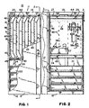
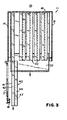
- FIGS. 1-3 there is illustrated a tool cabinet, generally designated by the numeral 10, constructed in accordance with and embodying the features of the present invention.
- the tool cabinet 10 has a generally box-like, upstanding housing 11 including a bottom wall 12, a top wall 13, opposed side walls 14 and 15, and a rear wall 16, being closed by a front door 17 provide with a lock 18.
- the tool cabinet 10 includes a lower storage compartment 20, defined generally between a horizontal shelf 21 and the bottom wall 12.
- a plurality of vertically-spaced horizontal drawers 22 are disposed in the lower storage compartment 20 and are mounted for sliding movement on standard ball slide assemblies (not shown) for movement between a closed position, illustrated in FIGS. 1 and 2, disposed entirely within the lower storage compartment 20, and an open position extending from the storage compartment 20, as indicated in FIG. 3.
- the drawers 20 are opened by moving in the direction of the arrows in FIGS. 2 and 3.
- the tool cabinet 10 also has an upper storage compartment 23 and a framework including a lower frame member 24 mounted above the shelf 21 and an upper frame member 27 mounted beneath the top wall 13, which frame members respectively define the lower and upper ends of the upper storage compartment 23.
- the lower frame member 24 has a generally horizontally disposed base wall 25 with upstanding attachment flanges 26 for attachment, respectively, to the housing side walls 14 and 15, while the upper frame member 27 has a base wall 28 and attachment flanges 29.
- Mounted on the upper frame member 27 at laterally spaced-apart locations thereon are a plurality of upper drawer slide supports 30, while a like plurality of lower drawer slide supports 35 are mounted on the lower frame member 24.
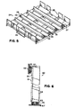
- the assembly of the upper frame member 27 an upper drawer slide supports 30 is arranged as a mirror image of the assembly of the lower frame member 24 and lower drawer slide supports 35, the lower assembly being illustrated in FIG. 5.
- Each of the upper drawer slide supports 30 is an elongated member extending the entire front-to-back depth of the upper storage compartment 23 and includes a vertical wall 31 integral with an inclined wall 32, the walls 31 and 32 being respectively provided at their distal ends with attachment flanges 33 and 34 which are, respectively, fixedly secured to the upper frame member 27, as by welding.
- each of the lower drawer slide supports 35 has a vertical wall 36, an inclined wall 37 and attachment flanges 38 and 39 which are, respectively, fixed to the base wall 25 of the lower frame member 24.
- the upper drawer slide supports 30 are, respectively, vertically aligned with the lower drawer slide supports 35 to form vertically spaced pairs, so that in each pair the vertical walls 31 and 36 are substantially coplanar, and the inclined walls 32 and 37 respectively lie in intersecting planes.
- the inclined walls 32 and 37 respectively intersect the vertical walls 31 and 36 at an angle of about 30°. However, other angles, such as 45°, could also be used.
- the drawers 40 are of identical construction, each having a vertical wall 41 arranged parallel to the cabinet side walls 14 and 15 and integral at its upper and lower ends with upper and lower inclined walls 42 and 43, which respectively slope upwardly and downwardly in the same lateral direction, so as to be respectively substantially parallel to the inclined walls 32 an 37 of the associated drawer slide supports 30, 35.
- the inclined walls 42 and 43 are respectively integral at their distal ends with top and bottom walls 44 an 45, all of the walls 41-45 being provided at their front and rear ends with attachment flanges to facilitate attachment to end walls 46.
- a tool support panel 47 mounted within the drawer 40 between the inclined walls 42 and 43 and parallel to the vertical wall 41 is a tool support panel 47, which is perforated with a plurality of substantially uniformly spaced holes 48 and vertically elongated slots 49.
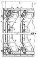
- each drawer slide assembly 50 is preferably a ball slide assembly of known construction, having three slide members, including a frame slide member 51 fixed to the inclined wall 32 or 37 of the associated drawer slide support 30 or 35, a drawer slide member 52 fixed to the associated inclined wall 42 or 43 of the drawer 40, and an intermediate slide member 53.
- a ball race 54 is interposed between the frame slide member 51 and the intermediate slide member 53, while a ball race 55 is interposed between the intermediate slide member 53 and the drawer slide member 52, as illustrated in FIG. 4, all in a known manner.
- each drawer slide assembly 50 has an axis plane X which is substantially parallel to the inclined walls 32, 42 or 37, 43 of the associated drawer slide support 30, 35 and drawer 50.
- the drawer 40 can be slid from its closed position to its open position in the direction of the arrows in FIGS. 2 and 3 to provide access thereto by the user.
- the inclined arrangement of the drawer slide assemblies 50 provides improved rigidity for each drawer 40 in its open position, resisting deflecting forces in both vertical and horizontal directions. In the illustrated embodiment the arrangement will have a slightly greater resistance to horizontal force components than to vertical force components. If, on the other hand, the inclined walls 32, 37 and 42, 43 were inclined at 45° angles, they would have substantially equal resistance to both horizontal and vertical force components.
- tools can be hung or clipped onto the drawer tool support panels 47 by any known means.
- separate tool holders 56 or 57 could be hung on the tool support panel 47 by the use of suitable hooks, clips or the like, for respectively supporting pluralities of tools, such as screwdrivers 58 or cans or other containers 58a.
- tools such as a hammer 58b (FIG. 2) or other type of tool 58c or 58d (FIGS. 2 and 4) may be individually mounted by the use of hooks 59, in a known manner.
- FIG. 6 there is illustrated an alternative arrangement for mounting a vertical drawer 60 having a vertical rear wall 61, horizontal top an bottom walls 62 and 63 and vertical end walls 64, supporting therein a vertically-arranged tool support panel 65.
- the drawer 60 is supported at its upper and lower ends by two drawer slide assemblies 70, which may be identical to the drawer slide assemblies 50, described above.
- the upper drawer slide assembly 70 is mounted between the vertical wall 61 of the drawer 60 and an adjacent vertical support member 66, which may depend from the upper frame member 27, while the lower drawer slide assembly 70 is interposed between the bottom wall 63 of the drawer 60 and a horizontal support member 67, which may be the lower frame member 24, or a member mounted thereon.
- the drawer slide assemblies 70 are respectively arranged in vertical and horizontal planes so that, in combination, they will still resist deflecting forces in both horizontal and vertical directions.
Landscapes
- Engineering & Computer Science (AREA)
- Mechanical Engineering (AREA)
- Drawers Of Furniture (AREA)
- Combinations Of Kitchen Furniture (AREA)
Claims (20)
- Schublade mit Gleitvorrichtung hierfür mit
einem Rahmen (24, 27), der eine obere und untere vertikal ausgerichtete, nichtparallele Lagerfläche (32, 37) aufweist,
einer aufrecht angeordneten Schublade (40) mit einem oberen und einem unteren Ende, die benachbart zur oberen und unteren Lagerfläche (32, 37) angeordnet sind,
einem oberen Gleitmechanismus (50), der das obere Ende der Schublade (40) mit der oberen Lagerfläche (32) zur Durchführung einer relativen Gleitbewegung parallel zur oberen Lagerfläche verbindet, und
einem unteren Gleitmechanismus (50), der das untere Ende der Schublade (40) mit der unteren Lagerfläche (37) zur Durchführung einer relativen Gleitbewegung parallel zur unteren Lagerfläche verbindet. - Schublade nach Anspruch 1, bei der die obere und untere Lagerfläche in Ebenen liegen, die im wesentlichen senkrecht zueinander verlaufen.
- Schublade nach Anspruch 2, bei der eine der Ebenen im Gebrauch im wesentlichen vertikal angeordnet ist.
- Schublade nach Anspruch 1, bei der jede der oberen und unteren Lagerflächen (32, 37) im Gebrauch relativ zur Vertikalen und zur Horizontalen geneigt ist.
- Schublade nach Anspruch 4, bei der jede der oberen und unteren Lagerflächen (32, 37) im Gebrauch unter einem Winkel von etwa 30° zur Vertikalen geneigt ist.
- Schublade nach Anspruch 1, bei der das obere und untere Ende der Schublade (40) eine obere und untere Montagefläche (42, 43) besitzen, die parallel zur oberen und unteren Lagerfläche (32, 37) verlaufen.
- Schublade nach Anspruch 1, bei der jeder des oberen und unteren Gleitmechanismus (50) eine mehrteilige Schubladengleiteinheit aufweist.
- Schublade nach Anspruch 1, die ein aufrecht angeordnetes perforiertes Lagerpaneel (47) aufweist, an dem zugehörige Gegenstände aufgehangen werden können.
- Schublade mit Gleitvorrichtung hierfür mit
einem Rahmen (24, 27), der eine erste und zweite vertikal ausgerichtete, nichtparallele Rahmenlagerfläche (32, 37) aufweist,
einer Schublade (40) mit einer ersten und zweiten Schubladenlagerfläche (42, 43), die sich parallel zur ersten und zweiten Rahmenlagerfläche (32, 37) erstrecken, und
einer ersten und zweiten Gleiteinheit (50), die die erste und zweite Schubladenlagerfläche (42, 43) mit der ersten und zweiten Rahmenlagerfläche (32, 37) gleitend verbinden,
wobei jede der Gleiteinheiten (50) ein längliches Schubladengleitelement (52), das an der zugehörigen Schubladenlagerfläche (42, 43) fixiert ist, und ein längliches Rahmengleitelement (51), das an der zugehörigen Rahmenlagerfläche. (32, 37) fixiert ist, aufweist. - Schublade nach Anspruch 9, die im Gebrauch im wesentlichen vertikal angeordnet ist, wobei die erste und zweite Schubladenlagerfläche (42, 43) am oberen und unteren Ende der Schublade (50) angeordnet sind.
- Schublade nach Anspruch 9, bei der jede Gleiteinheit (50) ein Zwischengleitelement (53) aufweist, das zwischen dem Schubladengleitelement (52) und dem Rahmengleitelement (51) angeordnet ist.
- Schublade nach Anspruch 11, bei der jede der Gleiteinheiten (50) Kugelbahnen aufweist, die zwischen benachbarten Gleitelementen (51, 52, 53) angeordnet sind.
- Schublade nach Anspruch 9, bei der der Rahmen (24, 27) einen ersten und zweiten Lagerarm (30, 35) aufweist, die in Richtung der Gleitbewegung der Schublade länglich ausgebildet sind und auf denen die erste und zweite Rahmenlagerfläche (32, 37) ausgebildet sind.
- Werkzeugschrank mit
einem Gehäuse (11), das ein Lagerabteil (23) bildet und ein oberes und unteres Rahmenelement (24, 27) aufweist, auf denen jeweils mehrere Lagerflächen (32, 37) ausgebildet sind,
wobei die Lagerflächen (32, 37) an jedem Rahmenelement (24, 27) im wesentlichen parallel zueinander, jedoch nicht parallel zu den Lagerflächen am anderen Rahmenelement verlaufen,
einer Vielzahl von vertikalen Schubladen (40) und einer Vielzahl von Lagereinheiten (30, 35), die die Schubladen (40) zur Durchführung einer Gleitbewegung zwischen einer geschlossenen Position, in der sie vollständig im Lagerabteil (23) angeordnet sind, und einer offenen Position, in der sie sich vom Lagerabteil (23) aus erstrecken,
wobei jede Lagereinheit eine obere Gleiteinheit (50), die mit einer der Lagerflächen (32) am oberen Rahmenelement (27) verbunden ist, und eine untere Gleiteinheit (50), die mit einer Lagerfläche am unteren Rahmenelement 824) verbunden ist, welche vertikal zur Lagerfläche (32) am oberen Rahmen (27) ausgerichtet ist, aufweist. - Werkzeugschrank nach Anspruch 14, der des weiteren eine Tür (17) aufweist, die vom Gehäuse (11) gelagert wird und zwischen einer offenen und geschlossenen Position relativ zum Lagerabteil (23) bewegbar ist.
- Werkzeugschrank nach Anspruch 14, bei dem jedes der oberen und unteren Rahmenelemente (24, 27) eine Vielzahl von Lagerarmen 830, 35) aufweist, die in Richtung der Gleitbewegung der Schubladen (40) länglich ausgebildet sind und auf denen die Lagerflächen (32, 37) ausgebildet sind.
- Werkzeugschrank nach Anspruch 16, bei dem die Lagerflächen am oberen Rahmenelement in Ebenen liegen, die im wesentlichen senkrecht zu Ebenen verlaufen, in denen die Lagerflächen am unteren Rahmenelement liegen.
- Werkzeugschrank nach Anspruch 16, bei dem jede der Lagerflächen (32, 37) im Gebrauch sowohl zur Vertikalen als auch zur Horizontalen geneigt ist.
- Werkzeugschrank nach Anspruch 14, bei dem jede der Gleiteinheiten (50) längliche Gleitelemente (51, 52) aufweist, die jeweils an der zugehörigen Schublade (40) und der zugehörigen Lagerfläche (32, 37) montiert sind.
- Werkzeugschrank nach Anspruch 14, bei dem jede der Schubladen (40) geneigte Flächen (42, 43) besitzt, die parallel zu Lagerflächen (32, 37) verlaufen, die Gleiteinheiten (50) tragen, welche die Schublade (40) lagern.
Applications Claiming Priority (2)
| Application Number | Priority Date | Filing Date | Title |
|---|---|---|---|
| US32539 | 1996-12-10 | ||
| US09/032,539 US5992956A (en) | 1998-02-27 | 1998-02-27 | Inclined slide assemblies for vertical drawers |
Publications (3)
| Publication Number | Publication Date |
|---|---|
| EP0938857A2 EP0938857A2 (de) | 1999-09-01 |
| EP0938857A3 EP0938857A3 (de) | 2002-05-08 |
| EP0938857B1 true EP0938857B1 (de) | 2004-12-22 |
Family
ID=21865470
Family Applications (1)
| Application Number | Title | Priority Date | Filing Date |
|---|---|---|---|
| EP98119151A Expired - Lifetime EP0938857B1 (de) | 1998-02-27 | 1998-10-09 | Geneigte Gleitvorrichtung für vertikale Schubladen |
Country Status (4)
| Country | Link |
|---|---|
| US (1) | US5992956A (de) |
| EP (1) | EP0938857B1 (de) |
| CA (1) | CA2246991C (de) |
| DE (1) | DE69828258D1 (de) |
Families Citing this family (20)
| Publication number | Priority date | Publication date | Assignee | Title |
|---|---|---|---|---|
| DE29903353U1 (de) * | 1999-02-25 | 1999-08-26 | Apfel GmbH Metallverarbeitung, 69221 Dossenheim | Werkzeug- und/oder Materialschrank |
| US6135584A (en) * | 1999-03-05 | 2000-10-24 | Snap-On Tools Company | Vertical drawer with catch basin and storage chest containing same |
| US6688708B1 (en) * | 2000-02-29 | 2004-02-10 | Spacesaver Corporation | Stabilizing and enclosure system for mobile storage units |
| ITMC20010017U1 (it) * | 2001-03-29 | 2002-09-30 | Compagnucci Spa | Rastrelliera estraibile per mobili corredata di un carter portante per la protezione delle guide di scorrimento. |
| US6830299B2 (en) | 2002-05-31 | 2004-12-14 | Kimball International, Inc. | Article of furniture having hidden slide |
| US6793298B2 (en) * | 2002-08-09 | 2004-09-21 | Pulaski Furniture Corporation | Furniture unit using dual slider mechanism |
| US6909610B2 (en) * | 2003-05-29 | 2005-06-21 | Chi-Tsun Cheng | Sliding track of industrial computer |
| US20050206279A1 (en) * | 2004-03-16 | 2005-09-22 | Lilly Carol G | Wall art for concealing a recessed cabinet |
| US20060152117A1 (en) * | 2004-12-28 | 2006-07-13 | Goetsch Nathan S P | Drawer and latch therefor |
| US20060157364A1 (en) * | 2005-01-14 | 2006-07-20 | Sproul Paul J | Tool storage system |
| US20070262683A1 (en) * | 2006-05-09 | 2007-11-15 | Creed Gary D | Jewelry storage cabinet |
| US7963621B1 (en) * | 2007-12-04 | 2011-06-21 | Ellis John M | Multi pegboard surface tool cabinet |
| US8668285B2 (en) * | 2008-08-13 | 2014-03-11 | Becklin Holdings, Inc. | Systems and method for securing electronics equipment |
| US8109581B1 (en) * | 2008-10-25 | 2012-02-07 | Lazenby James W | Method and apparatus for transparent shelves and drawers for kitchen cabinets |
| US20120152767A1 (en) * | 2010-12-16 | 2012-06-21 | Military Hardware LLC | Mobile armory |
| US20130127306A1 (en) * | 2011-10-19 | 2013-05-23 | Gene Head | Furniture Including A Slidable Panel For Concealing A Display Stand |
| US9723922B2 (en) | 2014-11-07 | 2017-08-08 | Hardware Resources, Inc. | Slidable cabinet pullout apparatus and method of use |
| US9565936B2 (en) | 2014-11-07 | 2017-02-14 | Hardware Resources, Inc. | Slidable pantry pullout apparatus and method of use |
| US9788653B1 (en) * | 2017-06-05 | 2017-10-17 | James W. Lazenby | Method and apparatus for a transparent kitchen cabinet |
| US10450796B2 (en) * | 2017-06-08 | 2019-10-22 | Home Improvement Systems, Inc. | Sliding screen door |
Family Cites Families (33)
| Publication number | Priority date | Publication date | Assignee | Title |
|---|---|---|---|---|
| US339614A (en) * | 1886-04-13 | Household furniture | ||
| US676748A (en) * | 1900-11-30 | 1901-06-18 | Richard G Hargrave | Furniture-drawer. |
| US734497A (en) * | 1903-05-01 | 1903-07-28 | Alfred A Anderson | Drawer-support. |
| US768927A (en) * | 1904-01-15 | 1904-08-30 | Frederick C Billings | Drawer-guide. |
| US893187A (en) * | 1906-04-18 | 1908-07-14 | Charles D Montague | Sheet-metal cabinet. |
| US958991A (en) * | 1908-06-25 | 1910-05-24 | Ernest D Burton | Butter or cheese receptacle. |
| US1091393A (en) * | 1912-08-29 | 1914-03-24 | John Schulde | Refrigerator. |
| US1111026A (en) * | 1913-05-24 | 1914-09-22 | Robert H Kroos | Drawer-guide. |
| US1203014A (en) * | 1915-02-17 | 1916-10-31 | Robert H Kroos | Drawer-guide. |
| DE922464C (de) * | 1942-01-25 | 1955-01-17 | Otto Alfred Dr Becker | Steilsichtkartei mit in Staffeltraegern angeordneten Kartentaschen |
| US2627447A (en) * | 1948-07-29 | 1953-02-03 | Cook Frank | Drawer guide |
| US2604997A (en) * | 1949-03-18 | 1952-07-29 | Pearson Oscar | Merchandise display rack |
| US2699370A (en) * | 1952-01-30 | 1955-01-11 | Technicon International Ltd | Filing cabinet and drawer for microscope slides |
| US3057672A (en) * | 1959-09-16 | 1962-10-09 | Nippon Electric Co | Cabinet mounting system |
| US3190712A (en) * | 1962-06-14 | 1965-06-22 | Georgia F Fielden | Interior decorator's cabinet with slidable racks |
| US3333914A (en) * | 1965-02-03 | 1967-08-01 | Stow Davis Furniture Co | Drawer suspension means |
| US3509665A (en) * | 1968-02-28 | 1970-05-05 | Steelcase Inc | Roller and track system |
| US3853364A (en) * | 1970-12-22 | 1974-12-10 | K Lundberg | Filing cabinet containing storing frames for suspended sheets |
| US3874756A (en) * | 1973-04-27 | 1975-04-01 | Kenneth E Greene | Brochure filing system |
| US3929386A (en) * | 1973-11-05 | 1975-12-30 | Ajax Hardware Corp | V-rail and drawer mounting system therewith |
| US4095854A (en) * | 1976-10-26 | 1978-06-20 | Hiroshi Teramachi | Bearing assembly for a sliding rectilinear motion |
| US4236773A (en) * | 1979-02-12 | 1980-12-02 | Mertes Paul M | Low friction drawer support |
| US4397509A (en) * | 1981-03-26 | 1983-08-09 | Universal Research Laboratories, Incorporated | Arcade game housing |
| US4549774A (en) * | 1983-02-22 | 1985-10-29 | Knape & Vogt Manufacturing Company | Drawer slide apparatus |
| DE3414405A1 (de) * | 1984-04-17 | 1985-10-17 | Häfele KG, 7270 Nagold | Fuehrung, insbesondere fuer auskippbare moebelteile |
| DE3623743A1 (de) * | 1986-07-14 | 1988-01-21 | Lautenschlaeger Kg Karl | Ausziehfuehrung |
| DE3702238A1 (de) * | 1987-01-27 | 1988-08-04 | Lautenschlaeger Kg Karl | Ausziehfuehrung |
| US5131732A (en) * | 1990-02-15 | 1992-07-21 | Lanescape Inc. | Storage cabinet system for retractably viewing individual groupings of documents |
| US4958730A (en) * | 1990-03-12 | 1990-09-25 | Bunten Arthur L | Compartmented supported fishing lure tackle box |
| US5403084A (en) * | 1991-03-07 | 1995-04-04 | Donnelly Corporation | Molded refrigerator shelf with snap-in slide |
| US5421653A (en) * | 1993-04-23 | 1995-06-06 | Southern Tool Manufacturing Co. | Slide system |
| US5468063A (en) * | 1993-08-30 | 1995-11-21 | Simonek; Laura M. | Accessories organizer |
| US5590940A (en) * | 1995-12-14 | 1997-01-07 | Richard; Michael B. | Sliding tie rack cabinet for dressers |
-
1998
- 1998-02-27 US US09/032,539 patent/US5992956A/en not_active Expired - Lifetime
- 1998-09-09 CA CA002246991A patent/CA2246991C/en not_active Expired - Fee Related
- 1998-10-09 DE DE69828258T patent/DE69828258D1/de not_active Expired - Lifetime
- 1998-10-09 EP EP98119151A patent/EP0938857B1/de not_active Expired - Lifetime
Also Published As
| Publication number | Publication date |
|---|---|
| DE69828258D1 (de) | 2005-01-27 |
| CA2246991C (en) | 2002-11-12 |
| CA2246991A1 (en) | 1999-08-27 |
| EP0938857A2 (de) | 1999-09-01 |
| US5992956A (en) | 1999-11-30 |
| EP0938857A3 (de) | 2002-05-08 |
Similar Documents
| Publication | Publication Date | Title |
|---|---|---|
| US5992956A (en) | Inclined slide assemblies for vertical drawers | |
| US6497185B1 (en) | Slidable unit for modular shelving system | |
| US6824231B2 (en) | Storage cabinet | |
| US20080272676A1 (en) | Boltless cabinet assembly | |
| US5588376A (en) | System for mounting one or more items to the leg structure of a worktable | |
| US20240423361A1 (en) | Furniture element | |
| US4288137A (en) | Drawer slide system | |
| US6135584A (en) | Vertical drawer with catch basin and storage chest containing same | |
| CA2611355A1 (en) | Merchandise display with drawers supporting a sample product for grasping | |
| EP0294608B1 (de) | Werkzeugschrank mit Schublade | |
| US5761786A (en) | Method of retrofitting a sliding drawer within an existing cabinet | |
| US5651469A (en) | Garment rack assembly | |
| JP4518815B2 (ja) | 収納棚およびそれを備える実験台 | |
| US6113200A (en) | Compartment with vertical drawers and structure for allowing only one vertical drawer to be outside compartment at a time | |
| US11717084B2 (en) | Cabinet pull-out for a cabinet element | |
| US6679189B1 (en) | Convertible shelving unit | |
| US20040119389A1 (en) | Housing for free-standing file cabinet | |
| US4396239A (en) | Interlock mechanism | |
| US7959017B2 (en) | Compression bin system | |
| JP3728037B2 (ja) | スライド書架装置 | |
| JP2018183489A (ja) | 組み合わせデスク | |
| KR200411327Y1 (ko) | 책장용 보조 수납장 및 책상의 책장 설치구조 | |
| JP3473326B2 (ja) | キャビネット設置構造 | |
| MXPA01000679A (en) | Compartment with drawers and structure for allowing only one drawer to be outside compartment at a time | |
| JP2534192Y2 (ja) | 引出し付き本立 |
Legal Events
| Date | Code | Title | Description |
|---|---|---|---|
| PUAI | Public reference made under article 153(3) epc to a published international application that has entered the european phase |
Free format text: ORIGINAL CODE: 0009012 |
|
| AK | Designated contracting states |
Kind code of ref document: A2 Designated state(s): AT BE CH CY DE DK ES FI FR GB GR IE IT LI LU MC NL PT SE |
|
| AX | Request for extension of the european patent |
Free format text: AL;LT;LV;MK;RO;SI |
|
| 17P | Request for examination filed |
Effective date: 20000124 |
|
| PUAL | Search report despatched |
Free format text: ORIGINAL CODE: 0009013 |
|
| AK | Designated contracting states |
Kind code of ref document: A3 Designated state(s): AT BE CH CY DE DK ES FI FR GB GR IE IT LI LU MC NL PT SE |
|
| AX | Request for extension of the european patent |
Free format text: AL;LT;LV;MK;RO;SI |
|
| RIC1 | Information provided on ipc code assigned before grant |
Free format text: 7A 47B 88/04 A, 7B 25H 3/02 B |
|
| AKX | Designation fees paid |
Designated state(s): DE ES FR GB IT NL |
|
| 17Q | First examination report despatched |
Effective date: 20030407 |
|
| GRAP | Despatch of communication of intention to grant a patent |
Free format text: ORIGINAL CODE: EPIDOSNIGR1 |
|
| GRAS | Grant fee paid |
Free format text: ORIGINAL CODE: EPIDOSNIGR3 |
|
| GRAA | (expected) grant |
Free format text: ORIGINAL CODE: 0009210 |
|
| AK | Designated contracting states |
Kind code of ref document: B1 Designated state(s): DE ES FR GB IT NL |
|
| PG25 | Lapsed in a contracting state [announced via postgrant information from national office to epo] |
Ref country code: NL Free format text: LAPSE BECAUSE OF FAILURE TO SUBMIT A TRANSLATION OF THE DESCRIPTION OR TO PAY THE FEE WITHIN THE PRESCRIBED TIME-LIMIT Effective date: 20041222 Ref country code: IT Free format text: LAPSE BECAUSE OF FAILURE TO SUBMIT A TRANSLATION OF THE DESCRIPTION OR TO PAY THE FEE WITHIN THE PRE;WARNING: LAPSES OF ITALIAN PATENTS WITH EFFECTIVE DATE BEFORE 2007 MAY HAVE OCCURRED AT ANY TIME BEFORE 2007. THE CORRECT EFFECTIVE DATE MAY BE DIFFERENT FROM THE ONE RECORDED.SCRIBED TIME-LIMIT Effective date: 20041222 Ref country code: FR Free format text: LAPSE BECAUSE OF FAILURE TO SUBMIT A TRANSLATION OF THE DESCRIPTION OR TO PAY THE FEE WITHIN THE PRESCRIBED TIME-LIMIT Effective date: 20041222 |
|
| REG | Reference to a national code |
Ref country code: GB Ref legal event code: FG4D |
|
| REG | Reference to a national code |
Ref country code: IE Ref legal event code: FG4D |
|
| REF | Corresponds to: |
Ref document number: 69828258 Country of ref document: DE Date of ref document: 20050127 Kind code of ref document: P |
|
| PG25 | Lapsed in a contracting state [announced via postgrant information from national office to epo] |
Ref country code: DE Free format text: LAPSE BECAUSE OF FAILURE TO SUBMIT A TRANSLATION OF THE DESCRIPTION OR TO PAY THE FEE WITHIN THE PRESCRIBED TIME-LIMIT Effective date: 20050323 |
|
| PG25 | Lapsed in a contracting state [announced via postgrant information from national office to epo] |
Ref country code: ES Free format text: LAPSE BECAUSE OF FAILURE TO SUBMIT A TRANSLATION OF THE DESCRIPTION OR TO PAY THE FEE WITHIN THE PRESCRIBED TIME-LIMIT Effective date: 20050402 |
|
| NLV1 | Nl: lapsed or annulled due to failure to fulfill the requirements of art. 29p and 29m of the patents act | ||
| PGFP | Annual fee paid to national office [announced via postgrant information from national office to epo] |
Ref country code: FR Payment date: 20051017 Year of fee payment: 8 |
|
| PLBE | No opposition filed within time limit |
Free format text: ORIGINAL CODE: 0009261 |
|
| STAA | Information on the status of an ep patent application or granted ep patent |
Free format text: STATUS: NO OPPOSITION FILED WITHIN TIME LIMIT |
|
| 26N | No opposition filed |
Effective date: 20050923 |
|
| EN | Fr: translation not filed | ||
| PGFP | Annual fee paid to national office [announced via postgrant information from national office to epo] |
Ref country code: GB Payment date: 20171027 Year of fee payment: 20 |
|
| REG | Reference to a national code |
Ref country code: GB Ref legal event code: PE20 Expiry date: 20181008 |
|
| PG25 | Lapsed in a contracting state [announced via postgrant information from national office to epo] |
Ref country code: GB Free format text: LAPSE BECAUSE OF EXPIRATION OF PROTECTION Effective date: 20181008 |