EP0937628A2 - Système de direction assistée hydrostatique avec patinage de roues réduit - Google Patents
Système de direction assistée hydrostatique avec patinage de roues réduit Download PDFInfo
- Publication number
- EP0937628A2 EP0937628A2 EP99102401A EP99102401A EP0937628A2 EP 0937628 A2 EP0937628 A2 EP 0937628A2 EP 99102401 A EP99102401 A EP 99102401A EP 99102401 A EP99102401 A EP 99102401A EP 0937628 A2 EP0937628 A2 EP 0937628A2
- Authority
- EP
- European Patent Office
- Prior art keywords
- fluid
- operable
- pressure
- valve
- steering
- Prior art date
- Legal status (The legal status is an assumption and is not a legal conclusion. Google has not performed a legal analysis and makes no representation as to the accuracy of the status listed.)
- Granted
Links
Images

Classifications
-
- B—PERFORMING OPERATIONS; TRANSPORTING
- B62—LAND VEHICLES FOR TRAVELLING OTHERWISE THAN ON RAILS
- B62D—MOTOR VEHICLES; TRAILERS
- B62D5/00—Power-assisted or power-driven steering
- B62D5/06—Power-assisted or power-driven steering fluid, i.e. using a pressurised fluid for most or all the force required for steering a vehicle
- B62D5/061—Power-assisted or power-driven steering fluid, i.e. using a pressurised fluid for most or all the force required for steering a vehicle provided with effort, steering lock, or end-of-stroke limiters
-
- B—PERFORMING OPERATIONS; TRANSPORTING
- B62—LAND VEHICLES FOR TRAVELLING OTHERWISE THAN ON RAILS
- B62D—MOTOR VEHICLES; TRAILERS
- B62D5/00—Power-assisted or power-driven steering
- B62D5/06—Power-assisted or power-driven steering fluid, i.e. using a pressurised fluid for most or all the force required for steering a vehicle
- B62D5/09—Power-assisted or power-driven steering fluid, i.e. using a pressurised fluid for most or all the force required for steering a vehicle characterised by means for actuating valves
Definitions
- the present invention relates to hydrostatic power steering systems of the type used to control the flow of fluid from a source of pressurized fluid to a vehicle steering device, such as a cylinder or rotary motor.
- a typical hydrostatic power steering system includes a fluid controller of the type having a housing, which defines various fluid ports, and further includes a fluid meter and valving, operable in response to an input, such as the rotation of the vehicle steering wheel.
- the typical fluid controller also includes an arrangement for imparting follow-up movement to the valving in response to the flow of fluid through the controller valving and the fluid meter to the steering device.
- the flow of fluid through the controller valving is proportional to the rate at which the steering wheel is rotated.
- Certain hydrostatic power steering systems now available are of the type referred to as "knob control” systems, in which there is typically a steered wheel position sensor, and a steering wheel position sensor. Also, such systems generally include valving to port fluid to or from either the high pressure or low pressure side of the system, as a way of compensating for leakage, etc. As a result, the steered wheels are kept proportionately aligned with (in “registry” with) the "knob” on the steering wheel, as is generally considered desirable by vehicle operators, thus the term “knob control”.
- the valving which ports fluid typically comprises a pair of electrically controlled auxiliary valves, with the electrical control signal to the valves being in response to the generation of an error signal, wherein the error signal is calculated to reflect any deviation of the steered wheels from that commanded by the position of the steering wheel.
- an improved hydrostatic power steering system comprising a source of pressurized fluid, a fluid pressure actuated device including means operable to indicate steered wheel position, a fluid controller operated by means of a steering input device, and being in fluid communication with the source of pressurized fluid by means of a fluid supply passage, and with the fluid pressure actuated device by means of a high-pressure path and a low pressure path.
- the fluid controller includes means operable to indicate steering device position, and control logic is operable to compare the steered wheel position and the steering device position and generate an error signal representative of the difference therebetween.
- the improved steering system is characterized by the source of pressurized fluid including means operable to generate an additional path of pressurized fluid, at a pressure somewhat greater than the fluid pressure in the high pressure path.
- a valve means is in fluid communication between the additional path of pressurized fluid and the high pressure path, and operable between a first position blocking fluid communication and a second position permitting fluid communication.
- the control logic includes means operable to determine when the steered wheel position approaches a predetermined position, and when the error signal approaches zero, and to generate a command signal to the valve means to move the valve means toward the second position. In the second position, the additional path of pressurized fluid is in communication with the high pressure path, substantially preventing further movement of the steering input device, and maintaining the error signal at approximately zero.
- FIG. 1 is a schematic of a hydrostatic power steering system made in accordance with the present invention.
- the system includes a fluid pump 11 which has its inlet connected to a system reservoir R.
- the outlet of the pump 11 is communicated by means of a conduit 13 through a pressure reducing/relieving valve 15, then through a conduit 13a to a fluid controller, generally designated 17.
- a fluid controller generally designated 17.
- a conventional pressure relief valve 18 as is common in such steering systems.
- the fluid controller 17 is operated by a steering input device, such as a steering wheel W, to control the flow of fluid to a steering device, illustrated herein as a rotary fluid motor 19.
- a steering input device such as a steering wheel W
- a rotary fluid motor 19 to control the flow of fluid to a steering device, illustrated herein as a rotary fluid motor 19.
- the present invention is not limited to any particular type of steering input device, or to any particular type of fluid pressure actuated steering (output) device.
- the steering input device could comprise some sort of joystick arrangement.
- valves 23 and 25 are of the normally-closed type, blocking flow therethrough in the absence of an appropriate electrical input command signal.
- the valves 23 and 25 receive their input command signals by means of electrical leads 27 and 29, respectively, the reference numerals "27" and “29” also being used hereinafter to refer to the command signals themselves.
- the valves 23 and 25 are shown schematically as being disposed separate from the controller 17, the valves 23 and 25 would typically be included in a port-block valve assembly, bolted to the housing of the controller 17 in a well known manner.
- the command signals 27 and 29 are generated by control logic, generally designated 31.
- the control logic 31 also generates an appropriate command signal to operate the pressure reducing/relieving valve 15, and transmits it over an electrical lead 33, the reference numeral "33" also being used hereinafier to designate the command signal itself.
- the output position of the rotary fluid motor 19 is sensed by some suitable means, illustrated schematically herein as a position sensor 35, and a signal representative of the output position of the motor 19 is transmitted over an electrical lead 37 to the control logic 31, the reference numeral "37" also being used hereinafier in reference to both the signal transmitted by the position sensor 35, as well as the "steered wheel position", a term well known to those skilled in the art.
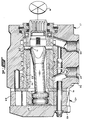
- the fluid controller 17 comprises several sections, including a valve housing 39, a port plate 41, a section comprising a fluid meter 43 (see also FIG. 1), and an end cap 45.
- the housing 39 defines an inlet port 47, a return port 49, and a pair of control (actuator) ports 51 and 53 (which are shown only schematically, and only in FIG. 1).
- the control port 51 is connected to the fluid motor 19 by means of a conduit 51c, while the control port 53 is connected to the fluid motor 19 by means of a conduit 53c, it being understood that either conduit 51c or 53c may be "high” pressure, depending upon whether a left or right turn is being made.
- conduit 51c or 53c may be "high” pressure, depending upon whether a left or right turn is being made.
- the controller 17 is really a fluid metering device, the difference in pressure between the conduits 51c and 53c may be fairly small, and terms such as "high” and “low” are used more to indicate direction of flow, to and from the fluid motor 19, respectively.
- the valve housing 39 defines a cylindrical valve bore 55, and disposed therein is the controller valving, generally designated 57 (see FIG. 1).
- the controller valving 57 typically includes a primary, rotatable valve member (spool) 61, and a cooperating, relatively rotatable follow-up valve member (sleeve) 63.
- the spool valve 61 is directly, and mechanically connected to the vehicle steering wheel W, as is well known.
- the present invention is not limited to any particular design of fluid controller, valving, etc., except as is specifically set forth in the appended claims.
- the fluid meter 43 may be of any suitable construction, but in the subject embodiment, comprises a gerotor gear set including an internally toothed stator or ring 65, and an externally toothed rotor or star 67.
- the functions of the fluid meter 43 are to "meter" or measure the flow of fluid through the meter 47, and then to provide a follow-up movement to the controller valving 57, with the amount of follow-up movement being proportional to the flow of fluid through the fluid meter 43.
- the follow-up movement is transmitted to the sleeve valve 63 by means of a main drive shaft 69 and a drive pin 71.
- a mechanical feedback 73 which comprises the drive shaft 69 and the drive pin 71 of FIG. 2.
- the system includes a device, shown schematically as a position sensor 75 mounted on, or in association with, the steering column, to generate a signal representative of the position, rotationally, of the steering wheel W.
- the steering wheel position signal is transmitted by an electrical lead 77 to the control logic 31, the reference numeral "77" hereinafter also referring to the position signal itself.
- the steering wheel position signal 77 may be viewed as the input to the logic, whereas the steered wheel position signal 37 may be viewed as the signal which the logic controls.
- the signal 37 effectively becomes the input to the logic 31
- the signal 77 effectively becomes the signal which is controlled by the logic.
- one function of the logic 31 is to compare the steered wheel position 37 to the steering wheel position 77, and generate an "error" signal representing the difference therebetween, in a manner generally well known in the controls art.
- error signal it will be understood that to some extent the existence of an error signal is only theoretical, as it is the purpose of the control logic continually to "zero out” the error signal, i.e., eliminate any difference between the actual and commanded steered wheel positions.
- the signal 37 changes to reflect this fact, until the steered wheels (or the fluid motor 19) eventually reach a mechanical stop, so that neither the steered wheels nor the motor can turn any further.
- the logic 31 modifies the signal 33, to begin to close the pressure reducing/relieving valve 15 somewhat, thus building a pressure differential across the valve 15. The result will be a higher pressure in the conduit 21 than in the conduit 13a leading to the inlet port 47 of the controller 17.
- references hereinafter and in the appended claims to the "additional fluid path" 21 generating a pressure greater than that in the high pressure path (51c or 53c) will be understood to mean and include any sort of valve means or other pressure reducing/relieving means which is capable of causing the pressure in the conduit 21 to be higher than that in the conduit 13a, or conversely, which is capable of causing the pressure in the conduit 13a to be less than that ill the conduit 21.
- the logic 31 also changes the signal 27 being transmitted to the electromagnetic valve 23, assuming that the control port 51 is connected to the inlet of the fluid motor 19. In this assumed scenario, the signal 29 remains as it was during normal steering, and the valve 25 remains closed.
- the relatively higher pressure in the conduit 21 is communicated to the high pressure conduit 51c, but because the fluid motor 19 is already stopped, the higher pressure can't turn (displace) the motor 19 any further, and the position of the steered wheels remains unchanged.
- the relatively higher pressure in the conduit 51c i.e., relatively "higher” compared to that at the inlet port 47
- the relatively higher pressure in the conduit 51c has the effect of preventing the meter 43 from turning further, in the same direction, because of the presence of a pressure differential acting on the fluid meter 43, with the relatively higher pressure being on the "output" side of the meter.
- travel limit slip of the steering wheel W is prevented.
- An additional function accomplished by the present invention is that the pressurized fluid communicated through the valve 23 into the conduit 51c effectively "saturates" the leakage in the system, i.e., the incoming pressurized fluid is at least sufficient to compensate for any leakage, without there being undesirable movement of the steering wheel W, as a result of such leakage.
- the object of the invention is to apply a sufficient reverse torque on the fluid meter, whenever the stops are reached, to prevent any further rotation of the steering input device.
- it is not satisfactory merely to apply a reverse pressure differential across the fluid meter, because it is not desired to actually drive the meter and the steering wheel in the reverse direction., i.e., opposite to the direction which was selected by the vehicle operator as he steered into the stops.
- a reverse pressure differential across the fluid meter because it is not desired to actually drive the meter and the steering wheel in the reverse direction., i.e., opposite to the direction which was selected by the vehicle operator as he steered into the stops.
- what is desired is now to control the pressure differential between the conduit 21 and the inlet port 47 so that, as long as the steered wheels are against the stops, the steering wheel W will remain substantially stationary, even in response to variations in torque applied by the operator to the steering wheel.
- any attempt by the vehicle operator to turn the steering wheel further will be sensed by a change in the signal 77, causing the pressure reducing/relieving valve 15 to close further, thereby increasing the pressure differential across the fluid meter 43.
- the system generates an appropriate reverse torque on the fluid meter 43, such that the end result is always substantially zero actual movement of the steering wheel W.
- the signal 33 will be modified accordingly by the logic 31, and the pressure reducing/relieving valve 15 will begin to open proportionately. As this occurs, the pressure differential between the conduit 21 and the inlet port 47 will be reduced, and the system will resume its normal function of maintaining correspondence or registry of the position of the steered wheels relative to the position of the steering wheel.
Landscapes
- Engineering & Computer Science (AREA)
- Chemical & Material Sciences (AREA)
- Combustion & Propulsion (AREA)
- Transportation (AREA)
- Mechanical Engineering (AREA)
- Power Steering Mechanism (AREA)
- Steering Control In Accordance With Driving Conditions (AREA)
Applications Claiming Priority (2)
| Application Number | Priority Date | Filing Date | Title |
|---|---|---|---|
| US09/028,218 US5960694A (en) | 1998-02-23 | 1998-02-23 | Hydrostatic power steering system having reduced wheel slip |
| US28218 | 1998-02-23 |
Publications (3)
| Publication Number | Publication Date |
|---|---|
| EP0937628A2 true EP0937628A2 (fr) | 1999-08-25 |
| EP0937628A3 EP0937628A3 (fr) | 2001-06-27 |
| EP0937628B1 EP0937628B1 (fr) | 2003-09-24 |
Family
ID=21842204
Family Applications (1)
| Application Number | Title | Priority Date | Filing Date |
|---|---|---|---|
| EP99102401A Expired - Lifetime EP0937628B1 (fr) | 1998-02-23 | 1999-02-08 | Système de direction assistée hydrostatique avec patinage de roues réduit |
Country Status (6)
| Country | Link |
|---|---|
| US (1) | US5960694A (fr) |
| EP (1) | EP0937628B1 (fr) |
| JP (1) | JP4314394B2 (fr) |
| KR (1) | KR100565980B1 (fr) |
| BR (1) | BR9900506A (fr) |
| DE (1) | DE69911482T2 (fr) |
Cited By (3)
| Publication number | Priority date | Publication date | Assignee | Title |
|---|---|---|---|---|
| EP1048549A2 (fr) * | 1999-04-29 | 2000-11-02 | Eaton Corporation | Système de direction hydrostatique de véhicules automobiles à haute vitesse |
| GB2351715A (en) * | 1999-07-06 | 2001-01-10 | Sauer Danfoss | A hydraulic steering arrangement |
| EP1354786A3 (fr) * | 2002-04-18 | 2004-06-02 | Still Gmbh | Dispositif de direction hydraulique |
Families Citing this family (12)
| Publication number | Priority date | Publication date | Assignee | Title |
|---|---|---|---|---|
| DE19945122B4 (de) * | 1999-09-21 | 2004-08-12 | Sauer-Danfoss Holding Aps | Hydraulische Steuereinrichtung |
| JP2001180508A (ja) * | 1999-12-27 | 2001-07-03 | Toyota Autom Loom Works Ltd | パワーステアリングバルブ |
| US6560961B2 (en) | 2001-09-18 | 2003-05-13 | Eaton Corporation | Steering system with ability to stop steering wheel rotation |
| US7028469B2 (en) * | 2002-10-08 | 2006-04-18 | Sauer-Danfoss Aps | Leakage compensation arrangement in a control device for a fully hydraulic steering system |
| JP2004314938A (ja) * | 2003-03-31 | 2004-11-11 | Komatsu Ltd | 履帯張力調整装置 |
| JP4760170B2 (ja) * | 2005-07-05 | 2011-08-31 | 株式会社豊田自動織機 | 操舵装置 |
| DE102008007736A1 (de) * | 2007-02-08 | 2008-08-21 | Sauer-Danfoss Aps | Hydraulisches Lenksystem |
| US8676445B2 (en) * | 2010-04-27 | 2014-03-18 | Ford Global Technologies, Llc | Hydraulic steering diagnostic system and method |
| EP2610142B1 (fr) | 2011-12-27 | 2014-03-05 | Sauer-Danfoss ApS | Dispositif de direction hydraulique |
| EP2610137B1 (fr) * | 2011-12-28 | 2014-03-05 | Sauer-Danfoss ApS | Dispositif de direction hydraulique |
| EP3315386B1 (fr) | 2015-06-23 | 2020-08-19 | Eaton Intelligent Power Limited | Dispositif de direction pour une machine de construction/de transport/d'agriculture |
| US10633015B2 (en) | 2017-04-14 | 2020-04-28 | Deere & Company | Hydraulic steering system |
Citations (2)
| Publication number | Priority date | Publication date | Assignee | Title |
|---|---|---|---|---|
| US3801239A (en) | 1972-04-03 | 1974-04-02 | Eaton Corp | Controller for fluid operated device |
| US5136844A (en) | 1990-10-11 | 1992-08-11 | Eaton Corportaion | Controller with reduced travel limit slip |
Family Cites Families (6)
| Publication number | Priority date | Publication date | Assignee | Title |
|---|---|---|---|---|
| US4703819A (en) * | 1985-02-27 | 1987-11-03 | Nissan Motor Co., Ltd. | Full hydraulic power steering system |
| JPH0624949B2 (ja) * | 1986-04-10 | 1994-04-06 | 日産自動車株式会社 | 全油圧式パワ−ステアリング装置 |
| JPS63212179A (ja) * | 1987-02-27 | 1988-09-05 | Komatsu Ltd | ステアリング用油圧制御装置 |
| JP2669474B2 (ja) * | 1989-07-12 | 1997-10-27 | 住友イートン機器株式会社 | 全油圧式パワーステアリング装置 |
| US5303636A (en) * | 1990-04-23 | 1994-04-19 | Eaton Corporation | Fluid controller and logic control system for use therewith |
| US5289892A (en) * | 1990-09-26 | 1994-03-01 | Nissan Diesel Motor Co., Ltd. | Steerable trailer and steering apparatus of combination vehicle |
-
1998
- 1998-02-23 US US09/028,218 patent/US5960694A/en not_active Expired - Lifetime
-
1999
- 1999-02-08 DE DE69911482T patent/DE69911482T2/de not_active Expired - Lifetime
- 1999-02-08 EP EP99102401A patent/EP0937628B1/fr not_active Expired - Lifetime
- 1999-02-20 KR KR1019990005713A patent/KR100565980B1/ko not_active IP Right Cessation
- 1999-02-23 JP JP04471199A patent/JP4314394B2/ja not_active Expired - Fee Related
- 1999-02-23 BR BR9900506-9A patent/BR9900506A/pt not_active IP Right Cessation
Patent Citations (2)
| Publication number | Priority date | Publication date | Assignee | Title |
|---|---|---|---|---|
| US3801239A (en) | 1972-04-03 | 1974-04-02 | Eaton Corp | Controller for fluid operated device |
| US5136844A (en) | 1990-10-11 | 1992-08-11 | Eaton Corportaion | Controller with reduced travel limit slip |
Cited By (5)
| Publication number | Priority date | Publication date | Assignee | Title |
|---|---|---|---|---|
| EP1048549A2 (fr) * | 1999-04-29 | 2000-11-02 | Eaton Corporation | Système de direction hydrostatique de véhicules automobiles à haute vitesse |
| EP1048549A3 (fr) * | 1999-04-29 | 2003-01-02 | Eaton Corporation | Système de direction hydrostatique de véhicules automobiles à haute vitesse |
| GB2351715A (en) * | 1999-07-06 | 2001-01-10 | Sauer Danfoss | A hydraulic steering arrangement |
| EP1354786A3 (fr) * | 2002-04-18 | 2004-06-02 | Still Gmbh | Dispositif de direction hydraulique |
| US6896092B2 (en) | 2002-04-18 | 2005-05-24 | Still Gmbh | Hydraulic steering device |
Also Published As
| Publication number | Publication date |
|---|---|
| US5960694A (en) | 1999-10-05 |
| DE69911482T2 (de) | 2004-07-01 |
| JP4314394B2 (ja) | 2009-08-12 |
| EP0937628A3 (fr) | 2001-06-27 |
| JPH11291928A (ja) | 1999-10-26 |
| EP0937628B1 (fr) | 2003-09-24 |
| KR19990072806A (ko) | 1999-09-27 |
| DE69911482D1 (de) | 2003-10-30 |
| KR100565980B1 (ko) | 2006-03-30 |
| BR9900506A (pt) | 2000-01-04 |
Similar Documents
| Publication | Publication Date | Title |
|---|---|---|
| US5960694A (en) | Hydrostatic power steering system having reduced wheel slip | |
| EP1253061B1 (fr) | Dispositif de couple pour une direction de type "steer-by-wire" électronique | |
| US5020618A (en) | Full hydraulic power steering apparatus | |
| EP0038542B1 (fr) | Appareil de commande sensible à la charge | |
| CA1045940A (fr) | Systeme de direction sur vehicule | |
| EP0388711B1 (fr) | Commande de direction à amplification du débit et à centre ouvert | |
| US6560961B2 (en) | Steering system with ability to stop steering wheel rotation | |
| EP1231128B1 (fr) | Système de direction hydrostatique avec perception de direction améliorée | |
| JPH08261205A (ja) | 油圧システムの制御装置 | |
| EP0480431B1 (fr) | Dispositif de commande avec glissement réduit à déviation maximum | |
| JPH01148663A (ja) | 電子動力補助制御かじ取装置 | |
| USRE34746E (en) | Open-center steering control unit with flow amplification | |
| US6213247B1 (en) | Hydraulic steering device and method for steering a vehicle | |
| EP0561401B1 (fr) | Système de direction hydraulique assistée avec capacité de détection de l'entrée | |
| US20240034397A1 (en) | Steering system | |
| US20010032751A1 (en) | Hydraulic steering arrangement | |
| JPH05338545A (ja) | パワーステアリング装置 | |
| JPH02164673A (ja) | 全油圧式パワーステアリング装置 | |
| JPH03571A (ja) | 全油圧式パワーステアリング装置 | |
| JPS62221970A (ja) | 動力舵取装置の操舵力制御装置 |
Legal Events
| Date | Code | Title | Description |
|---|---|---|---|
| PUAI | Public reference made under article 153(3) epc to a published international application that has entered the european phase |
Free format text: ORIGINAL CODE: 0009012 |
|
| AK | Designated contracting states |
Kind code of ref document: A2 Designated state(s): DE FR GB IT SE |
|
| AX | Request for extension of the european patent |
Free format text: AL;LT;LV;MK;RO;SI |
|
| PUAL | Search report despatched |
Free format text: ORIGINAL CODE: 0009013 |
|
| AK | Designated contracting states |
Kind code of ref document: A3 Designated state(s): AT BE CH CY DE DK ES FI FR GB GR IE IT LI LU MC NL PT SE |
|
| AX | Request for extension of the european patent |
Free format text: AL;LT;LV;MK;RO;SI |
|
| 17P | Request for examination filed |
Effective date: 20011011 |
|
| AKX | Designation fees paid |
Free format text: DE FR GB IT SE |
|
| GRAH | Despatch of communication of intention to grant a patent |
Free format text: ORIGINAL CODE: EPIDOS IGRA |
|
| GRAS | Grant fee paid |
Free format text: ORIGINAL CODE: EPIDOSNIGR3 |
|
| GRAA | (expected) grant |
Free format text: ORIGINAL CODE: 0009210 |
|
| AK | Designated contracting states |
Kind code of ref document: B1 Designated state(s): DE FR GB IT SE |
|
| REG | Reference to a national code |
Ref country code: GB Ref legal event code: FG4D |
|
| REF | Corresponds to: |
Ref document number: 69911482 Country of ref document: DE Date of ref document: 20031030 Kind code of ref document: P |
|
| REG | Reference to a national code |
Ref country code: SE Ref legal event code: TRGR |
|
| ET | Fr: translation filed | ||
| PLBE | No opposition filed within time limit |
Free format text: ORIGINAL CODE: 0009261 |
|
| STAA | Information on the status of an ep patent application or granted ep patent |
Free format text: STATUS: NO OPPOSITION FILED WITHIN TIME LIMIT |
|
| 26N | No opposition filed |
Effective date: 20040625 |
|
| PGFP | Annual fee paid to national office [announced via postgrant information from national office to epo] |
Ref country code: DE Payment date: 20140228 Year of fee payment: 16 Ref country code: SE Payment date: 20140207 Year of fee payment: 16 |
|
| PGFP | Annual fee paid to national office [announced via postgrant information from national office to epo] |
Ref country code: FR Payment date: 20140128 Year of fee payment: 16 Ref country code: IT Payment date: 20140219 Year of fee payment: 16 |
|
| PGFP | Annual fee paid to national office [announced via postgrant information from national office to epo] |
Ref country code: GB Payment date: 20140128 Year of fee payment: 16 |
|
| REG | Reference to a national code |
Ref country code: DE Ref legal event code: R119 Ref document number: 69911482 Country of ref document: DE |
|
| REG | Reference to a national code |
Ref country code: SE Ref legal event code: EUG |
|
| GBPC | Gb: european patent ceased through non-payment of renewal fee |
Effective date: 20150208 |
|
| REG | Reference to a national code |
Ref country code: FR Ref legal event code: ST Effective date: 20151030 |
|
| PG25 | Lapsed in a contracting state [announced via postgrant information from national office to epo] |
Ref country code: SE Free format text: LAPSE BECAUSE OF NON-PAYMENT OF DUE FEES Effective date: 20150209 |
|
| PG25 | Lapsed in a contracting state [announced via postgrant information from national office to epo] |
Ref country code: IT Free format text: LAPSE BECAUSE OF NON-PAYMENT OF DUE FEES Effective date: 20150208 |
|
| PG25 | Lapsed in a contracting state [announced via postgrant information from national office to epo] |
Ref country code: DE Free format text: LAPSE BECAUSE OF NON-PAYMENT OF DUE FEES Effective date: 20150901 Ref country code: GB Free format text: LAPSE BECAUSE OF NON-PAYMENT OF DUE FEES Effective date: 20150208 |
|
| PG25 | Lapsed in a contracting state [announced via postgrant information from national office to epo] |
Ref country code: FR Free format text: LAPSE BECAUSE OF NON-PAYMENT OF DUE FEES Effective date: 20150302 |