EP0937507B1 - Seitenleiste für Siebmaschinen - Google Patents
Seitenleiste für Siebmaschinen Download PDFInfo
- Publication number
- EP0937507B1 EP0937507B1 EP98112810A EP98112810A EP0937507B1 EP 0937507 B1 EP0937507 B1 EP 0937507B1 EP 98112810 A EP98112810 A EP 98112810A EP 98112810 A EP98112810 A EP 98112810A EP 0937507 B1 EP0937507 B1 EP 0937507B1
- Authority
- EP
- European Patent Office
- Prior art keywords
- screening
- screen
- side rail
- screen according
- mat
- Prior art date
- Legal status (The legal status is an assumption and is not a legal conclusion. Google has not performed a legal analysis and makes no representation as to the accuracy of the status listed.)
- Expired - Lifetime
Links
- 229920001971 elastomer Polymers 0.000 claims abstract description 8
- 239000000806 elastomer Substances 0.000 claims abstract description 7
- 238000012216 screening Methods 0.000 claims description 25
- 229920003023 plastic Polymers 0.000 claims description 7
- 239000004033 plastic Substances 0.000 claims description 7
- 239000007788 liquid Substances 0.000 claims description 3
- 239000000725 suspension Substances 0.000 claims description 3
- 239000000463 material Substances 0.000 abstract 1
- 229910000831 Steel Inorganic materials 0.000 description 3
- 239000010959 steel Substances 0.000 description 3
- 238000007789 sealing Methods 0.000 description 2
- 238000004026 adhesive bonding Methods 0.000 description 1
- 239000000969 carrier Substances 0.000 description 1
- 238000010276 construction Methods 0.000 description 1
- 238000009795 derivation Methods 0.000 description 1
- 230000000694 effects Effects 0.000 description 1
- 239000004744 fabric Substances 0.000 description 1
- 238000009434 installation Methods 0.000 description 1
- 230000002028 premature Effects 0.000 description 1
- 230000002787 reinforcement Effects 0.000 description 1
- 238000003466 welding Methods 0.000 description 1
- 239000002023 wood Substances 0.000 description 1
Images
Classifications
-
- B—PERFORMING OPERATIONS; TRANSPORTING
- B07—SEPARATING SOLIDS FROM SOLIDS; SORTING
- B07B—SEPARATING SOLIDS FROM SOLIDS BY SIEVING, SCREENING, SIFTING OR BY USING GAS CURRENTS; SEPARATING BY OTHER DRY METHODS APPLICABLE TO BULK MATERIAL, e.g. LOOSE ARTICLES FIT TO BE HANDLED LIKE BULK MATERIAL
- B07B1/00—Sieving, screening, sifting, or sorting solid materials using networks, gratings, grids, or the like
- B07B1/46—Constructional details of screens in general; Cleaning or heating of screens
- B07B1/4609—Constructional details of screens in general; Cleaning or heating of screens constructional details of screening surfaces or meshes
Definitions
- the invention relates to a screening machine with plastic side strips as lateral termination of the screen area, the screen area being limited and the Connection between the screen mats and the side bar is detachable.
- Sidebars serve as wear protection for screening machines Screen machine side walls, partly for fastening the screen coverings and further for sealing the screen surfaces. They are made of steel, wood or elastomer Fabrics (rubber / plastic) that are usually made of steel reinforcements which contain rigidity and fastening. It is fastened with wedges, Screw or plug.
- a sieve bottom made of plastic sieve elements is known from EP 167 999, at between the plastic screen elements and the machine side wall Sidebars made of plastic are lying in a U-shape with lower projections Steel profile are held to the side rails one to give sufficient support.
- the object of the invention is to provide a side bar of the type mentioned improve that with simple construction and assembly and without additional fasteners provides a secure detachable hold.
- the sidebar according to the invention is safe without additional fasteners between the side wall of the machine and the screen mats clamped and positively held. Assembly and disassembly are particularly easy and in the shortest possible time perform.
- the side clamping strips are preferred for screening systems (Change systems), especially in systems that are not selective, but have a linear attachment used - preferably in the so-called Transverse installation, where the system carriers and the screen mats crosswise to the conveyor be installed in a screening machine.
- the side strips face the one facing the screen field Side has a protruding deflector that the edge of the screen mat on the Overhanging the top.
- the weight of the sidebar is reduced by the fact that the sieve panel has cutouts facing away from the rear of the side bar.
- the screen mats are longer than the clear Dimension between the sidebars.
- the sidebar stabilizes the back Ribs. It is preferably proposed that the sidebar be made of an elastomer.
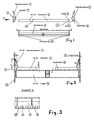
- the screening machine has a screening field made up of individual screening mats 2 Elastomers preferably made of plastic, which are known side by side Fastening strips (adapter strips) 3 are attached to cross members 11, the extend between the two machine side walls 12. To the Sidewalls are inside sides (clamp) that are between the Pressed side walls and the outer end faces 14 of the screen mats 2 become. They are held there because the length of the screen mats is a bit is chosen larger than the clear dimension between the two side strips.
- the sieve mats have on the end face 14 towards the sieve machine side wall 12 a spring 5 worked into the groove 4 of the side terminal block 1 intervenes and is thus securely fixed.
- an underlap 13 of the adapter profile is provided.
- the screen mat makes sense to split it into two parts 2a, 2b perform.
- the screen mat lengths are alternating chosen differently.
- the sidebar is made so that it is in the relaxed state in the upper Area of the machine wall (12) and in the lower area (counter bearing) protrudes from the machine side wall by a certain distance.
- the screen mat (2) by pressing the side bar Vertical sieve mat deformed until the counter bearing (6) on the Fitting the machine side wall. This creates a contact pressure of the upper one Area of the sidebar against the machine side wall and a Sealing achieved.
Landscapes
- Combined Means For Separation Of Solids (AREA)
- Testing Of Devices, Machine Parts, Or Other Structures Thereof (AREA)
- Fertilizing (AREA)
- Investigation Of Foundation Soil And Reinforcement Of Foundation Soil By Compacting Or Drainage (AREA)
- Paper (AREA)
- Treatment Of Sludge (AREA)
Description
- Fig. 1
- Siebmatten, Seitenklemmleiste und Adapterprofil im auseinander genommenen Zustand,
- Fig. 2
- Siebmaschine mit Teilen nach Fig. 1 im senkrechten Schnitt,
- Fig. 3
- eine Ansicht nach Pfeil A in Fig. 1,
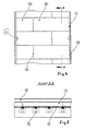
- Fig. 4
- eine Draufsicht auf die Siebmaschine und den Siebbelag von oben, und
- Fig. 5
- einen Schnitt nach B-B in Fig. 4.
Claims (11)
- Siebmaschine mit Seitenleisten (1) aus Kunststoff als seitlicher Abschluss des Siebfeldes, wobei das Siebfeld (12) Siebmatten (2) aufweist und von einer Maschinenseitenwand begrenzt ist und die Verbindung zwischen den Siebmatten und der Seitenleiste lösbar ist, dadurch gekennzeichnet, dass die Seitenleiste (1) kraftschlüssig zwischen der äußeren Stirnseite (14) der Siebmatte (2) und der Seitenwand (12) eingeklemmt ist, und zwischen der Seitenleiste (1) und der Siebmattenstirnseite (14) eine formschlüssige Verbindung besteht, bei der die Seitenleiste (1) eine waagerechte Nut (4) aufweist, in die ein auf der Stirnseite (14) der Siebmatte angeordneter Vorsprung, insbesondere eine Feder (5) eingreift.
- Siebmaschine nach Anspruch 1, dadurch gekennzeichnet, dass die Seitenleiste (1) auf der dem Siebfeld zugewandten Seite einen vorspringenden Abweiser (7) aufweist, der den Siebmattenrand an der Oberseite überragt.
- Siebmaschine nach einem der vorherigen Ansprüche, dadurch gekennzeichnet, dass an der Rückseite der Seitenleiste (1) Vorsprünge insbesondere in Form von Noppen (6) als Gegenlager vorstehen, die gegen die Maschinenseitenwände (12) anliegen.
- Siebmaschine nach Anspruch 3, dadurch gekennzeichnet, dass zwischen den Vorsprüngen (6) Freiräume (15) zur Ableitung von Flüssigkeiten, insbesondere einer Suspension sind.
- Siebmaschine nach einem der vorherigen Ansprüche, dadurch gekennzeichnet, dass die dem Siebfeld abgewandte Rückseite der Seitenleiste (1) Aussparungen aufweist.
- Siebmaschine nach einem der vorherigen Ansprüche, dadurch gekennzeichnet, dass für einen Presssitz die Siebmatten (2) länger sind als das lichte Maß zwischen den Seitenleisten.
- Siebmaschine nach einem der vorherigen Ansprüche, dadurch gekennzeichnet, dass die Siebmatten (2) durch ein Adapterprofil (3) an unter dem Siebfeld angeordneten Querträgern (11) gehalten sind.
- Siebmaschine nach Anspruch 7, dadurch gekennzeichnet, dass das Adapterprofil (3) die Seitenleiste (1) untergreift.
- Siebmaschine nach einem der vorherigen Ansprüche, dadurch gekennzeichnet, dass sie (1) rückseitig stabilisierende Rippen (8) aufweist.
- Siebmaschine nach einem der vorherigen Ansprüche, dadurch gekennzeichnet, dass die Seitenleiste (1) aus einem Elastomer besteht.
- Siebmaschine nach einem der vorherigen Ansprüche, dadurch gekennzeichnet, dass die Seitenleiste so gefertigt ist, dass sie im entspannten Zustand im oberen Bereich der Maschinenwand (12) ansteht und im unteren Bereich (Gegenlager) von der Maschinenseitenwand mit einer gewissen Distanz absteht.
Applications Claiming Priority (2)
| Application Number | Priority Date | Filing Date | Title |
|---|---|---|---|
| DE19807162 | 1998-02-20 | ||
| DE19807162A DE19807162C2 (de) | 1998-02-20 | 1998-02-20 | Siebmaschine mit Seitenleiste |
Publications (3)
| Publication Number | Publication Date |
|---|---|
| EP0937507A2 EP0937507A2 (de) | 1999-08-25 |
| EP0937507A3 EP0937507A3 (de) | 2000-05-31 |
| EP0937507B1 true EP0937507B1 (de) | 2003-01-02 |
Family
ID=7858408
Family Applications (1)
| Application Number | Title | Priority Date | Filing Date |
|---|---|---|---|
| EP98112810A Expired - Lifetime EP0937507B1 (de) | 1998-02-20 | 1998-07-10 | Seitenleiste für Siebmaschinen |
Country Status (4)
| Country | Link |
|---|---|
| EP (1) | EP0937507B1 (de) |
| AT (1) | ATE230310T1 (de) |
| DE (2) | DE19807162C2 (de) |
| ES (1) | ES2189044T3 (de) |
Families Citing this family (1)
| Publication number | Priority date | Publication date | Assignee | Title |
|---|---|---|---|---|
| AT412788B (de) * | 2003-10-15 | 2005-07-25 | Andritz Ag Maschf | Sieb- bzw. sortiervorrichtung |
Family Cites Families (6)
| Publication number | Priority date | Publication date | Assignee | Title |
|---|---|---|---|---|
| DE7918167U1 (de) * | 1979-06-25 | 1979-09-27 | Mogensen Gmbh & Co Kg, 2000 Wedel | Profilschiene, insbesondere fuer die abdichtung an siebvorrichtungen |
| DE3425485A1 (de) * | 1984-07-11 | 1986-01-16 | Hein, Lehmann AG, 4000 Düsseldorf | Siebbelag |
| DE3521753A1 (de) * | 1985-06-18 | 1986-12-18 | Hein, Lehmann AG, 4000 Düsseldorf | Siebmaschine mit einem an querelementen befestigten siebbelag |
| DE3526767A1 (de) * | 1985-07-26 | 1987-01-29 | Hein Lehmann Ag | Abdichtung fuer eine siebmaschine |
| AT386137B (de) * | 1987-02-23 | 1988-07-11 | Binder Co Ag | Siebmaschinenabdichtung |
| US5112475A (en) * | 1990-08-06 | 1992-05-12 | Conn-Weld Industries, Inc. | Panel mounting system |
-
1998
- 1998-02-20 DE DE19807162A patent/DE19807162C2/de not_active Expired - Fee Related
- 1998-07-10 DE DE59806813T patent/DE59806813D1/de not_active Expired - Fee Related
- 1998-07-10 EP EP98112810A patent/EP0937507B1/de not_active Expired - Lifetime
- 1998-07-10 AT AT98112810T patent/ATE230310T1/de not_active IP Right Cessation
- 1998-07-10 ES ES98112810T patent/ES2189044T3/es not_active Expired - Lifetime
Also Published As
| Publication number | Publication date |
|---|---|
| DE59806813D1 (de) | 2003-02-06 |
| EP0937507A3 (de) | 2000-05-31 |
| ATE230310T1 (de) | 2003-01-15 |
| DE19807162A1 (de) | 1999-08-26 |
| ES2189044T3 (es) | 2003-07-01 |
| DE19807162C2 (de) | 2001-05-23 |
| EP0937507A2 (de) | 1999-08-25 |
Similar Documents
| Publication | Publication Date | Title |
|---|---|---|
| EP0118800B1 (de) | Siebbelag mit auswechselbaren Siebelementen | |
| EP0167999B2 (de) | Siebbelag | |
| EP0363725B1 (de) | Siebboden | |
| AT509674B1 (de) | Halterung für ein rahmenloses, flächiges glaselement | |
| EP1431501B1 (de) | Schiebetüranlage | |
| EP0696667B1 (de) | Profilschienensystem zum Überbrücken von Fugen oder Rändern bei Belägen | |
| AT509055B1 (de) | Vorrichtung zur befestigung einer backenschiene | |
| DE202007007362U1 (de) | Rinnenschuss mit Wechseltrog, Wechseltrog sowie Obertrumbefestigungsmittel hierfür | |
| EP0750090A2 (de) | Linearverbinder aus Kunststoff zur Verbindung von hohlen Abstandhalterprofilen von Mehrscheibenisoliergläsern | |
| DE10252922B3 (de) | Membranfilterpresse | |
| DE9301241U1 (de) | Stahltür mit einer bodenseitigen automatischen Dichtungsvorrichtung | |
| DE19807162C2 (de) | Siebmaschine mit Seitenleiste | |
| AU742060B2 (en) | Screening assembly | |
| EP0523282B1 (de) | Abstützteil für Glasscheiben von Fenstern, Türen od. dgl. | |
| EP0239823B1 (de) | Schiebeflügel für Fenster oder Türen | |
| DE4308982C2 (de) | Förderband | |
| DE20204123U1 (de) | Siebbelag, Seitenschutz für einen Siebbelag und Siebvorrichtung mit einem solchen Siebbelag | |
| DE4026515C1 (en) | Expansion joint for roadway - has edging bars and inner bars connected by stretched elastic strip | |
| DE4329879A1 (de) | Siebmaschine | |
| EP1057544B1 (de) | Siebbelag mit Stauleiste | |
| EP0212639B1 (de) | Torabdichtung, insbesondere Verladetorabdichtung | |
| AT527638B1 (de) | Becher für ein Gurtbecherwerk und Gurtbecherwerk | |
| WO1991009798A1 (de) | Dichtungssystem für förderbandübergabeschurren, und dergleichen | |
| DE4225173A1 (de) | Siebbelag | |
| EP0009584B1 (de) | Fugenabdeckung für Dehnungsfugen in Verkehrswegen, insbesondere Brücken |
Legal Events
| Date | Code | Title | Description |
|---|---|---|---|
| PUAI | Public reference made under article 153(3) epc to a published international application that has entered the european phase |
Free format text: ORIGINAL CODE: 0009012 |
|
| AK | Designated contracting states |
Kind code of ref document: A2 Designated state(s): AT BE CH CY DE DK ES FI FR GB GR IE IT LI LU MC NL PT SE |
|
| AX | Request for extension of the european patent |
Free format text: AL;LT PAYMENT 19980710;LV PAYMENT 19980710;MK;RO PAYMENT 19980710;SI PAYMENT 19980710 |
|
| PUAL | Search report despatched |
Free format text: ORIGINAL CODE: 0009013 |
|
| AK | Designated contracting states |
Kind code of ref document: A3 Designated state(s): AT BE CH CY DE DK ES FI FR GB GR IE IT LI LU MC NL PT SE |
|
| AX | Request for extension of the european patent |
Free format text: AL;LT PAYMENT 19980710;LV PAYMENT 19980710;MK;RO PAYMENT 19980710;SI PAYMENT 19980710 |
|
| 17P | Request for examination filed |
Effective date: 20000531 |
|
| AKX | Designation fees paid |
Free format text: AT BE CH CY DE DK ES FI FR GB GR IE IT LI LU MC NL PT SE |
|
| AXX | Extension fees paid |
Free format text: LT PAYMENT 19980710;LV PAYMENT 19980710;RO PAYMENT 19980710;SI PAYMENT 19980710 |
|
| 17Q | First examination report despatched |
Effective date: 20010816 |
|
| GRAH | Despatch of communication of intention to grant a patent |
Free format text: ORIGINAL CODE: EPIDOS IGRA |
|
| GRAH | Despatch of communication of intention to grant a patent |
Free format text: ORIGINAL CODE: EPIDOS IGRA |
|
| GRAA | (expected) grant |
Free format text: ORIGINAL CODE: 0009210 |
|
| AK | Designated contracting states |
Kind code of ref document: B1 Designated state(s): AT BE CH CY DE DK ES FI FR GB GR IE IT LI LU MC NL PT SE |
|
| AX | Request for extension of the european patent |
Free format text: LT PAYMENT 19980710;LV PAYMENT 19980710;RO PAYMENT 19980710;SI PAYMENT 19980710 |
|
| PG25 | Lapsed in a contracting state [announced via postgrant information from national office to epo] |
Ref country code: IE Free format text: LAPSE BECAUSE OF FAILURE TO SUBMIT A TRANSLATION OF THE DESCRIPTION OR TO PAY THE FEE WITHIN THE PRESCRIBED TIME-LIMIT Effective date: 20030102 Ref country code: GR Free format text: LAPSE BECAUSE OF FAILURE TO SUBMIT A TRANSLATION OF THE DESCRIPTION OR TO PAY THE FEE WITHIN THE PRESCRIBED TIME-LIMIT Effective date: 20030102 Ref country code: FI Free format text: LAPSE BECAUSE OF FAILURE TO SUBMIT A TRANSLATION OF THE DESCRIPTION OR TO PAY THE FEE WITHIN THE PRESCRIBED TIME-LIMIT Effective date: 20030102 |
|
| REF | Corresponds to: |
Ref document number: 230310 Country of ref document: AT Date of ref document: 20030115 Kind code of ref document: T |
|
| REG | Reference to a national code |
Ref country code: GB Ref legal event code: FG4D Free format text: 20030102:NOT ENGLISH |
|
| REG | Reference to a national code |
Ref country code: CH Ref legal event code: EP |
|
| REG | Reference to a national code |
Ref country code: IE Ref legal event code: FG4D Free format text: GERMAN |
|
| REF | Corresponds to: |
Ref document number: 59806813 Country of ref document: DE Date of ref document: 20030206 Kind code of ref document: P |
|
| REG | Reference to a national code |
Ref country code: SE Ref legal event code: TRGR |
|
| PG25 | Lapsed in a contracting state [announced via postgrant information from national office to epo] |
Ref country code: PT Free format text: LAPSE BECAUSE OF FAILURE TO SUBMIT A TRANSLATION OF THE DESCRIPTION OR TO PAY THE FEE WITHIN THE PRESCRIBED TIME-LIMIT Effective date: 20030402 Ref country code: DK Free format text: LAPSE BECAUSE OF FAILURE TO SUBMIT A TRANSLATION OF THE DESCRIPTION OR TO PAY THE FEE WITHIN THE PRESCRIBED TIME-LIMIT Effective date: 20030402 |
|
| GBT | Gb: translation of ep patent filed (gb section 77(6)(a)/1977) |
Effective date: 20030501 |
|
| LTIE | Lt: invalidation of european patent or patent extension |
Effective date: 20030102 |
|
| REG | Reference to a national code |
Ref country code: ES Ref legal event code: FG2A Ref document number: 2189044 Country of ref document: ES Kind code of ref document: T3 |
|
| PG25 | Lapsed in a contracting state [announced via postgrant information from national office to epo] |
Ref country code: LU Free format text: LAPSE BECAUSE OF NON-PAYMENT OF DUE FEES Effective date: 20030710 Ref country code: CY Free format text: LAPSE BECAUSE OF FAILURE TO SUBMIT A TRANSLATION OF THE DESCRIPTION OR TO PAY THE FEE WITHIN THE PRESCRIBED TIME-LIMIT Effective date: 20030710 |
|
| ET | Fr: translation filed | ||
| PG25 | Lapsed in a contracting state [announced via postgrant information from national office to epo] |
Ref country code: MC Free format text: LAPSE BECAUSE OF NON-PAYMENT OF DUE FEES Effective date: 20030731 Ref country code: LI Free format text: LAPSE BECAUSE OF NON-PAYMENT OF DUE FEES Effective date: 20030731 Ref country code: CH Free format text: LAPSE BECAUSE OF NON-PAYMENT OF DUE FEES Effective date: 20030731 |
|
| REG | Reference to a national code |
Ref country code: IE Ref legal event code: FD4D Ref document number: 0937507E Country of ref document: IE |
|
| PLBE | No opposition filed within time limit |
Free format text: ORIGINAL CODE: 0009261 |
|
| STAA | Information on the status of an ep patent application or granted ep patent |
Free format text: STATUS: NO OPPOSITION FILED WITHIN TIME LIMIT |
|
| 26N | No opposition filed |
Effective date: 20031003 |
|
| REG | Reference to a national code |
Ref country code: CH Ref legal event code: PL |
|
| PGFP | Annual fee paid to national office [announced via postgrant information from national office to epo] |
Ref country code: AT Payment date: 20050622 Year of fee payment: 8 |
|
| PGFP | Annual fee paid to national office [announced via postgrant information from national office to epo] |
Ref country code: NL Payment date: 20050703 Year of fee payment: 8 |
|
| PGFP | Annual fee paid to national office [announced via postgrant information from national office to epo] |
Ref country code: GB Payment date: 20050706 Year of fee payment: 8 Ref country code: SE Payment date: 20050706 Year of fee payment: 8 |
|
| PGFP | Annual fee paid to national office [announced via postgrant information from national office to epo] |
Ref country code: DE Payment date: 20050707 Year of fee payment: 8 |
|
| PGFP | Annual fee paid to national office [announced via postgrant information from national office to epo] |
Ref country code: FR Payment date: 20050708 Year of fee payment: 8 |
|
| PGFP | Annual fee paid to national office [announced via postgrant information from national office to epo] |
Ref country code: ES Payment date: 20050818 Year of fee payment: 8 |
|
| PGFP | Annual fee paid to national office [announced via postgrant information from national office to epo] |
Ref country code: BE Payment date: 20050915 Year of fee payment: 8 |
|
| PG25 | Lapsed in a contracting state [announced via postgrant information from national office to epo] |
Ref country code: GB Free format text: LAPSE BECAUSE OF NON-PAYMENT OF DUE FEES Effective date: 20060710 Ref country code: AT Free format text: LAPSE BECAUSE OF NON-PAYMENT OF DUE FEES Effective date: 20060710 |
|
| PG25 | Lapsed in a contracting state [announced via postgrant information from national office to epo] |
Ref country code: SE Free format text: LAPSE BECAUSE OF NON-PAYMENT OF DUE FEES Effective date: 20060711 |
|
| PG25 | Lapsed in a contracting state [announced via postgrant information from national office to epo] |
Ref country code: BE Free format text: LAPSE BECAUSE OF NON-PAYMENT OF DUE FEES Effective date: 20060731 |
|
| PGFP | Annual fee paid to national office [announced via postgrant information from national office to epo] |
Ref country code: IT Payment date: 20060731 Year of fee payment: 9 |
|
| PG25 | Lapsed in a contracting state [announced via postgrant information from national office to epo] |
Ref country code: NL Free format text: LAPSE BECAUSE OF NON-PAYMENT OF DUE FEES Effective date: 20070201 Ref country code: DE Free format text: LAPSE BECAUSE OF NON-PAYMENT OF DUE FEES Effective date: 20070201 |
|
| EUG | Se: european patent has lapsed | ||
| GBPC | Gb: european patent ceased through non-payment of renewal fee |
Effective date: 20060710 |
|
| NLV4 | Nl: lapsed or anulled due to non-payment of the annual fee |
Effective date: 20070201 |
|
| REG | Reference to a national code |
Ref country code: FR Ref legal event code: ST Effective date: 20070330 |
|
| REG | Reference to a national code |
Ref country code: ES Ref legal event code: FD2A Effective date: 20060711 |
|
| BERE | Be: lapsed |
Owner name: *ISENMANN SIEBE G.M.B.H. Effective date: 20060731 |
|
| PG25 | Lapsed in a contracting state [announced via postgrant information from national office to epo] |
Ref country code: ES Free format text: LAPSE BECAUSE OF NON-PAYMENT OF DUE FEES Effective date: 20060711 |
|
| PG25 | Lapsed in a contracting state [announced via postgrant information from national office to epo] |
Ref country code: FR Free format text: LAPSE BECAUSE OF NON-PAYMENT OF DUE FEES Effective date: 20060731 |
|
| PG25 | Lapsed in a contracting state [announced via postgrant information from national office to epo] |
Ref country code: IT Free format text: LAPSE BECAUSE OF NON-PAYMENT OF DUE FEES Effective date: 20070710 |