EP0936147B1 - Machine de liage - Google Patents
Machine de liage Download PDFInfo
- Publication number
- EP0936147B1 EP0936147B1 EP99102991A EP99102991A EP0936147B1 EP 0936147 B1 EP0936147 B1 EP 0936147B1 EP 99102991 A EP99102991 A EP 99102991A EP 99102991 A EP99102991 A EP 99102991A EP 0936147 B1 EP0936147 B1 EP 0936147B1
- Authority
- EP
- European Patent Office
- Prior art keywords
- binding
- bag
- binding piece
- piece
- trigger lever
- Prior art date
- Legal status (The legal status is an assumption and is not a legal conclusion. Google has not performed a legal analysis and makes no representation as to the accuracy of the status listed.)
- Expired - Fee Related
Links
Images


Classifications
-
- B—PERFORMING OPERATIONS; TRANSPORTING
- B65—CONVEYING; PACKING; STORING; HANDLING THIN OR FILAMENTARY MATERIAL
- B65B—MACHINES, APPARATUS OR DEVICES FOR, OR METHODS OF, PACKAGING ARTICLES OR MATERIALS; UNPACKING
- B65B51/00—Devices for, or methods of, sealing or securing package folds or closures; Devices for gathering or twisting wrappers, or necks of bags
- B65B51/04—Applying separate sealing or securing members, e.g. clips
- B65B51/043—Applying springy clips around bag necks
Definitions
- the present invention relates to a binding machine according to the preamble of claim 1.
- a binding machine is known from US-A-5485711.
- a binding machine which binds an opening of a bag made of a resin such as polyethylene and containing an article(s) to be packed
- a binding machine hereinafter simply named as a bag binder, which automatically fastens a resin binding piece that can be easily attached and detached so as to be repeatedly used, to an opening of a bag
- Fig. 1 shows the bag binder 1.
- Binding pieces 2 which are configured by a resin plate and linked to one another into a belt-like shape are housed in a binding piece magazine 3.
- the binding pieces are sequentially fed to a binding device 6 by ratchet pawls 5 of a binding-piece feeding mechanism 4.
- a cutter (not shown) which is interlocked with the forward movement of the binding-piece feeding mechanism 4 cuts the portion where the leading binding piece 2a and the next binding piece 2b are linked to each other, and a twisting arm 7 of the binding device 6 rotates to twist two legs of the leading binding piece 2a.
- the tip ends of the legs are restricted in rotation by a fixed forming jig 8, and hence the binding piece 2a twisted by the twisting arm 7 is bent into a funnel-like shape, so that hooking portions of the tip ends are crosswise engaged with each other.
- the binding piece 2 is twisted by the twisting arm 7 so as to be fastened to the bag, and hence a space for rotation of the twisting arm 7 and the binding piece 2 must be ensured.
- the bag B cannot be bound in a tension state, and the binding piece is attached to an upper position which is separated from the contents of the bag.
- a room in which the contents can be moved is formed in the bag.
- the press bonding is performed by forming means for forming a dowel shape, and crimping means for crimping the dowel shape.
- the bag binder attaches a binding piece to a puckered portion of a bag by pressing the outer side of the legs of the binding piece.
- a binding piece can be attached to a bag in close proximity to contents of the bag, so that the bag is bound in a tension state.
- the second object can be attained by a bag binder comprising: a binding-piece feeding member which fits a binding piece onto a puckered portion of a bag, the binding piece being formed by a portal flat plate of a synthetic resin; a binding, member which presses legs of the binding piece in a closing direction, thereby crossing the legs with each other; and a waiting position controller for a bag binder.
- the binding member crosswise engages or press-bonds the legs with each other.
- the bag binder performs one cycle of a binding operation by one rotation of a main gear which is driven by a motor.
- the waiting position controller stops a driving of the motor in accordance with end-of-cycle detecting means such as a switch, thereby stopping the feeding member and the binding member at waiting positions.
- a disk is coaxially attached to the main gear.
- An index portion such as a notch or a mirror portion is formed in an edge portion of the disk, and a photo-sensor which detects the index portion is disposed, thereby constituting rotary end-of-cycle detecting means.
- Controlling means is disposed for starting breaking of a driving system, in response to an index portion detection signal from the photo-sensor, and for stopping the motor, at a timing when the index portion detection signal is turned off.
- a binding machine for binding a bag comprising: a binding-piece feeding member for feeding a binding piece to a position adjacent to the bag, the binding piece made of a synthetic resin and including a pair of leg portions for binding the bag; a crossing member for crossing the leg portions by pressing the leg portions of the binding pieces; a bonding member for bonding the leg portions of the binding pieces each other so as to crosswise engage a crossed portion of the leg portions each other; and a controller for controlling a binding operation with the binding-piece feeding member, the crossing member, and the bonding member.
- the controller comprising; a main gear driven by a motor, one rotation of which performs one cycle of the binding operation; a disk coaxially attached to the main gear, the disk including an index portion provided at an edge portion of the disk; and a photo-sensor detecting the index portion so as to detect one cycle of the binding operation.
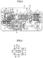
- FIG. 3 shows a bag binder 11.
- a binding device 14 and a crimping device 15 are opposed to each other across a guiding groove 13 which is downward formed from the upper face of the front portion of the outer case 12.
- the binding device 14 and the crimping device 15 are driven by a motor 16 and a reduction gear mechanism 17, and the crimping device 15 is driven by the reduction gear mechanism 17 via a cam 18, a slider 19, and a lever 20.
- a trigger arm 21 When an opening portion of a resin bag is puckered and inserted into the guiding groove 13, a trigger arm 21 is pushed by the bag to downward swing, whereby a trigger switch 22 is turned on to activate the motor 16.
- the motor 16 rotates a main gear 23 via the reduction gear mechanism 17.
- An eccentric pin 24 disposed on a side face of the main gear 23 is engaged with a long hole 25a of a carrier 25 of the binding device 14.
- the carrier 25 is driven to make a round trip in a longitudinal direction along a carrier guide 26.
- the carrier 25 After the binding operation is ended, the carrier 25 returns to the initial position and the rear end of the carrier 25 pushes a stop switch 27, thereby ending one cycle of the operation.
- a binding piece 31 is formed by a resin flat plate having a substantially portal shape.
- a locking pawl portion 33 in the form of internal teeth is disposed in an internal basal portion between right and left legs 32.
- Holes 34 with which pins (described later) of the binding device 14 are to be engaged are formed in the right and left legs 32, respectively.
- a groove is formed in the outer side of the tip end portion of each of the legs, thereby constituting a hooking portion 35.
- a number of binding pieces 31 are molded into a belt-like shape with being aligned in a row and directing the respective legs 32 to the front. The belt of binding pieces is wound into a roll, and then loaded into a magazine (not shown) of the bag binder 11.
- Fig. 5 is a partially schematic illustration of the shape of the binding device 14.
- the binding device 14 comprises: a slide guide 41 which is to be fixed to a base (not shown) of the bag binder 11; a binding piece guide slider 42 attached to the slide guide 41; a cover slider 43 attached to the upper face of the binding piece guide slider 42; a binding slider 44 attached onto the cover slider 43; and the carrier 25.
- Lateral pairs of swing arms 45, 46, and 47 are pivotally mounted to the three sliders 42, 43, and 44 of the upper, middle, and lower stages so as to be horizontally swingable, respectively.
- the arms are directed to the front.
- a pawl which laterally protrudes is formed in a front end portion of each of the swing arms 45, 46, and 47.
- a rear edge portion has an inclined face where the outer side is in a more advanced position.
- the carrier 25 is provided with pawls 25b, 25c, and 25d which are respectively engageable with the pawls of the swing arms 45, 46, and 47.
- the inner pawls are contacted with the outer side faces of the binding piece guide slider 42 so that the outward swing of the am is restricted, and the outer pawls are engaged with the pawls 25c of the carrier 25.
- holes 42a are formed in positions which are more forward than the swing arms 46 of the cover slider 43.
- the swing arms 47 on the both sides are contacted with the outer side faces of the cover slider 43, and the outer pawls are engaged with the pawls 25d of the carrier.
- the inner pawls of the swing arms 47 are engaged with the holes 43a of the outer side faces of the cover slider 43, with the result that the engagement between the binding slider 44 and the carrier 25 is canceled.
- a binding piece table 43b which is similar in shape to the binding piece 31 is formed in a front portion of the cover slider 43 and in the same plane as the binding piece guide slider 42. Basal portions of a pair of right and left binding arms 48 are pivotally mounted to the rear portion of the table. The binding arms 48 are coupled to the binding slider 44 via links 49. When the binding slider 44 is relatively advanced with respect to the cover slider 43, tip end portions of the right and left binding arms 48 are swung in the closing direction. A vertical pin 50 protrudes from the tip end portion of each of the binding arms 48. The pins 50 are engaged with the holes 34 on the both sides of the binding piece 31 shown in Fig. 4.
- a binding piece cutter 51 is attached to the upper face of the cover slider 43 by means of a shaft, so as to be vertically swingable.
- the upper face of the front portion of the binding piece cutter 51 is formed as an inclined face 51a which is downward inclined as moving toward the front.
- a downward cutter blade 51b is formed in each of the right and left front end portions of the cutter.
- the front end of the binding piece guide slider 42 is positioned so as to be below the binding piece cutter 51 and opposed to the cutter blades 51b, and serves as a receiving table which receives share stress of the cutter blades 51b when a binding piece is to be cut off.
- the binding device 14 When the motor 16 is activated as a result of the above-described operation of inserting a bag into the bag binder 11, the binding piece guide slider 42, the cover slider 43 and the binding slider 44 are forward pushed from the initial positions shown in Fig. 5, by the pawls 25b, 25c, and 25d of the carrier 25, so as to be integrally advanced.
- the pins 50 of the binding arms 48 are engaged with the holes 34 of the leading binding piece (not shown), and the binding pieces in the form of a belt are advanced together with the binding piece guide slider 42, so that the leading binding piece on the binding piece table 43b of the cover slider 43 is fitted onto a puckered portion of a bag which is in the guiding groove.
- the upper inclined face 51a of the binding piece cutter 51 abuts against a stationary bar 52 which elongates above the binding piece cutter 51 (in this side of the sheet in Fig. 5), thereby causing the front portion of the binding piece cutter 51 to be downward swung.
- the portion where the leading binding piece 31a and the next binding piece 31b are linked to each other is pushingly cut by the cutter blades 51b and the front end portion of the upper face of the binding piece guide slider 42.
- the swing arms 45 of the binding piece guide slider 42 enter the holes 41a of the slide guide 41, and the engagement between the binding piece guide slider 42 and the carrier 25 is canceled, so that the binding piece guide slider 42 stops after performing a predetermined forward stroke.
- the cover slider 43 and the binding slider 44 are pushed by the carrier 25 to be further advanced, and the swing arms 46 of the cover slider 43 enter the holes 42a of the binding piece guide slider 42, thereby canceling the engagement between the cover slider 43 and the carrier 25.
- the cover slider 43 stops.
- a gap is formed between the binding piece table 43b of the cover slider 43 and the front end of the binding piece guide slider 42, so that the rear portion of the binding piece 31a fitted onto the puckered portion of the bag is not supported by the binding piece guide slider 42.
- the binding slider 44 only is further advanced by the carrier 25, so that, as shown in Fig. 6, the binding arms 48 are swung in the closing direction via the links 49. Since the pins 50 at the tip ends of the binding arms 48 are engaged with the holes 34 of the binding piece 31, the legs of the binding piece 31 are twisted in the closing direction, and the legs 32 are overlapped each other, so that the binding piece 31 is elastically deformed into a funnel-like shape. As described above, the rear portion of the binding piece 31 is not supported. Therefore, the deformation of the binding piece 31 is not impeded, and the rear portion of the binding piece 31 which is elastically deformed into a funnel-like shape is downward projected.
- the swing arms 47 of the binding slider 44 then enter the holes 43a of the cover slider 43, so that the engagement between the carrier 25 and the binding slider 44 is canceled.
- the binding slider 44 stops under a state where the legs of the binding piece 31 are overlapped each other.
- the rotation of the cam 18 shown in Fig. 3 causes the crimping device 15 to operate, so that the legs 32 of the binding piece 31 are vertically crimped.
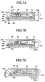
- Fig. 7A shows the crimping device 15
- the crimping device comprises: a crimp plate 62 having a crimp pin 61 which is downward directed; two upper and lower presser plates 65 and 66 respectively having dowel forming holes 63 and 64; a lock plate 67; a press plate 69 having a press pin 68 which is upward directed; and a shifter 70.
- a cam groove is formed in a side face of each of the four plates 62, 65, 66, and 69, and the shifter 70.
- the rear end portions of the four plates 62, 65, 66, and 69 are coaxially coupled to each other by a pin 71.
- the pin 71 is engaged with a long hole 70a of the shifter 70.
- Two front and rear drive pins 72 and 73 which elongate from the shifter 70 pass through the cam grooves of the plates 62, 65, 66, and 69.
- the plates 62, 65, 66, and 69 are vertically swung in accordance with the shapes of their respective cam grooves.
- Fig. 7A In an initial state shown in Fig. 7A, first, the binding piece in the state where the legs are overlapped each other is inserted between the two presser plates 65 and 66.
- the shifter 70 When the shifter 70 is forward moved, the lower presser plate 66 is raised, so that the legs of the binding piece is pressingly fixed by the upper and lower presser plates 65 and 66 as shown in Fig. 7B.
- the press plate 69 is raised as shown in Fig. 7C, so that a dowel is press-formed in each of the legs, by the press pin 68.
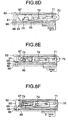
- the lock plate 67 is then forward pushed so that the locking state of the upper presser plate 65 is canceled.
- Fig. 8E therefore, the pressing due to the upper and lower presser plates 65 and 66 is canceled, and the upper presser plate 65 is raised.
- the crimp pin 61 of the crimp plate 62 then crushes the dowel formed by the press pin 68 through the hole 63 of the upper presser plate 65.
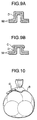
- Fig. 9A shows the shape of a dowel D which is formed by the press pin 68
- Fig. 9B shows the final shape of the dowel D which has undergone the crimping process C by the crimp pin 61
- Fig. 10 shows a state where the binding piece 31 is fastened to the bag B.
- the shifter 70 is retracted to go back to the initial state shown in Fig. 7A, the carrier 25 of the binding device 14 is retracted to return the binding piece guide slider 42, the cover slider 43, and the binding slider 44 to the initial positions shown in Fig. 5.
- the rear end of the carrier 25 pushes the stop switch 27, thereby ending one cycle of the operation.
- the legs of the binding piece 31 are overlapped each ether by laterally pressing the binding piece by the binding arms 48, and the legs are then crimped. As shown in Fig. 10, therefore, the binding piece 31 can be attached to the bag B in close proximity to the contents of the bag, so that the bag B is bound in a tension state.
- the bag which has beer. bound can be opened in the following manner.
- the legs 32 of the binding piece 31 are pulled so as to be separated from each other by fingers.
- the crimped dowel D is deformed, and the legs are separated from each other.
- the binding piece is detached from the bag, so that the bag can be opened.
- the legs 32 of the binding piece 31 are crossed with each other so as to attain the crosswise engaging state of the hooking portion 35.
- the bag cannot be again bound by using the dowel in such a manner that the state before the opening is again attained, because the crimped portion C of the dowel D of the binding piece 31 is deformed. Therefore, the opening history of the bag can be easily checked in a visual manner. This is effective also in safety management and sanitary management during distribution of commodities.
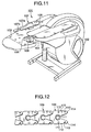
- Fig. 11 shows a bag binder 101.
- the portion on the right side is a binding piece magazine 102 which houses a roll of binding pieces that are linked to one another into a belt-like shape.
- a guide groove 104 is formed in a table 103. which leftward protrudes from the binding piece magazine 102.
- the guide groove has an L-like shape in a plan view, or elongates from a lateral center portion of the front face toward the inner side and is then bent leftward.
- a binding piece feeding device 105 is incorporated on the right side of the guide groove 104, and a binding device 106 on the left side of the guide groove.
- a cutter device 107 is disposed behind the binding device 106.
- an arm 107a which is pivotally mounted to the upper face of the table 103 is swung toward the front side so as to make a guide groove 107b in the front portion coincident with the guide groove 104 of the table 103, an upper extra portion of a bound bag is cut away by a cutter blade (not shown) which can longitudinally slide in the arm 107a with being interlocked with the binding operation.
- the feeding device 105, the binding device 106, and the cutter device 107 are driven by a motor (not shown) via a reduction gear mechanism, and a cam and link mechanism.
- a trigger lever 108 is pivotally mounted to the left side of the guide groove 104.
- a tip end portion of the trigger lever 108 rightward elongates to cross the guide groove 104.
- a binding piece 109 is formed by a resin flat plate having a substantially portal shape.
- a locking pawl portion 111 in the form of internal teeth is disposed in an internal basal portion between right and left legs 110.
- Holes 112 with which pins (described later) of the feeding device 105 are to be engaged are formed in the legs 110, respectively.
- a groove 113 which elongates from the outer side face to the front inner side is formed in the tip end portion of each of the legs, thereby constituting a hooking portion 114.
- a number of binding pieces 109 are integrally molded into a belt-like shape with being aligned in a row. The belt of binding pieces is wound into a roll, and then loaded into the binding piece magazine 102 of the bag binder 101.
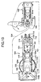
- Fig. 13 shows the arrangement of the feeding device 105 and the binding device 106.
- a carrier 116 is engaged with a carrier guide 115 disposed on the base of the bag binder 101, so as to be longitudinally slidable.
- the carrier 116 is advanced toward the binding device 106, the binding piece 109 is fitted onto the bag, and the binding piece 109 attached to the bag is fastened by the binding device 106.
- a binding piece guide 117 is attached onto the carrier 116 of the feeding device 105 so as to be longitudinally slidable and has upper and lower cases.
- a gap between the upper and lower cases functions as a binding piece passageway in which the center portion is higher (which has an L-like section shape).
- a binding piece table 118 which is similar in shape to the binding piece 109 is formed in a front portion (in the figure, the left portion) of the binding piece guide 117. The binding piece 109 which is forward fed through the binding piece passageway is exposed on the binding piece table 118.
- a pair of right and left C-shape binding arms 119 are coaxially and pivotally mounted to a rear portion of the binding piece table 118.
- the binding arms 119 are coupled via links 121 to an arm shifter 120 which is behind the binding arms 119 and longitudinally slidable.
- a vertical pin 122 protrudes from the tip end portion of each of the binding arms 119.
- the pins 122 are engaged with the holes 112 on the both sides of the binding piece 109 shown in Fig. 12.
- a pin 116a fixed to the carrier 116 is engaged with a groove 120a formed in the arm shifter 120.
- a larger-diameter main gear 123 is disposed below the carrier 116.
- a crank roller 124 disposed in the vicinity of the outer edge of the main gear 123 is engaged with a cam groove 116b formed in the rear portion of the carrier 116.
- the main gear 123 is coupled with the motor via plural reduction gears (not shown).
- a feeding pawl mechanism (not shown) which uses swinging pawls is interposed between the carrier 116 and the binding piece guide 117.
- Feeding pawls which are pivotally mounted to the binding piece guide 117 are engaged with the carrier 116.
- the binding piece guide 117 is pushed by the carrier 116 so as to be advanced together with the carrier 116.
- the guide abuts against a stopper and stops, and the feeding pawls are disengaged from the carrier 116.
- the carrier 116 and the arm shifter 120 are further advanced, so that the pair of right and left binding arms 119 are pushed by the arm shifter 120 and are swung in the closing direction.
- a disk 125 in which a notch 125a is formed is fitted onto the shaft of the main gear 123.
- a light emitting portion and a light receiving portion of a photo-interrupter 126 fixed to a frame (not shown) are vertically opposed to each other across the outer edge portion of the disk 125.
- the photb-interrupter 126 is connected to a motor control unit (not shown). The motor control unit controls the stop position of the carrier 116 in accordance with an output of the photo-interrupter 126.
- the operation of the bag binder 101 will be described.
- the trigger lever 108 is pushed by the bag to swing, and the trigger lever turns on the trigger switch in the table 103 to activate the motor.
- the carrier 116 and the binding piece guide 117 are pushed by the crank roller 124 shown in Fig. 13 so as to be advanced. Since the leading one of the binding pieces 109 is engaged with the pins 122 of the binding arms 119, the leading binding piece is advanced together with the binding piece guide 117 and then fitted onto the puckered portion of the bag. Although illustration is omitted, a cutter which is attached to the upper face of the binding piece guide 117 cuts the portion where the leading binding piece and the next binding piece are linked to each other.
- the feeding pawls of the binding piece guide 117 are disengaged from the carrier 116 and the binding piece guide 117 stops.
- the carrier 116 and the arm shifter 120 are further advanced.
- the pair of right and left binding arms 119 which are pivotally mounted to the binding piece guide 117 are swung in the closing direction, so that the legs of the leading binding piece 109 cross each other.
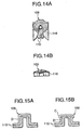
- the binding piece 109 is elastically deformed into a funnel-like shape as shown in Figs. 14A and 14B.
- a press pin of the binding device 106 is positioned directly below the legs 110 of the binding piece 109.
- the binding device 106 is configured in the same manner as that of the first embodiment, and hence its detailed description is omitted.
- a plate from which a punch protrudes, and an upper die plate having a pin hole which serves as a die cooperate to vertically press the legs 110 of the binding piece 109, thereby forming a dowel in the crosswise portions of the legs.
- the dowel is crimped from the upper side by a crimp plate having a crimp pin.
- Fig. 15A shows the shape of a dowel D which is formed by the punch and the die
- Fig. 15B shows the final shape of the dowel D which has undergone the crimping process C by the crimp pin.
- a state where the binding piece 109 is fastened to the bag B is shown in Fig. 10.
- the upper and lower plates of the binding device 106 are then opened to return to their waiting positions, and the carrier 116 is retracted by a predetermined distance. Thereafter, the feeding pawls of the binding piece guide 117 are engaged with the carrier 115, and the binding piece guide 117 is retracted integrally with the carrier 116.
- an ON signal of the photo-interrupter 126 causes a motor control unit to start the braking of the motor or enter the deceleration step.
- the bag which has been bound can be opened in the following manner.
- the legs 110 of the binding piece 109 are pulled so as to be separated from each other by fingers.
- the crimped dowel D is deformed, and the legs are separated from each other.
- the binding piece is detached from the bag, so that the bag can be opened.
- the legs 110 of the binding piece 109 are crossed with each other so as to attain the crosswise engaging state of the locking pawl portion 111 at the tip end.
- the bag cannot be again bound by using the dowel in such a manner that the state before the opening is again attained, because the crimped portion C of the dowel D of the binding piece 109 is deformed. Therefore, the opening history of the bag can be easily checked in a visual manner. This is effective also in safety management and sanitary management during distribution of commodities.
- a flap 127 is pivotally mounted to a front portion of a binding device 106.
- the flap 127 closes the lower open face of the guide groove 104.
- a stopper 127a for restricting the swing of the trigger lever 108 and a sub trigger lever 128 is raised.
- the center portion of the front edge is recessed so as not to impede the insertion of a bag into the guide groove 104.
- the flap 127 is pressingly contacted with the lower face of the table 103 of the bag binder 101 by a tension spring (not shown) elongating between a lug 127b which is raised from the right rear end portion and a frame of the binder.
- a shaft 129 for the trigger lever 108 exposed over a case of the bag binder 101 and the sub trigger lever 128 disposed below the case is positioned in front of the left end portion of the flap 127.
- the trigger lever 108 in the upper side and the sub trigger lever 128 in the case are coupled to each other by a pin 130.
- a pawl 128a is formed in the sub trigger lever 128. In the initial position, the pawl protrudes toward the left edge portion of the flap 127.
- the stopper 127a in the left end of the flap 127 and the pawl 128a of the sub trigger lever 128 constitute a safety device.
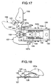
- the trigger lever 108 and the sub trigger lever 128 are swung from the initial positions shown in Fig. 17 in a counterclockwise direction, the pin 130 pushes a lever of a trigger switch 131 to activate the bag binder 101.
- the sub trigger lever 128 is displaced with respect to the trigger lever 108 by about 90 degree in a clockwise direction in the figure.
- the bag pushes the trigger lever 108, the bag is inserted into the guide groove 104 with being sandwiched between the trigger lever 108 and the sub trigger lever 128, and then pushed by the sub trigger lever 128 so as to be surely inserted into the binding piece feeding passageway.
- the trigger lever 108 and the sub trigger lever 128 are returned to the initial positions by a spring (not shown).
- the lower end of the front portion of the semicircular stopper 127a of the flap 127 is removed away so as not to interfere with the pawl 128a of the sub trigger lever 128.
- the trigger lever 108 and the sub trigger lever 128 can be freely swung.
- the stopper 127a advances into the radius of rotation of the pawl 128a of the sub trigger lever 128.
- the pawl 128a bumps against the stopper 127a to block the swinging operations of the trigger lever 108 and the sub trigger lever 128.
- the flap 127 is opened, therefore, the trigger lever cannot be swung, thereby attaining the safety in the case such as that where the flap 127 is opened and a binding piece jammed in the binding device 106 is to be removed away.
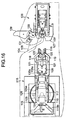
- the binding device 106 is configured in the same manner as that of the first embodiment, and hence its detailed description is omitted.
- a base plate 132 is fixed to the lower portion of a frame 106a of the binding device.
- a lower release plate 133, a center die plate 134, and an upper press plate 135 are pivotally mounted to a stationary shaft 106b which is disposed above the base plate.
- the three plates 133, 134, and 135 are lowered or raised by a shifter 136 which is longitudinally moved.
- the base plate 132 from which a punch is raised, and the die plate 134 which is above the base plate and in which a pin hole serving as a die is formed cooperate to vertically press the crosswise portions of the legs of the binding piece 109, thereby forming a dowel.
- the dowel is crimped from the side above the pin hole by a crimp pin of the press plate 135 which is above the die plate 134.
- the binding piece 109 is pulled out from the punch of the base plate
- the carrier 116 and the binding piece guide 117 are pushed by the crank roller 124 shown in Fig. 16 so as to be advanced. Since the leading one of the coupled binding pieces 109 is engaged with the pins 122 of the binding arms 119, the leading binding piece is advanced together with the binding piece guide 117 and then fitted onto the puckered portion of the bag. Although illustration is omitted, a cutter which is attached to the upper face of the binding piece guide 117 cuts the portion where the leading binding piece and the next binding piece are linked to each other.
- the feeding pawls of the binding piece guide 117. are disengaged from the carrier 116 and the binding piece guide 117 stops.
- the carrier 116 and the arm shifter 120 are further advanced.
- the pair of right and left binding arms 119 which are pivotally mounted to the binding piece guide 117 are swung in the closing direction, so that the legs of the leading binding piece 109 cross each other.
- the binding piece 109 is elastically deformed into a dome-like shape.
- the legs of the binding piece 109 enter the space between the die plate 134 and the release plate 133 of the binding device 106.
- the binding device 106 crimps the binding piece 109 to fasten it.
- the feeding device 105 performs the returning step.
- the carrier 116 is retracted by a predetermined distance
- the feeding pawls of the binding piece guide 117 are engaged with the carrier 115, and the binding piece guide 117 is retracted integrally with the carrier 116.
- the combination of the disk 125 and the photo-interrupter 126 detects that the guide reaches the waiting position, and the guide stops at the waiting position shown in Fig. 16.
- the worker pulls down the bag. Then, the bag is pulled out to a space below the table 103 of the bag binder 101.
- Fig. 10 shows a state where the binding piece 109 is fastened to the bag B.
- the flap 127 in the lower face of the table 103 is downward opened, and the binding piece 109 remaining in the binding device 106 is removed away.
- the stopper 127a of the flap 127 blocks the swinging operations of the trigger levers 108 and 128. Even if the worker erroneously touches the trigger lever 108, therefore, the lever is not swung to the activating position, and hence the binding piece can be safely removed away.
- the binding piece when an accident such as that a binding piece cannot be removed from the punch of the binding device or that a binding piece is jammed in the press-bonding device by any reason occurs, the binding piece must be removed away while opening the flap disposed in a portion where the binding device is incorporated.
- the motor When the worker touches the trigger lever in the vicinity of the press-bonding device during the work of removing the binding piece, the motor is activated, thereby producing a fear that a finger is squeezed by the feeding device and the binding device or that a finger is damaged by the cutter device for cutting an upper extra portion of the bag. According to the third embodiment, such a fear can be eliminated.
- the bag binder attaches a binding piece to a puckered portion of a bag by pressing the outer side of the legs of the binding piece.
- a binding piece can be attached to a bag in close proximity to contents of the bag, so that the bag is bound in a tension state. Consequently, damages due to abrasion between contents of a bag can be prevented from occurring, and a bag containing commodities can be easily handled.
- the invention is preferably applied to packing of commodities which are readily damaged, such as vegetables, or fruits.
- the rotation position of the main gear for driving the binding mechanism is detected by the photo-sensor, and the stop position is controlled in accordance with a signal of the photo-sensor. Therefore, the accuracy of the control of the waiting position is improved, and the invention can attain an effect in stabilization of the binding operation.
- the trigger lever in the case such as that where a binding piece jammed in the bag binder is to be removed away, when the flap covering the binding mechanism is opened, the trigger lever cannot be swung. Therefore, an accident caused by an erroneous operation of the trigger lever can be prevented from occurring, and hence the safety is improved.
Landscapes
- Engineering & Computer Science (AREA)
- Mechanical Engineering (AREA)
- Package Closures (AREA)
Claims (10)
- Machine de liage (11; 101) pour lier un sac, comprenant :dans lequel ledit mécanisme régulateur comprend ;un organe d'alimentation en élément de ligaturage (14; 105) pour fournir un élément de ligaturage (31; 109) en une position adjacente dudit sac, ledit élément de ligaturage (31; 109) réalisé en résine synthétique étant réalisé et comprenant une paire de parties patte (32; 110) pour lier ledit sac ;un organe de croisement pour croiser lesdites parties patte (32; 110) par pressage desdites parties patte dudit élément de lien (31; 109) ;un organe de mise en prise, pour mettre en prise lesdites parties pattes (32; 110) desdits éléments de lien (31; 109) l'un l'autre pour mettre en prise de façon croisée une partie croisée desdites parties patte (32; 110), caractérisée parun mécanisme régulateur, pour commander une opération de ligaturage à l'aide de l'organe d'alimentation en élément de ligaturage (14; 105), dudit organe de croisement et dudit élément de mise en prise ;un mécanisme principal (23; 123) entraíné par un moteur, dont la rotation effectue un cycle de ladite opération de ligaturage ;un disque (125) fixé coaxialement sur ledit mécanisme principal (23; 123), ledit disque (125) comprenant une partie d'indexation (125a) prévue sur une partie de bordure dudit disque (125) ; etun photo-capteur (126) détectant ladite partie d'indexation (125a) pour détecter un cycle de ladite opération de ligaturage.
- Machine de liage selon la revendication 1, dans laquelle ledit photo-capteur (126) envoie un parmi un signal de mise en service et un signal de mise hors service selon le résultat souhaité de la détection de ladite partie d'indexation (125a) avec ledit photo-capteur (126).
- Machine de liage selon l'une des revendications 1 à 2,
dans laquelle ledit moteur entraíne un système d'entraínement pour entraíner au moins l'un desdits organes d'alimentation d'éléments de ligaturage (14; 105), ledit organe de croisement, ledit organe de mise en prise, ledit mécanisme principal (23; 123) et ledit disque (125) ; et
dans lequel le freinage dudit système d'entraínement commence lorsque ledit résultat détecté change, passant dudit signal de mise en service ou dudit signal de mise hors service à l'autre signal durant ladite opération de ligaturage. - Machine de liage selon la revendication 3, dans laquelle ledit moteur est stoppé lorsque ledit résultat détecté change, passant d'un parmi ledit signal de mise en service et ledit signal de mise hors service à l'autre signal après le commencement du freinage dudit système d'entraínement
- Machine de liage selon l'une des revendications 1 à 4, dans laquelle ladite partie d'indexation (125a) est choisie parmi une encoche et un miroir.
- Machine de liage selon l'une des revendications 1 à 5, caractérisée parun levier de déclenchement (108) qui lance un cycle d'une opération de ligaturage à l'aide dudit organe d'alimentation en élément de ligaturage (14; 105), dudit organe de croisement, dudit organe de mise en prise ; etun couvercle rabattable (127) prévu sur ledit dispositif de ligaturage (106) ledit couvercle rabattable (127) comprenant une butée (127a) pour restreindre la rotation dudit levier de déclenchement (108).
- Machine de liage selon la revendication 6, dans laquelle ladite butée (127) limite ladite rotation dudit levier de déclenchement (108) du fait que ladite butée (127a) est en saillie sur une trajectoire de rotation dudit levier de déclenchement (108) lorsque ledit couvercle rabattable (127) est couvert, dans lequel ladite butée (127a) soit écartée de ladite trajectoire de rotation dudit levier de déclenchement (108) tandis que ledit couvercle rabattable (127) est fermé.
- Machine de liage selon l'une des revendications 1 à 7, dans laquelle ledit organe de mise en prise comprend l'un d'un organe de liage parmi un organe de liaison par pressage et un organe de liaison par fusion.
- Machine de liage selon la revendication 8, dans laquelle ledit organe de liaison par pressage comprend un organe de formage (61) pour former une partie cheville (D) sur ladite partie croisée desdites parties patte (32; 110) et un dispositif de pliage (15) pour plier lesdites parties de cheville (D).
- Machine de liage selon l'une des revendications 1 à 9, dans laquelle ledit organe de croisement comprend une paire de bras de liaison (48; 119) placés sur une partie adjacente à un bout dudit dispositif d'alimentation en élément de ligaturage (14; 105).
Applications Claiming Priority (4)
| Application Number | Priority Date | Filing Date | Title |
|---|---|---|---|
| JP3332298A JPH11227721A (ja) | 1998-02-16 | 1998-02-16 | 袋結束機の待機位置制御装置 |
| JP3332298 | 1998-02-16 | ||
| JP8182698 | 1998-03-27 | ||
| JP08182698A JP3489433B2 (ja) | 1998-03-27 | 1998-03-27 | 袋結束機の安全装置 |
Publications (2)
| Publication Number | Publication Date |
|---|---|
| EP0936147A1 EP0936147A1 (fr) | 1999-08-18 |
| EP0936147B1 true EP0936147B1 (fr) | 2003-05-28 |
Family
ID=26372001
Family Applications (1)
| Application Number | Title | Priority Date | Filing Date |
|---|---|---|---|
| EP99102991A Expired - Fee Related EP0936147B1 (fr) | 1998-02-16 | 1999-02-15 | Machine de liage |
Country Status (3)
| Country | Link |
|---|---|
| US (1) | US6098370A (fr) |
| EP (1) | EP0936147B1 (fr) |
| DE (1) | DE69908196T2 (fr) |
Families Citing this family (11)
| Publication number | Priority date | Publication date | Assignee | Title |
|---|---|---|---|---|
| JP3674395B2 (ja) | 1999-07-13 | 2005-07-20 | マックス株式会社 | 結束用クリップ |
| JP3480378B2 (ja) * | 1999-07-28 | 2003-12-15 | マックス株式会社 | 手動式袋結束機 |
| JP2001130515A (ja) * | 1999-11-09 | 2001-05-15 | Max Co Ltd | 袋結束機 |
| DE20217038U1 (de) * | 2002-11-05 | 2003-03-27 | Georg Hartmann Maschb Gmbh | Beutelverschließvorrichtung |
| NL1024491C2 (nl) * | 2003-10-09 | 2005-04-12 | Schutte Holding B V | Werkwijze voor het sluiten van een flexibele verpakking, een inrichting daarvoor en een gesloten flexibele verpakking. |
| US7596928B2 (en) * | 2004-11-02 | 2009-10-06 | Irwin Jere F | Apparatus for severing and loading bag fasteners |
| US8261513B2 (en) * | 2004-11-02 | 2012-09-11 | Irwin Jere F | Apparatus and method for severing and loading bag fasteners |
| DE102006002291B4 (de) * | 2006-01-18 | 2023-06-29 | Rovema Gmbh | Vorrichtung zum Spenden von Abschnitten eines Bandes |
| USD880296S1 (en) | 2018-09-25 | 2020-04-07 | Klr Systems Inc. | Bag closure clip |
| USD871212S1 (en) | 2018-09-25 | 2019-12-31 | Klr Systems Inc. | Bag closure clip |
| CN113177925B (zh) * | 2021-05-11 | 2022-11-11 | 昆明理工大学 | 一种无损检测水果表面缺陷的方法 |
Family Cites Families (5)
| Publication number | Priority date | Publication date | Assignee | Title |
|---|---|---|---|---|
| US3668818A (en) * | 1971-02-08 | 1972-06-13 | Kwik Lok | Semi-automatic closure applicator |
| GB1446012A (en) * | 1973-07-05 | 1976-08-11 | Britt J P | Packaging |
| US3910811A (en) * | 1974-07-18 | 1975-10-07 | Kwik Lok | Method and machine for removeably securing stiff plastic closures flat against series of moving packages |
| US5269120A (en) * | 1990-09-17 | 1993-12-14 | Kwik Lok Corporation | System for marking and installing closures |
| US5485711A (en) * | 1993-08-20 | 1996-01-23 | Max Co., Ltd. | Binding machine |
-
1999
- 1999-02-15 DE DE69908196T patent/DE69908196T2/de not_active Expired - Fee Related
- 1999-02-15 EP EP99102991A patent/EP0936147B1/fr not_active Expired - Fee Related
- 1999-02-16 US US09/249,779 patent/US6098370A/en not_active Expired - Fee Related
Also Published As
| Publication number | Publication date |
|---|---|
| DE69908196D1 (de) | 2003-07-03 |
| US6098370A (en) | 2000-08-08 |
| DE69908196T2 (de) | 2003-11-27 |
| EP0936147A1 (fr) | 1999-08-18 |
Similar Documents
| Publication | Publication Date | Title |
|---|---|---|
| EP0936147B1 (fr) | Machine de liage | |
| CA1306179C (fr) | Tete pour machine a cercler sans laisser de joint | |
| JP2004189341A (ja) | トラック内に配置された物品を結束するための装置 | |
| US4265014A (en) | Apparatus for press-bonding a reinforced tape to a slide fastener with a separable end stop | |
| US3450028A (en) | Strapping apparatus | |
| CA1133240A (fr) | Dispositif pour garnir une paire de bandes de fermetures a glissiere avec une pellicule de renforcement | |
| US3215064A (en) | Automatic strapping and sealing machine | |
| JPH0128563B2 (fr) | ||
| EP0089002B1 (fr) | Méthode et appareil pour fixer automatiquement des butées d'extrémité supérieures sur une chaîne de fermeture à glissière munie d'intervalles dépourvus d'éléments d'accouplement et sur laquelle sont montés des curseurs | |
| US3771707A (en) | Binding device | |
| JP3489433B2 (ja) | 袋結束機の安全装置 | |
| JP4032484B2 (ja) | 袋結束機の結束具圧着装置 | |
| US20070062246A1 (en) | Crimping Press | |
| US4494292A (en) | Method for securing bottom end stop to fastener chain | |
| JP3147006B2 (ja) | 袋結束機及び袋を結縛する結束方法 | |
| JPH11227721A (ja) | 袋結束機の待機位置制御装置 | |
| US3746236A (en) | Bottom stop machine | |
| EP1099635A2 (fr) | Appareil pour encercler des cols de sachets | |
| JP3211550B2 (ja) | 結束機における結束具の供給、切断機構 | |
| US2845626A (en) | Stapling apparatus | |
| US1939123A (en) | Tightening and closing device | |
| JPH11227722A (ja) | 袋結束機の起動制御装置 | |
| JPS589799A (ja) | プレス機械の安全装置 | |
| US2862527A (en) | Machine for binding parcels | |
| EP0840409B1 (fr) | Appareil de sertissage portable motorisé |
Legal Events
| Date | Code | Title | Description |
|---|---|---|---|
| PUAI | Public reference made under article 153(3) epc to a published international application that has entered the european phase |
Free format text: ORIGINAL CODE: 0009012 |
|
| AK | Designated contracting states |
Kind code of ref document: A1 Designated state(s): DE FR GB |
|
| AX | Request for extension of the european patent |
Free format text: AL;LT;LV;MK;RO;SI |
|
| 17P | Request for examination filed |
Effective date: 19991223 |
|
| AKX | Designation fees paid |
Free format text: DE FR GB |
|
| 17Q | First examination report despatched |
Effective date: 20010731 |
|
| GRAH | Despatch of communication of intention to grant a patent |
Free format text: ORIGINAL CODE: EPIDOS IGRA |
|
| GRAH | Despatch of communication of intention to grant a patent |
Free format text: ORIGINAL CODE: EPIDOS IGRA |
|
| GRAH | Despatch of communication of intention to grant a patent |
Free format text: ORIGINAL CODE: EPIDOS IGRA |
|
| GRAA | (expected) grant |
Free format text: ORIGINAL CODE: 0009210 |
|
| AK | Designated contracting states |
Designated state(s): DE FR GB |
|
| REG | Reference to a national code |
Ref country code: GB Ref legal event code: FG4D |
|
| REF | Corresponds to: |
Ref document number: 69908196 Country of ref document: DE Date of ref document: 20030703 Kind code of ref document: P |
|
| PG25 | Lapsed in a contracting state [announced via postgrant information from national office to epo] |
Ref country code: GB Free format text: LAPSE BECAUSE OF NON-PAYMENT OF DUE FEES Effective date: 20040215 |
|
| ET | Fr: translation filed | ||
| PLBE | No opposition filed within time limit |
Free format text: ORIGINAL CODE: 0009261 |
|
| STAA | Information on the status of an ep patent application or granted ep patent |
Free format text: STATUS: NO OPPOSITION FILED WITHIN TIME LIMIT |
|
| 26N | No opposition filed |
Effective date: 20040302 |
|
| PG25 | Lapsed in a contracting state [announced via postgrant information from national office to epo] |
Ref country code: DE Free format text: LAPSE BECAUSE OF NON-PAYMENT OF DUE FEES Effective date: 20040901 |
|
| GBPC | Gb: european patent ceased through non-payment of renewal fee |
Effective date: 20040215 |
|
| PG25 | Lapsed in a contracting state [announced via postgrant information from national office to epo] |
Ref country code: FR Free format text: LAPSE BECAUSE OF NON-PAYMENT OF DUE FEES Effective date: 20041029 |
|
| REG | Reference to a national code |
Ref country code: FR Ref legal event code: ST |