EP0930902B1 - Druckbehälter zum beaufschlagen eines in diesem aufgenommenen, mit einer medizinischen flüssigkeit gefüllten flexiblen beutels mit druck - Google Patents
Druckbehälter zum beaufschlagen eines in diesem aufgenommenen, mit einer medizinischen flüssigkeit gefüllten flexiblen beutels mit druck Download PDFInfo
- Publication number
- EP0930902B1 EP0930902B1 EP98943819A EP98943819A EP0930902B1 EP 0930902 B1 EP0930902 B1 EP 0930902B1 EP 98943819 A EP98943819 A EP 98943819A EP 98943819 A EP98943819 A EP 98943819A EP 0930902 B1 EP0930902 B1 EP 0930902B1
- Authority
- EP
- European Patent Office
- Prior art keywords
- pressure container
- housing
- cover
- bag
- anyone
- Prior art date
- Legal status (The legal status is an assumption and is not a legal conclusion. Google has not performed a legal analysis and makes no representation as to the accuracy of the status listed.)
- Expired - Lifetime
Links
Images





Classifications
-
- A—HUMAN NECESSITIES
- A61—MEDICAL OR VETERINARY SCIENCE; HYGIENE
- A61M—DEVICES FOR INTRODUCING MEDIA INTO, OR ONTO, THE BODY; DEVICES FOR TRANSDUCING BODY MEDIA OR FOR TAKING MEDIA FROM THE BODY; DEVICES FOR PRODUCING OR ENDING SLEEP OR STUPOR
- A61M3/00—Medical syringes, e.g. enemata; Irrigators
- A61M3/02—Enemata; Irrigators
- A61M3/0233—Enemata; Irrigators characterised by liquid supply means, e.g. from pressurised reservoirs
-
- A—HUMAN NECESSITIES
- A61—MEDICAL OR VETERINARY SCIENCE; HYGIENE
- A61M—DEVICES FOR INTRODUCING MEDIA INTO, OR ONTO, THE BODY; DEVICES FOR TRANSDUCING BODY MEDIA OR FOR TAKING MEDIA FROM THE BODY; DEVICES FOR PRODUCING OR ENDING SLEEP OR STUPOR
- A61M3/00—Medical syringes, e.g. enemata; Irrigators
- A61M3/02—Enemata; Irrigators
- A61M3/0233—Enemata; Irrigators characterised by liquid supply means, e.g. from pressurised reservoirs
- A61M3/0245—Containers therefor, e.g. with heating means or with storage means for cannula
-
- A—HUMAN NECESSITIES
- A61—MEDICAL OR VETERINARY SCIENCE; HYGIENE
- A61M—DEVICES FOR INTRODUCING MEDIA INTO, OR ONTO, THE BODY; DEVICES FOR TRANSDUCING BODY MEDIA OR FOR TAKING MEDIA FROM THE BODY; DEVICES FOR PRODUCING OR ENDING SLEEP OR STUPOR
- A61M3/00—Medical syringes, e.g. enemata; Irrigators
- A61M3/02—Enemata; Irrigators
- A61M3/0233—Enemata; Irrigators characterised by liquid supply means, e.g. from pressurised reservoirs
- A61M3/0254—Enemata; Irrigators characterised by liquid supply means, e.g. from pressurised reservoirs the liquid being pumped
-
- A—HUMAN NECESSITIES
- A61—MEDICAL OR VETERINARY SCIENCE; HYGIENE
- A61M—DEVICES FOR INTRODUCING MEDIA INTO, OR ONTO, THE BODY; DEVICES FOR TRANSDUCING BODY MEDIA OR FOR TAKING MEDIA FROM THE BODY; DEVICES FOR PRODUCING OR ENDING SLEEP OR STUPOR
- A61M5/00—Devices for bringing media into the body in a subcutaneous, intra-vascular or intramuscular way; Accessories therefor, e.g. filling or cleaning devices, arm-rests
- A61M5/14—Infusion devices, e.g. infusing by gravity; Blood infusion; Accessories therefor
- A61M5/1414—Hanging-up devices
- A61M5/1417—Holders or handles for hanging up infusion containers
-
- A—HUMAN NECESSITIES
- A61—MEDICAL OR VETERINARY SCIENCE; HYGIENE
- A61M—DEVICES FOR INTRODUCING MEDIA INTO, OR ONTO, THE BODY; DEVICES FOR TRANSDUCING BODY MEDIA OR FOR TAKING MEDIA FROM THE BODY; DEVICES FOR PRODUCING OR ENDING SLEEP OR STUPOR
- A61M5/00—Devices for bringing media into the body in a subcutaneous, intra-vascular or intramuscular way; Accessories therefor, e.g. filling or cleaning devices, arm-rests
- A61M5/14—Infusion devices, e.g. infusing by gravity; Blood infusion; Accessories therefor
- A61M5/142—Pressure infusion, e.g. using pumps
- A61M5/145—Pressure infusion, e.g. using pumps using pressurised reservoirs, e.g. pressurised by means of pistons
- A61M5/148—Pressure infusion, e.g. using pumps using pressurised reservoirs, e.g. pressurised by means of pistons flexible, e.g. independent bags
- A61M5/1483—Pressure infusion, e.g. using pumps using pressurised reservoirs, e.g. pressurised by means of pistons flexible, e.g. independent bags using flexible bags externally pressurised by fluid pressure
- A61M5/1486—Pressure infusion, e.g. using pumps using pressurised reservoirs, e.g. pressurised by means of pistons flexible, e.g. independent bags using flexible bags externally pressurised by fluid pressure the bags being substantially completely surrounded by fluid
-
- A—HUMAN NECESSITIES
- A61—MEDICAL OR VETERINARY SCIENCE; HYGIENE
- A61M—DEVICES FOR INTRODUCING MEDIA INTO, OR ONTO, THE BODY; DEVICES FOR TRANSDUCING BODY MEDIA OR FOR TAKING MEDIA FROM THE BODY; DEVICES FOR PRODUCING OR ENDING SLEEP OR STUPOR
- A61M3/00—Medical syringes, e.g. enemata; Irrigators
- A61M3/02—Enemata; Irrigators
- A61M3/0204—Physical characteristics of the irrigation fluid, e.g. conductivity or turbidity
- A61M3/0208—Physical characteristics of the irrigation fluid, e.g. conductivity or turbidity before use
-
- A—HUMAN NECESSITIES
- A61—MEDICAL OR VETERINARY SCIENCE; HYGIENE
- A61M—DEVICES FOR INTRODUCING MEDIA INTO, OR ONTO, THE BODY; DEVICES FOR TRANSDUCING BODY MEDIA OR FOR TAKING MEDIA FROM THE BODY; DEVICES FOR PRODUCING OR ENDING SLEEP OR STUPOR
- A61M3/00—Medical syringes, e.g. enemata; Irrigators
- A61M3/02—Enemata; Irrigators
- A61M3/0204—Physical characteristics of the irrigation fluid, e.g. conductivity or turbidity
- A61M3/022—Volume; Flow rate
Definitions
- the invention relates to a pressurized container one in it, with a medical fluid filled flexible bag with pressure to keep liquid out dispense the flexible bag, with a housing that one Has opening for inserting the bag, with a lid to cover the opening, with an opening to discharge one Liquid discharge line of the bag from the pressure container, and with a closure for sealingly connecting Cover and housing.
- Such a pressure vessel is known from DE 41 37 748 A1.
- the housing With large amounts of liquid, there are bags up to 5 l in use, the housing must then have a corresponding size and need not only withstand the usual pressures during handling, so about 1 - 1.5 bar, but must be based on approval regulations withstand a test pressure of approx. 4.5 bar.
- the handling is extreme with the pressure vessel mentioned at the beginning cumbersome, and due to the cuboid geometry are corresponding elaborate connection or weld seams provided along the rectangular edges. Especially with large ones The apparatus builds pressure vessels very bulky and is very heavy.
- the object is achieved in that the housing as standing, closed at the bottom, open at the top hollow cylindrical body is formed, the cross section is flat oval and roughly the cross-sectional contour of a bag corresponds, and that the two opposite large-area, standing side walls, each mirroring the Have shape of a portion of a cylinder jacket, the lateral ends are connected via connecting sections.
- the shape of the bag can be light, slim adapted, easy-to-use pressure vessels are created. Because of their lightness, the pressure vessels can, for example also on tripods used in the medical field of liquids are used. After the bag is simply inserted through the oval top opening was supplied and then the liquid drain line the container only needs to be closed with the lid and be tightly connected via the closure. Also this measure is simple and safe even from untrained Personnel. By applying pressure can then the liquid from the bag is targeted, i.e. in the desired one Quantity per unit of time.
- the lid as a covering the oval upper opening and the upper edge spanned lid.
- This measure has the advantage that this geometry is simple and secure placement of the lid on the housing Introducing the bag opened, so that even technically untrained Personnel the lid into the appropriate closed position can bring to the tight connection then over the closure manufacture.
- the pane at least in a side window provided a window, also has the shape of a cylinder jacket section, and the washer is on the inside of the case Viewing window created.
- This measure is particularly useful for very large pressure vessels with large windows the advantage that through the material web to the wall in which the window is provided is stable remains and secondly for the window created on the inside an additional support point is provided so that, for example Window materials made of transparent plastic can be used.
- the closure has at least one arranged on the outside of the housing Turn the knob on, on the inside of which is a slide guide is recessed into which a link pin projecting radially from the cover is insertable, and by turning the rotary knob the backdrop prevents the cover from being removed from the housing.
- the link pin a cylindrical protruding radially from the cover Shoulder section, on which a roller The end follows, the backdrop guide being designed in such a way that they are in a first section of the roll over a ramp runs and only in the end position an end section with stop comes to rest on the shoulder section.
- the backdrop guide undercut in the area of the stop.
- top edge of the body and the lid have a circumferential V-seal intended.
- This measure has the advantage that it creates a kind of self-sealing mechanism is created because with increasing contact pressure the seal between the casing and casing Lid enlarged due to the V-geometry.
- two are on the Connection sections of the cylinder jacket walls arranged, diametrically opposed closures are provided.
- This measure has the advantage that diametrically through the two opposite closures of the oval lid evenly can be locked.
- a connection for the supply of a pressure medium in the pressure vessel provided at least in the lid.
- This measure has the advantage that such pressure supply lines handling when inserting and removing the bag from the Do not disturb the housing and then when putting on and closing the Cover also automatically feeds the print medium provided.
- the inner wall of the housing with a sliding coating.
- the bags are mostly made of plastic materials, and that Material of the pressure vessel will mostly be metal, so must two materials slide past each other because of their different material structure not particularly well together slide.
- the sliding surface for example made of a smooth Teflon material or the like the bag gently into the case.
- the entire Pressure vessel can be attached to a tripod.
- the housing via a device that can be extended and retracted along the tripod axis captively connected to the lid.
- This measure has the advantage that when handling or if necessary a later cleaning process not accidentally the lid can be relocated, but these two essential components captively connected are. Thanks to the device that can be extended and retracted along the tripod axis can the housing relative to the lid or vice versa be moved, for example to remove an empty bag and fill a full bag. This makes it easier continue to use simple measures.
- the device telescopic.
- This measure has the advantage that lean, along the Tripod axis extending telescopes can be used that do not require large installation space and do not require handling the unwanted bulky components of the pressure vessel.
- the cover is firmly connected to the tripod, and the housing is opposite the cover can be moved along the tripod axis.
- a relief spring is provided that the travel process of the housing relieved.
- the spring is a Gas spring, a scroll spring or a spring with a memory alloy.
- the lid is provided with a hanging device for the bag.
- a molded seal can be used, into which the liquid discharge line is insertable.
- the molded seal can either be on the Liquid discharge line may be provided or before insertion be pushed onto this.
- a covers the Upper edge of the housing overlapping section of the cover also partially the molded seal.
- This measure has the advantage that it is particularly reliable this point can be sealed as by the inside prevailing pressure the form seal from the inside to the overlapping section is pressed tightly.
- the Form seal the housing wall in the area of the recess inside and outside.
- This measure has the advantage that such a molded seal is simply insertable into the recess from above and also is relatively large area around the recess, thus for one provides excellent sealing.
- the molded seal slotted so that the liquid discharge line in the molded seal can be pressed in.
- This measure has the considerable advantage that the pressure vessel bag kept warm or warmed if necessary can be.
- a is on the cover Basket attached, in which the bag can be inserted.
- This measure has the advantage that the flexible bags in Basket held in position and supported, so that in particular with large bags can be prevented that a large Contact between the bag and the inner wall of the housing takes place.
- This will not only insert or insert the bag inside the pressure vessel is essential relieved, but it is also easily possible to mistake one inserted bag, which is still full, again from the pressure vessel.
- the windows that close the viewing openings attached from the inside there is a risk that the bag gets caught in the windows.
- a large bag for example with a content of 5 l or two
- a bag with 1.5 l is inserted into the pressure vessel this is made much easier by the basket.
- Very big and when stored, heavy bags take the form of a very wide drop, so that then possibly large-area contact could take place with the inner chamber wall. This is now going through prevented the basket safely.
- the basket has a floor that is spaced above the closed floor of the housing comes to rest.
- the liquid drain line extends from the bottom of the bag away and must go through a 180 ° loop from the bottom of the bag be guided to the upper edge of the pressure vessel. If the Bottom of the bag on the bottom of the housing of the pressure vessel to lie, the line could bend and the drainage of the Lock liquid. Now the bag can be placed on the bottom of the Basket are stored and there is still enough under the floor Space available to properly strap the loop to lead.
- the basket has a guide for the liquid discharge line of the bag.
- the guide Hook into which the liquid discharge line can be inserted.
- This measure has the advantage that the line is very simple the hooks can be inserted, inserted or threaded and by appropriate shaping and alignment of the hooks is also fixed.
- the floor is made from a serpentine winding rod body.
- the heater formed as a wall of the basket.
- This measure now has the advantage that the controls that connected to the heater, attached to a component are, namely on the lid to which the basket is attached is, the wall is designed as a heater, so that a easy handling and a simple design of this Components is possible.
- 1 is a reference number 10 in its entirety provided pressure vessel shown.
- the pressure vessel 10 has a housing 12 and one of them separable cover 14.
- the housing 12 consists of a standing, approximately hollow cylindrical Body 16, which is closed on the bottom side by a bottom 18 is.
- the housing 12 has two opposite, mirror images arranged side walls 20, 22, which over connecting sections 24 and 26 are interconnected.
- the side walls 20 and 22 have the shape of a cylinder jacket section.
- a recess 30 is provided, the purpose of which will be described later becomes.
- the cover 14 is attached to a tripod 32 via a fastening 40 releasably attached.
- a fastening 40 releasably attached.
- Attachment device 34 is provided, in which a bag 36 is suspended can be.
- the bag 36 is made of a flexible plastic material and is with a medical not specified here Liquid filled. At the bottom of the bag 36 leads one firmly connected to this liquid discharge line 38, and in the form of a hose welded to the bag 36.
- a connecting piece 41 which has a Line can be connected to a pressure source 42. Further is a pressure relief valve 43 is provided on the cover.
- a window 48 is provided, which by a inside disc 49 is closed.
- a heater not shown here, in the form a flat heating mat provided to the contained in the bag 36 Either keep liquid warm (e.g. at 37 ° or 42 ° C) or to heat if necessary.
- the handling of the pressure container 10 is as follows. To insert a bag 36 filled with a liquid will Housing 12 lowered, i.e. along the stand 32 down postponed. Then 14 is on the underside of the lid the bag 36 hanged. Then the housing 12 from below pushed over the bag 36 hanging on the lid 14. The operator detects the liquid discharge line 38 with a Hand and ensures that this from above in the recess 30th comes to rest. The housing 12 is pushed until the top edge 28 of which lies on the underside of the cover 14 comes. For this purpose, an oval-shaped V seal, not shown here, is used placed between housing 12 and cover 14.
- the lid 14 has a downwardly projecting, overlapping section 46 on, which is designed so that it also partially the recess 30 covers, so that then a tight discharge the liquid discharge line 38 can be accomplished, like that later in connection with other exemplary embodiments will be described in more detail.
- a gaseous pressure medium for example compressed air or CO 2
- a pressure can gradually be built up.
- This pressure ensures that the bag 36 is squeezed together and the liquid contained therein is discharged from the pressure vessel 10 via the liquid discharge line 38, as is indicated by an arrow 39.
- the respective fill level of the bag 36 can be followed via the window 48. If the bag 36 is emptied or the rinsing process is ended, the interior is vented to atmospheric pressure, the closure (not shown) is opened, and the housing 12 can be lowered again, so that the now empty bag 36 can be removed and a new one inserted.
- liquid discharge line 38 By passing the liquid discharge line 38 over the recess 30 does not need the liquid discharge line 38 be threaded through a hole, for example in the floor, so that then the liquid discharge line provided by the manufacturer 38 directly, without the interposition of a connecting line or lead-through, for example to the instrument that the rinsing liquid is to be supplied can be.
- the pressure vessel shown in Figures 2 to 10 is in in its entirety provided with the reference number 50.
- the pressure container 50 also has, as described above, a housing 52 and a cover 54.
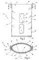
- the housing 52 has, as shown in particular in the illustrations 2 and 3 can be seen, a standing, on lower end closed by a bottom 58, open at the top hollow cylindrical body 56.
- the body 56 has two mirror images, outwardly curved side walls 60 and 62 which flattened over Connection sections 64 and 66 connected to each other are.
- Fig. 3 is indicated by a radius 63 that the Side wall 62 as a section of a cylinder jacket with the radius 63 is formed. The same applies to the side wall 60.
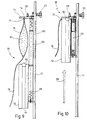
- a recess 70 provided to carry out the liquid discharge line 78 serves. From Fig. 9 it can be seen that the cover 54 over a mounting 124 is attached to a tripod 72.
- a hanging device 74 is provided, to which a bag 76 is attached can.
- a liquid discharge line leads from the bag 76 78 in the form of a hose.
- a transparent plastic material is a medical one Liquid 80 added.
- a pressure valve can be arranged, so that, for example in the position shown in Fig. 9, no liquid flows out through gravity, but that a certain pressure must be exceeded.
- a window 82 is provided which is transparent Disc 84 is closed.
- the Disc 84 is applied to the inner wall 85 in the area of the window 82 and also has the shape of a cylinder jacket section on.
- the window 82 is a horizontal one Material web 86 in two approximately equal sections divided up. The web 86 not only increases the stability of the Sidewall 60 but also provides additional support the disk 84 against bulging or bulging.
- the inner wall 85 of the entire housing 52 is with a sliding coating 87 provided, for example a coating with Teflon.
- V-seal 88 On the upper edge 68 there is a circumferential V-seal 88, such as this in particular from the enlarged sectional views of 4 and 5 can be seen.
- the V-seal 88 thus also covers the recess 70 in FIG Top edge 68.
- a molded seal 90 is additionally inserted into the recess 70, like that also from the sectional representations of FIG. 4 and 5 can be seen.
- the molded seal 90 has a substantially U-shaped body on, which are inserted into the recess 70 from above can.
- the molded seal 90 has the side wall 60 on both sides overlapping areas 92 so that these both inside also the outside of the wall areas surrounding the recess 70 covered.
- the molded seal 90 extends at the upper end to the underside of the V-seal 88. If the cover 54 placed on it, so that it overlaps or covers the one facing downwards overlapping section 55 the upper area of the Form seal 90 and extends to close to the center Opening 96 through which the liquid discharge line 78th of the bag 76 is passed sealingly.
- the molded seal 90 can already be manufactured by the manufacturer be pushed onto the liquid discharge line 78, it is also possible to do this on site. Another relief is created in that the molded seal 90 at the top Area is provided with a continuous slot 94, so that the hose of the liquid discharge line 78 is pressed in from above can be.
- the molded seal is in printing operation 90, as is the case in particular from the representations of FIGS. 4 and 5 can be seen, then in the slotted area by the overlapping Section 55 of the cover 54 covered, so that the contact pressure for an additional sealing effect that also additionally secured by the expansion of the V-seal 88 becomes.
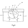
- closures 100 are for locking of the pressure vessel 50 shown in more detail.
- Each shutter 100 faces the diametrically opposite one Connecting sections 64 and 66 of the housing 52 via radial projecting journal 104 rotatably attached to the outside Knobs 102 and 103 on.
- each knob 102 or 103 On the inside of each knob 102 or 103 is a link guide 106 in the form of a groove 108 cut therein spared.
- the groove 108 has a radially opening opening 110, via the one radially from the overlapping section 55 of the cover 54 outwardly projecting link pin 114 can occur.
- the link pin has 114 an end on which a roller 116 or a needle bearing is mounted, a massive one lies inside Shoulder section 118.
- This configuration facilitates handling or the rotary movement of the knob 102 when the shutter is closed 100, which is facilitated by the rolling movement of the roller 116 becomes.
- the shoulder section 118 rests only in the end position form-fitting in the stop 112, through the massive formation of the Shoulder section 118 can be the pressure on the closure 100 forces are well resisted.
- the Knobs 102 are rotated so that openings 110 of groove 108 point upwards, as can be seen from FIG. 3.
- the knobs 102 By turning the knobs 102, the link pin is then 114 brought up to the stop 112.
- FIGS. 9 and 10 It can be seen from FIGS. 9 and 10 that the one on the stand 72 attached lid 54 via a device 120 with the housing 52 is connected.
- the device 120 has a triple telescope 122, in the A relief fader 126 is arranged inside.
- the relief spring 126 is designed so that the weight of the housing 52 is compensated, i.e. on the one hand, it can be very simple and remaining in any height position along the tripod 72 be moved.
- the housing 52 is lowered so far that to the hook 74 at the bottom of the Lid 54 a bag 76 can be attached. Subsequently the housing 52 is raised, as in FIG. 10 by a Arrow 129 is indicated. Now care must be taken that the liquid discharge line 78 into the recess 70 is inserted in the upper edge or in the one recorded therein Form seal 90 is pressed. The case 52 is so far raised until the radially projecting link pins 114 of the Cover 54 in the opening 110 of the groove 108 of the link guide 106 have occurred. Then the rotary buttons 102 twisted, as in Fig. 10 by an arrow 129 in the Knob 102 is indicated. This makes the shutter 100th closed, that is to say the cover 54 is gas-tight with the housing 52 connected, the liquid discharge line 78 protrudes from the pressure vessel 50 before and can then be connected to appropriate equipment be connected.
- the printing medium is then in operation the inner pressure chamber of the pressure vessel 50 inserted and thereby the liquid 80 is pressed out of the bag 76 or derived via the liquid discharge line 78.
- a pressure container 140 has a housing 142 on, similar to that in connection with FIGS. 2 to 10 Described embodiment with two unspecified here Windows is provided.
- a lid 144 is over a telescopically slidable device 155 can be raised or lowered relative to the housing, such as previously in connection with the embodiment of FIGS. 9 and 10 has been described.
- the closures are for the sake of clarity not shown.
- a basket 146 is mounted on the underside of the lid 144, which is provided for receiving one or more bags 160.
- the basket 146 has two side brackets 148, 149, the lower one End region is bent into a U-shape.
- Rod 150, 151 in front which as a spacer or support feet of Basket 146 with respect to the closed bottom of housing 142 serve.
- the two side brackets 148, 149 are over two borders 154, 155 connected.
- the contour of the borders 154, 155 corresponds approximately to that Cross-sectional contour of the housing 142 and these are dimensioned so that they lie at a distance from the inner wall of the housing 142 comes.
- the borders 154, 155 each consist of one to one Oval curved rod.
- the outer ends of the curved rods overlap or laterally overlap each other, so that thereby Hooks 156 and 157 are formed in the side of here
- liquid discharge line not shown, in the form of a hose, as shown in Fig. 1 can be inserted laterally.
- the bottom 152 of the basket 146 is in the form of a serpentine or meandering curved rod is formed, whereby niche-like Areas are formed in which a protruding downward Connection piece of the bag 160 are inserted can, as shown, for example, in the case of the bag 36 in FIG. 1.
- the bag is 160 held by the basket 146 so that no large area Contact with the inner wall of the housing 142 can take place.
- the connecting piece projecting downward from the bottom of the bag 160 can be between the serpentine turns of the ground 152 can be placed. It is sufficient below the floor 152 Space available to the outgoing hose by 180 ° dissipate upwards in the form of a loop. This will then threaded or inserted into the hooks 158, 157, 156 and thus secure and fixed in position to the recess 159 at the upper end of the housing 142, via which the line from the housing is dissipated.
- the bag 160 received in the basket 146 is also in a hook on the underside of the lid 144 hooked.
- a heater can act as a wall of the basket be carried out so that then inserted into the basket Large bag is in contact with the heater.
Landscapes
- Health & Medical Sciences (AREA)
- Animal Behavior & Ethology (AREA)
- Veterinary Medicine (AREA)
- Anesthesiology (AREA)
- Biomedical Technology (AREA)
- Heart & Thoracic Surgery (AREA)
- Hematology (AREA)
- Engineering & Computer Science (AREA)
- General Health & Medical Sciences (AREA)
- Life Sciences & Earth Sciences (AREA)
- Public Health (AREA)
- Vascular Medicine (AREA)
- Physics & Mathematics (AREA)
- Fluid Mechanics (AREA)
- Containers And Packaging Bodies Having A Special Means To Remove Contents (AREA)
- Medical Preparation Storing Or Oral Administration Devices (AREA)
Description
- Fig. 1
- stark schematisiert ein erstes Ausführungsbeispiel eines erfindungsgemäßen Druckbehälters,
- Fig. 2
- eine Seitenansicht eines Gehäuses eines zweiten Ausführungsbeispiels eines erfindungsgemäßen Druckbehälters ohne aufgesetzten Deckel,
- Fig. 3
- einen Querschnitt längs der Linie III-III in Fig. 2,
- Fig. 4
- eine stark vergrößerte ausschnittsweise Darstellung des Behälters von Fig. 2 im Bereich einer Ausnehmung zur Durchführung der Flüssigkeitsabführleitung mit aufgesetztem Deckel,
- Fig. 5
- einen Schnitt längs der Linie V-V in Fig. 4,
- Fig. 6
- eine stark vergrößerte ausschnittsweise um 90° gegenüber der Darstellung von Fig. 2 verdrehte Seitenansicht des Gehäuses mit aufgesetztem Deckel, wobei sich der Drehverschluß in seiner Endstellung befindet,
- Fig. 7
- einen Schnitt längs der Linie VII-VII in Fig. 6,
- Fig. 8
- eine der Darstellung von Fig. 6 vergleichbare Darstellung in einer anderen Betriebsstellung des Verschlusses,
- Fig. 9
- eine Seitenansicht des kompletten Druckbehälters der zweiten Ausführungsform an einem Stativ montiert mit abgesenktem Gehäuse,
- Fig. 10
- eine der Fig. 9 entsprechende Seitenansicht mit geschlossenem Druckbehälter,
- Fig. 11
- eine der Fig. 1 vergleichbare Darstellung eines weiteren Ausführungsbeispiels mit einem am Deckel montierten Korb zur Aufnahme des Beutels, und
- Fig. 12
- eine Seitenansicht der Darstellung von Fig. 11.
Claims (31)
- Druckbehälter zum Beaufschlagen eines in diesem aufgenommenen, mit einer medizinischen Flüssigkeit (80) gefüllten flexiblen Beutels (36, 76, 160) mit Druck, um die Flüssigkeit (80) aus dem flexiblen Beutel (36, 76, 160) abzugeben, mit einem Gehäuse (12, 52, 142), das eine Öffnung (44) zum Einbringen des Beutels (36, 76, 160) aufweist, mit einem Deckel (14, 54, 144) zum Abdecken der Öffnung (44), mit einem Durchbruch zum Abführen einer Flüssigkeitsabführleitung (38, 78) des Beutels (36, 76, 160) aus dem Druckbehälter (10, 50, 140), und mit einem Verschluß (100) zum dichten Verbinden von Deckel (14, 54, 144) und Gehäuse (12, 52, 142), dadurch gekennzeichnet, daß das Gehäuse (12, 52, 142) als stehender, bodenseitig geschlossener, oben offener hohlzylindrischer Körper (16, 56) ausgebildet ist, dessen Querschnitt flachovalförmig ist, und der grob der Querschnittskontur eines Beutels (36, 76, 160) entspricht, und daß die beiden gegenüberliegenden großflächigen stehenden Seitenwände (20, 22, 60, 62), jeweils spiegelbildlich, die Form eines Abschnitts eines Zylindermantels aufweisen, deren seitliche Enden über Verbindungsabschnitte (24, 26; 64, 66) verbunden sind.
- Druckbehälter nach Anspruch 1, dadurch gekennzeichnet, daß der Deckel (14, 54, 144) als die ovale obere Öffnung (44) abdeckender und die Oberkante (28, 68) des Körpers (16, 56) übergreifender Deckel (14, 54, 144) ausgebildet ist.
- Druckbehälter nach Anspruch 1 oder 2, dadurch gekennzeichnet, daß in zumindest einer Seitenwand (20, 60) ein Sichtfenster (48, 82) vorgesehen ist, dessen Scheibe (49, 84) ebenfalls die Form eines Zylindermantelabschnittes aufweist, und daß die Scheibe (49, 84) von der Innenseite (85) des Gehäuses (52) an das Sichtfenster (48, 82) angelegt ist.
- Druckbehälter nach Anspruch 3, dadurch gekennzeichnet, daß im Sichtfenster (82) zumindest ein umfänglich oder axial verlaufender Materialsteg (86) des Materials der Seitenwand (60) stehengeblieben ist.
- Druckbehälter nach einem der Ansprüche 1 bis 4, dadurch gekennzeichnet, daß der Verschluß (100) zumindest einen an der Außenseite des Gehäuses (52) angeordneten Drehknopf (102) aufweist, an dessen Innenseite eine Kulissenführung (106) ausgespart ist, in die ein radial vom Deckel (54) vorstehender Kulissenzapfen (114) einführbar ist, und daß durch Verdrehen des Drehknopfes (102) die Kulisse ein Abnehmen des Deckels (54) vom Gehäuse (52) dichtend sperrt.
- Druckbehälter nach Anspruch 5, dadurch gekennzeichnet, daß der Kulissenzapfen (114) einen von dem Deckel (54) radial vorspringenden zylindrischen Schulterabschnitt (118) aufweist, an den ein mit einer Rolle (116) oder einem Nadellager versehenes Ende folgt, wobei die Kulissenführung (106) derart ausgestaltet ist, daß in einem ersten Drehabschnitt die Rolle (116) oder das Nadellager über eine Rampe (119) läuft, und erst in der Endstellung ein Endabschnitt der Kulissenführung (106) mit Anschlag (112) auf dem Schulterabschnitt (118) des Kulissenzapfens (114) zum Liegen kommt.
- Druckbehälter nach Anspruch 5 oder 6, dadurch gekennzeichnet, daß die Kulissenführung (106) im Bereich des Anschlages (112) hinterschnitten ist.
- Druckbehälter nach einem der Ansprüche 1 bis 7, dadurch gekennzeichnet, daß zwischen Oberkante (68) des Körpers (56) und dem Deckel (14) eine umlaufende V-Dichtung (88) vorgesehen ist.
- Druckbehälter nach einem der Ansprüche 1 bis 8, dadurch gekennzeichnet, daß zwei an den Verbindungsabschnitten (64, 66) der Zylindermantelwände angeordnete, diametral gegenüberliegende Verschlüsse (100) vorgesehen sind.
- Druckbehälter nach einem der Ansprüche 1 bis 9, dadurch gekennzeichnet, daß im Deckel (14, 54) zumindest ein Anschluß (41, 128) für die Zuführung eines Druckmediums in den Druckbehälter (10, 50) vorgesehen ist.
- Druckbehälter nach einem der Ansprüche 1 bis 10, dadurch gekennzeichnet, daß die Innenwand (85) des Gehäuses (12, 52) mit einem Gleitbelag (87) versehen ist.
- Druckbehälter nach einem der Ansprüche 1 bis 11, dadurch gekennzeichnet, daß der Druckbehälter (10, 50) an einem Stativ (32, 72) anbringbar ist.
- Druckbehälter nach Anspruch 12, dadurch gekennzeichnet, daß das Gehäuse (12, 52, 142) über eine längs der Stativachse aus- und einfahrbare Vorrichtung (120, 145) unverlierbar mit dem Deckel (54, 144) verbunden ist.
- Druckbehälter nach Anspruch 13, dadurch gekennzeichnet, daß die Vorrichtung (120, 145) teleskopartig ausgebildet ist.
- Druckbehälter nach einem der Ansprüche 12 bis 14, dadurch gekennzeichnet, daß der Deckel (14, 54) fest mit dem Stativ (32, 72) verbindbar ist, und daß das Gehäuse (12, 52) gegenüber dem Deckel (14, 54) längs der Stativachse verfahrbar ist.
- Druckbehälter nach einem der Ansprüche 13 bis 15, dadurch gekennzeichnet, daß in der Vorrichtung (120) eine Entlastungsfeder (126) vorgesehen ist, die den Verfahrvorgang des Gehäuses (12, 54) erleichtert.
- Druckbehälter nach Anspruch 16, dadurch gekennzeichnet, daß die Entlastungsfeder (126) aus einer Gasfeder, einer Rollfeder oder einer Feder aus einer Gedächtnislegierung besteht.
- Druckbehälter nach einem der Ansprüche 1 bis 17, dadurch gekennzeichnet, daß an der Unterseite des Deckels (14, 54, 144) eine Einhängevorrichtung (34, 74) für einen Beutel (36, 76, 160) vorgesehen ist.
- Druckbehälter nach einem der Ansprüche 1 bis 18, dadurch gekennzeichnet, daß in der Oberkante (28, 68) des Gehäuses (12, 52, 142) zumindest eine Ausnehmung (30, 70, 159) vorgesehen ist, in die von oben die Flüssigkeitsabführleitung (38, 78) des Beutels (36, 76, 160) legbar ist, und dadurch aus dem Gehäuse (12, 52, 142) geführt wird.
- Druckbehälter nach Anspruch 19, dadurch gekennzeichnet, daß in der zumindest einen Ausnehmung (30, 70) eine Formdichtung (90) einsetzbar ist, in die die Flüssigkeitsabführleitung (38, 78) einlegbar ist.
- Druckbehälter nach Anspruch 20, dadurch gekennzeichnet, daß ein die Oberkante (28, 68) des Gehäuse (12, 52) übergreifender Abschnitt (55) des Deckels (52) auch teilweise die Formdichtung (90) überdeckt.
- Druckbehälter nach Anspruch 20 oder 21, dadurch gekennzeichnet, daß die Formdichtung (90) die Gehäusewand (60) im Bereich der Ausnehmung (70) innen und außen übergreift.
- Druckbehälter nach einem der Ansprüche 20 bis 22, dadurch gekennzeichnet, daß die Formdichtung (90) geschlitzt ist, so daß die Flüssigkeitsabführleitung (78) in die Formdichtung (90) eindrückbar ist.
- Druckbehälter nach einem der Ansprüche 1 bis 23, dadurch gekennzeichnet, daß am Gehäuse (12, 52) eine Heizung vorgesehen ist.
- Druckbehälter nach einem der Ansprüche 1 bis 24, dadurch gekennzeichnet, daß am Deckel (144) ein Korb (146) angebracht ist, in den der Beutel (160) einlegbar ist.
- Druckbehälter nach Anspruch 25, dadurch gekennzeichnet, daß der Korb (146) einen Boden (152) aufweist, der im Abstand über dem geschlossenen Boden des Gehäuses (142) zum Liegen kommt.
- Druckbehälter nach Anspruch 25 oder 26, dadurch gekennzeichnet, daß der Korb (146) eine Führung für die Flüssigkeitsabführleitung des Beutels (160) aufweist.
- Druckbehälter nach Anspruch 27, dadurch gekennzeichnet, daß die Führung für die Flüssigkeitsabführleitung Haken (156, 157, 158) aufweist, in die die Flüssigkeitsabführleitung einführbar ist.
- Druckbehälter nach einem der Ansprüche 26 bis 28, dadurch gekennzeichnet, daß der Boden (160) aus einem schlangenlinienförmig gewundenen Stabkörper besteht.
- Druckbehälter nach einem der Ansprüche 25 bis 29, dadurch gekennzeichnet, daß eine Heizung als Wand des Korbes (160) ausgebildet ist.
- Druckbehälter nach Anspruch 30, dadurch gekennzeichnet, daß die der Heizung zugehörigen Steuerelemente auf dem Deckel (144) angebracht sind.
Applications Claiming Priority (3)
| Application Number | Priority Date | Filing Date | Title |
|---|---|---|---|
| DE19733278A DE19733278C2 (de) | 1997-08-01 | 1997-08-01 | Druckbehälter zum Beaufschlagen eines in diesem aufgenommenen, mit einer medizinischen Flüssigkeit gefüllten flexiblen Beutels mit Druck |
| DE19733278 | 1997-08-01 | ||
| PCT/EP1998/004814 WO1999006084A1 (de) | 1997-08-01 | 1998-07-31 | Druckbehälter zum beaufschlagen eines in diesem aufgenommenen, mit einer medizinischen flüssigkeit gefüllten flexiblen beutels mitdruck |
Publications (2)
| Publication Number | Publication Date |
|---|---|
| EP0930902A1 EP0930902A1 (de) | 1999-07-28 |
| EP0930902B1 true EP0930902B1 (de) | 2002-11-20 |
Family
ID=7837676
Family Applications (1)
| Application Number | Title | Priority Date | Filing Date |
|---|---|---|---|
| EP98943819A Expired - Lifetime EP0930902B1 (de) | 1997-08-01 | 1998-07-31 | Druckbehälter zum beaufschlagen eines in diesem aufgenommenen, mit einer medizinischen flüssigkeit gefüllten flexiblen beutels mit druck |
Country Status (4)
| Country | Link |
|---|---|
| US (1) | US6096007A (de) |
| EP (1) | EP0930902B1 (de) |
| DE (2) | DE19733278C2 (de) |
| WO (1) | WO1999006084A1 (de) |
Families Citing this family (40)
| Publication number | Priority date | Publication date | Assignee | Title |
|---|---|---|---|---|
| US7090658B2 (en) | 1997-03-03 | 2006-08-15 | Medical Solutions, Inc. | Temperature sensing device for selectively measuring temperature at desired locations along an intravenous fluid line |
| AU6683498A (en) | 1997-03-03 | 1998-09-22 | Medical Solutions, Inc. | Method and apparatus for pressure infusion and temperature control of infused liquids |
| US7041941B2 (en) | 1997-04-07 | 2006-05-09 | Patented Medical Solutions, Llc | Medical item thermal treatment systems and method of monitoring medical items for compliance with prescribed requirements |
| US6467953B1 (en) | 1999-03-30 | 2002-10-22 | Medical Solutions, Inc. | Method and apparatus for monitoring temperature of intravenously delivered fluids and other medical items |
| US7276675B2 (en) | 1997-04-07 | 2007-10-02 | Patented Medical Solutions, Llc | Medical item thermal treatment systems and method of monitoring medical items for compliance with prescribed requirements |
| US7238171B2 (en) | 2001-03-12 | 2007-07-03 | Medical Solutions, Inc. | Method and apparatus for controlling pressurized infusion and temperature of infused liquids |
| US7031602B2 (en) | 2001-03-12 | 2006-04-18 | Patented Medical Solutions, Llc | Method and apparatus for controlling temperature of infused liquids |
| WO2003030968A1 (en) * | 2001-10-12 | 2003-04-17 | Coloplast A/S | Bowel irrigation system and probe therefore |
| US8226605B2 (en) | 2001-12-17 | 2012-07-24 | Medical Solutions, Inc. | Method and apparatus for heating solutions within intravenous lines to desired temperatures during infusion |
| AU2003283218A1 (en) * | 2002-12-02 | 2004-06-23 | Curatio Aps | Fluid dispenser |
| US7611504B1 (en) | 2004-03-09 | 2009-11-03 | Patented Medical Solutions Llc | Method and apparatus for facilitating injection of medication into an intravenous fluid line while maintaining sterility of infused fluids |
| WO2006102260A2 (en) | 2005-03-21 | 2006-09-28 | Enginivity Llc | Intravenous fluid warming system |
| US7740611B2 (en) | 2005-10-27 | 2010-06-22 | Patented Medical Solutions, Llc | Method and apparatus to indicate prior use of a medical item |
| EP1946786A1 (de) * | 2007-01-19 | 2008-07-23 | Coloplast A/S | Spülsystem mit Pumpe |
| US8226293B2 (en) | 2007-02-22 | 2012-07-24 | Medical Solutions, Inc. | Method and apparatus for measurement and control of temperature for infused liquids |
| US20100204649A1 (en) * | 2007-04-24 | 2010-08-12 | Vidacare Corporation | High Pressure Intraosseous Bag and Method |
| EP2135668B1 (de) * | 2008-06-20 | 2013-08-21 | Fillon Technologies | Vorrichtung zur Lagerung, Auswahl und Dosierung von Grundfarben für das Lackieren, insbesondere das Lackieren von Autos |
| US8092436B2 (en) * | 2008-10-17 | 2012-01-10 | Sterigear LLC | Bodily fluid drainage assembly |
| EP2346546B1 (de) | 2008-10-17 | 2020-08-12 | Sterigear LLC | Drainageanordnung für körperflüssigkeiten |
| US7806865B1 (en) * | 2009-05-20 | 2010-10-05 | Alcon Research, Ltd. | Pressurized irrigation squeeze band |
| USD612937S1 (en) | 2009-06-04 | 2010-03-30 | Sterigear LLC | Bodily fluid drainage bag cover |
| JP5701882B2 (ja) * | 2009-09-10 | 2015-04-15 | サノフィ−アベンティス・ドイチュラント・ゲゼルシャフト・ミット・ベシュレンクテル・ハフツング | 薬剤容器 |
| US8590744B2 (en) * | 2012-01-19 | 2013-11-26 | Timothy E. Orr | Liquid storage dispensing apparatus |
| US9211381B2 (en) | 2012-01-20 | 2015-12-15 | Medical Solutions, Inc. | Method and apparatus for controlling temperature of medical liquids |
| DE102012007697A1 (de) * | 2012-04-19 | 2015-08-13 | Fresenius Medical Care Deutschland Gmbh | Beutel mit Strömungsausgleich |
| US9656029B2 (en) | 2013-02-15 | 2017-05-23 | Medical Solutions, Inc. | Plural medical item warming system and method for warming a plurality of medical items to desired temperatures |
| US20150320929A1 (en) * | 2014-05-09 | 2015-11-12 | Kylie Simonds | Portable intravenous (iv) backpack |
| DE102014017404A1 (de) | 2014-11-25 | 2016-05-25 | Fidica Gmbh & Co. Kg | Überwachung RO-Anlage für Spüllösungen |
| DE102014017399A1 (de) | 2014-11-25 | 2016-05-25 | Fidica Gmbh & Co. Kg | Mischanlage für gebrauchsfertige Spüllösungen |
| DE102014017420A1 (de) | 2014-11-25 | 2016-05-25 | Fidica Gmbh & Co. Kg | Konzentrat für Spüllösungen |
| DE102014017402A1 (de) | 2014-11-25 | 2016-05-25 | Fidica Gmbh & Co. Kg | Anordnung zur Speicherung und Verabreichung von Spüllösungen |
| DE102014017403A1 (de) | 2014-11-25 | 2016-05-25 | Fidica Gmbh & Co. Kg | RO-Anlage für Spüllösungen |
| DE102014017397B4 (de) | 2014-11-25 | 2018-06-21 | Fidica Gmbh & Co. Kg | Fahrbarer Spüllösungsbehälter |
| USD837977S1 (en) | 2016-04-07 | 2019-01-08 | Coloplast A/S | Replacement tubing with connectors adapted for use in anal irrigation system |
| USD828550S1 (en) | 2016-04-07 | 2018-09-11 | Coloplast A/S | Connector of an anal irrigation system |
| USD817483S1 (en) | 2016-04-07 | 2018-05-08 | Coloplast A/S | Anal irrigation catheter adapted for use in an anal irrigation system |
| PL3628356T3 (pl) * | 2018-09-26 | 2022-05-02 | Erbe Elektromedizin Gmbh | Instrument medyczny i urządzenie wytwarzające |
| US20220193331A1 (en) * | 2019-01-30 | 2022-06-23 | Moung Sook LEE | Infusion bag pressing device having pressing bag |
| WO2020205888A1 (en) | 2019-04-01 | 2020-10-08 | Sterigear, Llc | Dual drainage bag, assemblies, and related methods |
| DE102023131505A1 (de) | 2023-11-13 | 2025-05-15 | Marco Systemanalyse Und Entwicklung Gmbh | Medienbehälter |
Family Cites Families (15)
| Publication number | Priority date | Publication date | Assignee | Title |
|---|---|---|---|---|
| CH461034A (fr) * | 1966-06-27 | 1968-08-15 | Werding Wienfried | Appareil de transfusion |
| US3756459A (en) * | 1971-01-12 | 1973-09-04 | Damon Corp | Method and apparatus for metering fluid utilizing pressure differentials |
| ZA726230B (en) * | 1971-09-28 | 1973-05-30 | Bestnu Eng Ltd | Intravenous fluids administration apparatus |
| US3963027A (en) * | 1974-08-16 | 1976-06-15 | Health Technology Labs, Inc. | Medical/surgical suction equipment |
| DE2855270A1 (de) * | 1978-12-21 | 1980-07-03 | Walter Koss | Ernaehrungspumpe |
| DK219881A (da) * | 1980-05-20 | 1981-11-21 | Haemonetics Corp | Apparat til opsugning og samling af en vaeske isaer til brug ved transfusion af eget blod |
| FR2570949A1 (fr) * | 1984-10-02 | 1986-04-04 | Keime Bernard | Injecteur autonome portable pour perfusions notamment dans le cas d'accidentes de la route |
| CA1272918A (en) * | 1986-04-15 | 1990-08-21 | Paul Y. Wang | Compression device enabling flexible solution containers to produce constant delivery rate |
| SE8701305L (sv) * | 1987-03-30 | 1988-10-01 | Kanthal Medical Heating Ab | Blodvaermare |
| US5002534A (en) * | 1988-06-22 | 1991-03-26 | Rosenblatt/Ima Invention Enterprises | Aspirator without partition wall for collection of bodily fluids including improved safety and efficiency elements |
| US5207638A (en) * | 1989-08-24 | 1993-05-04 | Hemotrans, Inc. | Blood transfer apparatus |
| US5053011A (en) * | 1989-09-29 | 1991-10-01 | Harmac Medical Products, Inc. | Disposable pressure infusion system |
| DE4137748A1 (de) | 1991-11-15 | 1993-05-19 | Schiwa Gmbh | Druckbehaelter zum druckbeaufschlagen eines mit einer pharmazeutischen fluessigkeit gefuellten beutels |
| CA2083555A1 (en) * | 1992-11-23 | 1994-05-24 | David H. Laing | Portable infusion device |
| FR2758088B1 (fr) * | 1997-01-06 | 1999-04-16 | Medex Sa | Dispositif d'injection de liquide medical |
-
1997
- 1997-08-01 DE DE19733278A patent/DE19733278C2/de not_active Expired - Fee Related
-
1998
- 1998-07-31 WO PCT/EP1998/004814 patent/WO1999006084A1/de not_active Ceased
- 1998-07-31 DE DE59806350T patent/DE59806350D1/de not_active Expired - Lifetime
- 1998-07-31 EP EP98943819A patent/EP0930902B1/de not_active Expired - Lifetime
-
1999
- 1999-04-01 US US09/283,482 patent/US6096007A/en not_active Expired - Fee Related
Also Published As
| Publication number | Publication date |
|---|---|
| US6096007A (en) | 2000-08-01 |
| EP0930902A1 (de) | 1999-07-28 |
| DE59806350D1 (de) | 2003-01-02 |
| DE19733278C2 (de) | 1999-11-11 |
| DE19733278A1 (de) | 1999-02-11 |
| WO1999006084A1 (de) | 1999-02-11 |
Similar Documents
| Publication | Publication Date | Title |
|---|---|---|
| EP0930902B1 (de) | Druckbehälter zum beaufschlagen eines in diesem aufgenommenen, mit einer medizinischen flüssigkeit gefüllten flexiblen beutels mit druck | |
| DE60007147T2 (de) | Tropffreie lösbare ausgiesstülle | |
| DE102018204532B4 (de) | Servicesystem für eine Fahrzeugklimaanlage und Adaptereinheit für das Servicesystem | |
| DE19723197C2 (de) | Absaugvorrichtung für Körperflüssigkeiten | |
| DE2536746C2 (de) | Vorrichtung zum Absaugen von Flüssigkeit | |
| EP0282956B2 (de) | Fasspumpe | |
| DE3611112A1 (de) | Ernaehrungssystem fuer die enterale ernaehrung | |
| DE3720027C2 (de) | Urinmeßgerät | |
| WO2016192823A1 (de) | Bioreaktorsystem und verfahren | |
| DE69225407T2 (de) | Adapter mit zusatzdichtung für proberöhre | |
| WO1997008068A1 (de) | Einrichtung zur belüftung eines flüssigkeitsbehälters | |
| DE19847031B4 (de) | Entleerungseinrichtung | |
| DE4232318A1 (de) | Gasdichter Silo | |
| DE4202592C2 (de) | Flaschendispenser oder dergleichen mit einem Adapter zur Verbindung mit einer Flasche | |
| EP0175256A2 (de) | Rohrförmiger Zweikammerflüssigkeitsdosierer | |
| DE8806268U1 (de) | Vorrichtung zum selbsttätigen Einziehen von Zapfschläuchen in Zapfsäulen | |
| DE3022644C2 (de) | Prozeßfilter | |
| DE3636887C2 (de) | Transport- und Lagerbehälter mit Schraubverschluß | |
| EP3044304B1 (de) | Behälter mit flexibler wandung | |
| AT500609A4 (de) | Vorrichtung zum entsorgen von flüssigkeiten im medizinischen bereich, insbesondere zum entsorgen von dialysaten | |
| EP0442891A1 (de) | Verfahren und vorrichtung zum einstülpen der membran bei einem auspressfilter für suspensionen. | |
| DE4115580C1 (en) | Irradiation appts. for photochemical reactions - has rotation symmetrical reaction vessel through which flowable medium can pass | |
| DE8631799U1 (de) | Hub- und Verschiebevorrichtung für Container oder Kabinen | |
| DE8628919U1 (de) | Transport- und Lagerbehälter mit Schraubverschluß | |
| DE4426574A1 (de) | Behälter für Flüssigkeiten |
Legal Events
| Date | Code | Title | Description |
|---|---|---|---|
| PUAI | Public reference made under article 153(3) epc to a published international application that has entered the european phase |
Free format text: ORIGINAL CODE: 0009012 |
|
| 17P | Request for examination filed |
Effective date: 19990416 |
|
| AK | Designated contracting states |
Kind code of ref document: A1 Designated state(s): DE FR GB IT |
|
| GRAG | Despatch of communication of intention to grant |
Free format text: ORIGINAL CODE: EPIDOS AGRA |
|
| 17Q | First examination report despatched |
Effective date: 20020301 |
|
| GRAG | Despatch of communication of intention to grant |
Free format text: ORIGINAL CODE: EPIDOS AGRA |
|
| GRAH | Despatch of communication of intention to grant a patent |
Free format text: ORIGINAL CODE: EPIDOS IGRA |
|
| GRAH | Despatch of communication of intention to grant a patent |
Free format text: ORIGINAL CODE: EPIDOS IGRA |
|
| GRAA | (expected) grant |
Free format text: ORIGINAL CODE: 0009210 |
|
| RAP1 | Party data changed (applicant data changed or rights of an application transferred) |
Owner name: STORZ-ENDOSKOP GMBH |
|
| AK | Designated contracting states |
Kind code of ref document: B1 Designated state(s): DE FR GB IT |
|
| REG | Reference to a national code |
Ref country code: GB Ref legal event code: FG4D Free format text: NOT ENGLISH |
|
| REF | Corresponds to: |
Ref document number: 59806350 Country of ref document: DE Date of ref document: 20030102 |
|
| GBT | Gb: translation of ep patent filed (gb section 77(6)(a)/1977) |
Effective date: 20030327 |
|
| ET | Fr: translation filed | ||
| PLBE | No opposition filed within time limit |
Free format text: ORIGINAL CODE: 0009261 |
|
| STAA | Information on the status of an ep patent application or granted ep patent |
Free format text: STATUS: NO OPPOSITION FILED WITHIN TIME LIMIT |
|
| 26N | No opposition filed |
Effective date: 20030821 |
|
| PGFP | Annual fee paid to national office [announced via postgrant information from national office to epo] |
Ref country code: IT Payment date: 20100630 Year of fee payment: 13 Ref country code: GB Payment date: 20100628 Year of fee payment: 13 Ref country code: FR Payment date: 20100824 Year of fee payment: 13 |
|
| PGFP | Annual fee paid to national office [announced via postgrant information from national office to epo] |
Ref country code: DE Payment date: 20110708 Year of fee payment: 14 |
|
| GBPC | Gb: european patent ceased through non-payment of renewal fee |
Effective date: 20110731 |
|
| REG | Reference to a national code |
Ref country code: FR Ref legal event code: ST Effective date: 20120330 |
|
| PG25 | Lapsed in a contracting state [announced via postgrant information from national office to epo] |
Ref country code: FR Free format text: LAPSE BECAUSE OF NON-PAYMENT OF DUE FEES Effective date: 20110801 |
|
| PG25 | Lapsed in a contracting state [announced via postgrant information from national office to epo] |
Ref country code: IT Free format text: LAPSE BECAUSE OF NON-PAYMENT OF DUE FEES Effective date: 20110731 |
|
| PG25 | Lapsed in a contracting state [announced via postgrant information from national office to epo] |
Ref country code: GB Free format text: LAPSE BECAUSE OF NON-PAYMENT OF DUE FEES Effective date: 20110731 |
|
| PG25 | Lapsed in a contracting state [announced via postgrant information from national office to epo] |
Ref country code: DE Free format text: LAPSE BECAUSE OF NON-PAYMENT OF DUE FEES Effective date: 20130201 |
|
| REG | Reference to a national code |
Ref country code: DE Ref legal event code: R119 Ref document number: 59806350 Country of ref document: DE Effective date: 20130201 |