EP0927918A2 - Dispositif pour surveiller une installation se déplaçant le long d'une trajectoire predéterminée, unité de modulation et unité d'exploitation pour ce dispositif - Google Patents
Dispositif pour surveiller une installation se déplaçant le long d'une trajectoire predéterminée, unité de modulation et unité d'exploitation pour ce dispositif Download PDFInfo
- Publication number
- EP0927918A2 EP0927918A2 EP98124873A EP98124873A EP0927918A2 EP 0927918 A2 EP0927918 A2 EP 0927918A2 EP 98124873 A EP98124873 A EP 98124873A EP 98124873 A EP98124873 A EP 98124873A EP 0927918 A2 EP0927918 A2 EP 0927918A2
- Authority
- EP
- European Patent Office
- Prior art keywords
- signal
- unit
- modulator
- modulation
- voltage
- Prior art date
- Legal status (The legal status is an assumption and is not a legal conclusion. Google has not performed a legal analysis and makes no representation as to the accuracy of the status listed.)
- Granted
Links
- 238000011156 evaluation Methods 0.000 title claims description 116
- 230000008878 coupling Effects 0.000 claims abstract description 25
- 238000010168 coupling process Methods 0.000 claims abstract description 25
- 238000005859 coupling reaction Methods 0.000 claims abstract description 25
- 238000012544 monitoring process Methods 0.000 claims abstract description 22
- 238000007493 shaping process Methods 0.000 claims description 7
- 239000004020 conductor Substances 0.000 claims description 6
- 230000004888 barrier function Effects 0.000 claims description 5
- 238000001514 detection method Methods 0.000 abstract description 5
- 238000010586 diagram Methods 0.000 description 19
- 238000011161 development Methods 0.000 description 14
- 230000018109 developmental process Effects 0.000 description 14
- 238000004804 winding Methods 0.000 description 8
- 229910000831 Steel Inorganic materials 0.000 description 7
- 239000010959 steel Substances 0.000 description 7
- 230000033001 locomotion Effects 0.000 description 6
- 230000000694 effects Effects 0.000 description 4
- 230000000903 blocking effect Effects 0.000 description 3
- 230000003287 optical effect Effects 0.000 description 3
- 238000013016 damping Methods 0.000 description 2
- 230000007257 malfunction Effects 0.000 description 2
- 238000005096 rolling process Methods 0.000 description 2
- 230000006641 stabilisation Effects 0.000 description 2
- 238000011105 stabilization Methods 0.000 description 2
- 230000000087 stabilizing effect Effects 0.000 description 2
- 230000006978 adaptation Effects 0.000 description 1
- 230000008901 benefit Effects 0.000 description 1
- 239000003990 capacitor Substances 0.000 description 1
- 230000002950 deficient Effects 0.000 description 1
- 230000002996 emotional effect Effects 0.000 description 1
- 238000005516 engineering process Methods 0.000 description 1
- 239000002184 metal Substances 0.000 description 1
- 238000000034 method Methods 0.000 description 1
- 238000012806 monitoring device Methods 0.000 description 1
- 230000008569 process Effects 0.000 description 1
- 230000009467 reduction Effects 0.000 description 1
- 230000000717 retained effect Effects 0.000 description 1
- 239000000758 substrate Substances 0.000 description 1
- 230000001360 synchronised effect Effects 0.000 description 1
Images


Classifications
-
- H—ELECTRICITY
- H04—ELECTRIC COMMUNICATION TECHNIQUE
- H04B—TRANSMISSION
- H04B5/00—Near-field transmission systems, e.g. inductive or capacitive transmission systems
- H04B5/20—Near-field transmission systems, e.g. inductive or capacitive transmission systems characterised by the transmission technique; characterised by the transmission medium
- H04B5/24—Inductive coupling
-
- E—FIXED CONSTRUCTIONS
- E05—LOCKS; KEYS; WINDOW OR DOOR FITTINGS; SAFES
- E05F—DEVICES FOR MOVING WINGS INTO OPEN OR CLOSED POSITION; CHECKS FOR WINGS; WING FITTINGS NOT OTHERWISE PROVIDED FOR, CONCERNED WITH THE FUNCTIONING OF THE WING
- E05F15/00—Power-operated mechanisms for wings
- E05F15/40—Safety devices, e.g. detection of obstructions or end positions
- E05F15/42—Detection using safety edges
- E05F15/44—Detection using safety edges responsive to changes in electrical conductivity
-
- G—PHYSICS
- G05—CONTROLLING; REGULATING
- G05B—CONTROL OR REGULATING SYSTEMS IN GENERAL; FUNCTIONAL ELEMENTS OF SUCH SYSTEMS; MONITORING OR TESTING ARRANGEMENTS FOR SUCH SYSTEMS OR ELEMENTS
- G05B19/00—Programme-control systems
- G05B19/02—Programme-control systems electric
- G05B19/18—Numerical control [NC], i.e. automatically operating machines, in particular machine tools, e.g. in a manufacturing environment, so as to execute positioning, movement or co-ordinated operations by means of programme data in numerical form
- G05B19/406—Numerical control [NC], i.e. automatically operating machines, in particular machine tools, e.g. in a manufacturing environment, so as to execute positioning, movement or co-ordinated operations by means of programme data in numerical form characterised by monitoring or safety
- G05B19/4061—Avoiding collision or forbidden zones
-
- G—PHYSICS
- G05—CONTROLLING; REGULATING
- G05B—CONTROL OR REGULATING SYSTEMS IN GENERAL; FUNCTIONAL ELEMENTS OF SUCH SYSTEMS; MONITORING OR TESTING ARRANGEMENTS FOR SUCH SYSTEMS OR ELEMENTS
- G05B19/00—Programme-control systems
- G05B19/02—Programme-control systems electric
- G05B19/18—Numerical control [NC], i.e. automatically operating machines, in particular machine tools, e.g. in a manufacturing environment, so as to execute positioning, movement or co-ordinated operations by means of programme data in numerical form
- G05B19/406—Numerical control [NC], i.e. automatically operating machines, in particular machine tools, e.g. in a manufacturing environment, so as to execute positioning, movement or co-ordinated operations by means of programme data in numerical form characterised by monitoring or safety
- G05B19/4062—Monitoring servoloop, e.g. overload of servomotor, loss of feedback or reference
-
- G—PHYSICS
- G05—CONTROLLING; REGULATING
- G05B—CONTROL OR REGULATING SYSTEMS IN GENERAL; FUNCTIONAL ELEMENTS OF SUCH SYSTEMS; MONITORING OR TESTING ARRANGEMENTS FOR SUCH SYSTEMS OR ELEMENTS
- G05B23/00—Testing or monitoring of control systems or parts thereof
- G05B23/02—Electric testing or monitoring
- G05B23/0205—Electric testing or monitoring by means of a monitoring system capable of detecting and responding to faults
- G05B23/0218—Electric testing or monitoring by means of a monitoring system capable of detecting and responding to faults characterised by the fault detection method dealing with either existing or incipient faults
- G05B23/0224—Process history based detection method, e.g. whereby history implies the availability of large amounts of data
- G05B23/0227—Qualitative history assessment, whereby the type of data acted upon, e.g. waveforms, images or patterns, is not relevant, e.g. rule based assessment; if-then decisions
-
- E—FIXED CONSTRUCTIONS
- E05—LOCKS; KEYS; WINDOW OR DOOR FITTINGS; SAFES
- E05Y—INDEXING SCHEME ASSOCIATED WITH SUBCLASSES E05D AND E05F, RELATING TO CONSTRUCTION ELEMENTS, ELECTRIC CONTROL, POWER SUPPLY, POWER SIGNAL OR TRANSMISSION, USER INTERFACES, MOUNTING OR COUPLING, DETAILS, ACCESSORIES, AUXILIARY OPERATIONS NOT OTHERWISE PROVIDED FOR, APPLICATION THEREOF
- E05Y2900/00—Application of doors, windows, wings or fittings thereof
- E05Y2900/10—Application of doors, windows, wings or fittings thereof for buildings or parts thereof
- E05Y2900/104—Application of doors, windows, wings or fittings thereof for buildings or parts thereof for elevators
-
- G—PHYSICS
- G05—CONTROLLING; REGULATING
- G05B—CONTROL OR REGULATING SYSTEMS IN GENERAL; FUNCTIONAL ELEMENTS OF SUCH SYSTEMS; MONITORING OR TESTING ARRANGEMENTS FOR SUCH SYSTEMS OR ELEMENTS
- G05B2219/00—Program-control systems
- G05B2219/30—Nc systems
- G05B2219/37—Measurements
- G05B2219/37633—Output modulated signal on detection of blocking instead of flat signal
Definitions
- the invention relates to a device for monitoring a preferably along a predetermined path movable device, for example one Rolling, sliding gates or an elevator door.
- the device contains a signal generator for generating a fixed frequency carrier signal.
- a modulator unit becomes a modulation signal for modulating the carrier signal, for example depending on the switching state at least one in the specified Path arranged switch generated.
- An electrical coupling device is between the modulator unit and an evaluation device for evaluating the modulated carrier signal arranged.
- the device preferably contains a switching device that a drive device for moving the Movable device effective or ineffective.
- the invention relates also a modulator unit and an evaluation unit for the device to monitor the movable device.
- the pulse width of the modulation signal depending on the state of the two switches changed. If neither switch is closed, the pulse-pause ratio is 1: 1. If one or the other switch is closed, it is the pulse-pause ratio is either 1: 3 or 3: 1.
- An operating state in which Both switches are closed and can be evaluated separately the known device is not provided.
- the known device has one circuit-wise complex modulator unit, because the different Pulse-pause ratios only with a comparatively large amount of circuitry let it be realized.
- the evaluation device is in the known device also expensive, so that to capture the various pulse-pause ratios a computer circuit must be used.
- the modulator unit is constructed so that the carrier signal at a sensor signal deviating from the predetermined sensor signal is not modulated becomes.
- the evaluation unit generates when the unmodulated carrier signal is detected a second monitoring signal deviating from the first monitoring signal.
- the Invention uses the Modulation ON and Modulation OFF states to determine whether there is an obstacle in the path of the movable device. The invention starts from the knowledge that it is easier to determine whether a modulation is present or not to be determined as a pulse-pause ratio. That's why the carrier signal is only modulated in one state of the switch, e.g. in normal condition the switch that indicates that there is no person or object is in the given path.
- the evaluation unit detects the modulation and outputs the first monitoring signal to the control device.
- the control device recognizes from the first monitoring signal that the drive device can continue to be operated. If the switch hits a person or an object, it switches to a stop position, which indicates that the Movement of the gate should be stopped. Switching the switch in the stop position means that the carrier signal is no longer modulated becomes.
- the evaluation device detects the unmodulated carrier signal and generates it the second monitoring signal, whereupon the drive device is stopped becomes.
- the device according to the invention is already used with a single sensor unit used advantageously.
- the circuitry effort for the not mandatory Required modulation is an advantage compared to manual adjustment the operating point of the evaluation unit can be omitted.
- This setting is without Modulation required because, depending on the length of the movable device in the Coupling device damping the signal coming from the sensor unit occurred.
- the evaluation unit can on the other hand, in a very large work area, determine whether the carrier signal is modulated or unmodulated.
- the electrical coupling device on the side the evaluation unit a first inductance and on the side of the modulator unit a second inductor.
- one preferably couples lengthways along the given path, the two inductances.
- two modulator units are used to generate the carrier signal modulate with different frequencies.
- the connections from Safety edges or optical sensors on the modulator units can be used with this Arrangement should be short if the modulator units are close to the sensors to be ordered. With a roller door it is avoided that long connection cables have to be pulled through the gate spar of the roller shutter.
- the modulator units have the same power requirement. Are the modulator units, for example, from the carrier signal fed, it is ensured by the same power requirement that both modulator units have the same supply voltage. At essentially The modulator units then have the same structure in the evaluation circuit demodulated signals have the same amplitude values.
- the signal generator contains a larger output stage Output power, preferably a push-pull output stage.
- the carrier signal can measure the voltage supply to the modulator unit or the modulator units can be used. Also several modulator units can because of the high power their supply voltage from the Obtain carrier signal. Several modulator units can be used without a larger one Connect the effort in series if you use additional coil formers on the steel cable to be ordered.
- the modulator units contain a termination element, that with the modulation switched off with the aid of a switching device is activated on the side of the coupling device.
- a closing element an adjustment resistor is used that is sized is that the modulator unit is independent of the presence of modulation or receives the same supply voltage in the absence of modulation. Located the modulator unit is in the OFF state, it would be without switching on the Closing element the supply power of the other modulator unit lower. If the supply voltage is too low, this modulator unit becomes inoperable. This is prevented by connecting the end element.
- the Modulator unit can be carried out in a small space.
- the signal generator is located on the side of the evaluation unit
- Coupling device operating on the principle of the transmitter also the modulator unit without additional voltage source directly from the via the coupling device transmitted carrier signal are fed.
- a connection of the modulator unit to a mains voltage or the supply via constantly changing Batteries are eliminated.
- the modulator unit contains an overlay device for superimposing several modulation signals.
- the modulation signals preferably have a rectangular waveform.
- the frequency of the Modulation signals are different for each sensor unit.
- the evaluation unit contains a demodulator, which the modulation signal or the superimposed Separates modulation signals from the carrier signal.
- a demodulator which the modulation signal or the superimposed Separates modulation signals from the carrier signal.
- phase locked loops are used as a synchronization circuit.
- the evaluation unit contains a comparison unit for comparing the voltage values on their Entrances. Intermediate switches are located at one input of the comparison unit a clamp circuit that depends on the switching status of the switch modulated or unmodulated carrier signal.
- the comparison unit can also replaced by a transistor: t. At the other input of the comparison unit there is a reference signal.
- the output of the comparison unit is with a Signal shaping unit connected, which is a switching signal for controlling the switching unit generated.
- the signal shaping unit can be essentially with two monostable Build multivibrators. An evaluation circuit is created that only contains few components. There is also alternative development no problems with synchronizing the synchronization circuits.
- the evaluation unit generates the second monitoring signal or a third monitoring signal when the carrier signal is no longer detected becomes.
- the evaluation unit also takes into account that Sensor signal of the sensor unit also the functionality of the coupling device, the modulator unit and the signal generator. If one of these modules falls this is reported by the evaluation unit.
- the second heartbeat e.g. to stop movement of the movable device used.
- the second or third monitoring signal also operates for example an optical or acoustic warning device.
- the invention also relates to an evaluation unit and a modulator unit, which are used in particular in the device according to the invention.
- the technical effects mentioned above therefore also apply to the invention Evaluation unit and the modulator unit according to the invention.
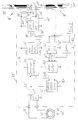
- FIG. 1 shows a block diagram of a device 10 for stopping a schematic illustrated roller doors 12, for example the exit of a property closes.
- the roller shutter 12 shown in plan view is in the two a double arrow 14 indicated directions by means of a not shown Drive device movable.
- On one long side of the roller shutter 12 is one Safety edge 16 arranged in the exit.
- the safety edge 16 contains conductive Buttons 18 and 20 that are compressed by a force F if the roller shutter encounters an obstacle when closing.
- the safety edge 16 is at connections 21a and 21b connected to a modulator 44, which is further below is explained.
- the roller door 12 opens or closes when one is near the gate attached start switch is operated manually. Alternatively or in addition the operation of the gate can also be initiated by means of a remote control. After opening, the roller door 12 remains for a predetermined time, for example opened so that a vehicle can pass. After the given The roller shutter 12 closes automatically. Is still a at this time Vehicle or a person in the exit, the force F is generated as soon as the gate hits the person or object. With the one shown in Figure 1 Circuit becomes automatic when buttons 18 and 20 are closed Closing the roller door 12 interrupted until the buttons 18 and 20 again come to their rest position and a new starting process is carried out.
- a steel cable 24 is on the gate body 22, to which the safety edge 16 is also attached excited that together with the conductive gate body 22 a conductor loop 26 forms.
- the steel cable 24 runs through the ring centers of two ring coils 28 and 30.
- the toroidal coil 28 is arranged stationary, so that the steel cable 24 at one Movement of the roller door 12 through the ring coil 28 without contact emotional.
- the ring coil 30 moves like the switching strip 16 with the Roller door 12.
- the ring coil 28 has a core 32 around which the turns of a winding 34 run. One end of the winding 34 is connected to a ground line M. The other end of the winding 34 is connected to one terminal of a matching resistor 36 connected. The other connection of the matching resistor 36 is connected to the output of a signal generator 38. In the signal generator 38 becomes a sinusoidal primary signal PS with a carrier frequency generated by 10 kHz, for example. also Figure 4.
- the ring coil 30 has 40 turns of a winding 42 on a core as well.
- the two ends of the winding 42 are in the modulator 44 in time with a modulation frequency f1 of e.g. 1 kHz short-circuited if the safety edge 16 is in its normal state in which the buttons 18 and 20 are not touch and in which the circuit through the safety edge 16 and with a Load resistor 50 is closed.
- a modulation frequency f1 e.g. 1 kHz
- the ring coils 28 and 30 and the conductor loop 26 form a transformer U, Via which the modulator 44 acts on the primary signal PS and an evaluation signal AS generated on the ring coil 28.
- a secondary signal SS is present on the ring coil 30 on.
- the modulator 44 modulates the primary signal in the normal state of the safety edge 16 PS, so that a modulated secondary signal SS is generated, cf. also Figure 4.
- An evaluation circuit 46 detects whether that is present at its input Evaluation signal is modulated by the modulator 44. If this is the case, then A voltage is output at an output A1, which is a voltage shown in FIG Relay 108 holds in its working state.
- the drive device is in the working state of the roller shutter 12 effective.
- the primary signal PS is no longer modulated.
- the unmodulated primary signal PS is present as an evaluation signal AS.
- the evaluation circuit 46 detects the absence of the modulation and outputs at the output A1 a voltage of plus 12 volts.
- the relay 108 at the output of the evaluation circuit 46 drops and interrupts, for example, the energy supply to the drive device of the roller shutter 12, so that the roller shutter 12 stops.
- a high-resistance load resistor 50 connects the buttons 18 and 20 of the Safety edge 16. Is the load resistor 50 due to an interruption in the Buttons 18 or 20 themselves or in the feed lines to the modulator 44 are not more effective, the modulation is set in the modulator 44. Through this Measure prevents malfunction of the device 10.
- FIG. 2 shows a block diagram of the modulator 44.
- the secondary signal SS rectified by means of a bridge rectifier 51.
- modulator element 52 can the rectified secondary signal DC shorted to ground. This short circuit affects the Rectifier 51 directly out onto the ring coil 30.
- the modulator element 52 short-circuits the connections of the winding 42.
- the rectified secondary signal GS is in the modulator 44 of a stabilizing circuit 54 fed regardless of whether the rectified secondary signal GS is modulated or unmodulated, a sufficiently stable supply voltage Uc generated. An additional power supply for the modulator 44 by a battery or a power supply is therefore not necessary.
- the modulator 44 contains a multivibrator 56 which has a sawtooth voltage US generated with a frequency of 2 kHz.
- Sawtooth tension US is at the negative input of an operational amplifier operating as a comparator 58 at.
- At the positive input of the operational amplifier 58 is by means of a Voltage divider consisting of a resistor R1 and the load resistor 50 a generates positive reference voltage Vref, which is approximately the mean value of the sawtooth voltage US has.
- the voltage at the positive input of the operational amplifier 58 deviates from the reference voltage Vref when the safety edge 16 is actuated is, or if an interruption of the by the switching bar 16 and the Load resistance 50 formed circuit occurs. That is why the actual Voltage at the positive input of operational amplifier 58 as voltage U1 referred to, cf. also Figure 5.
- the output of the operational amplifier 58 is connected to a via a line 60 Flip flop 62 connected.
- the voltage at the output of operational amplifier 58 is referred to as U2, cf. also FIG. 5.
- the voltage U3 has at effective modulation only a frequency of 1 kHz, because the flip-flop 62 as Divider works.
- the output of flip-flop 62 is at the input of a flip-flop 64 connected so that the two flip-flops 62 and 64 are connected in series.
- a voltage U4 arises at the output of the flip-flop 64, cf. also Figure 5.
- the output of the flip-flop 64 is connected directly to the modulator element 52.
- the flip-flops 62 and 64 are connected so that the voltage U4 is only rectangular is when the safety edge 16 is in its normal state. Is the safety edge 16 pressed or the circuit is interrupted by the safety edge 16, the voltage U4 has the value 0 volts, and the modulator element 52 switches Not. This means that in these cases there is no modulation of the secondary signal SS occurs. Due to the coupling by means of transformer Ü, cf. Figure 1 also occurs the evaluation circuit 46 does not modulate the evaluation signal AS, cf. Figure 1.
- FIG. 3 shows a block diagram of the evaluation circuit 46.
- the evaluation signal AS is connected to the positive input of a comparator 100 a clamp circuit, not shown. Such clamp circuits are known from television technology. You have the task of a voltage swing to create.
- the evaluation signal AS thus raised has a voltage profile U5, cf. also Figure 6.
- the negative input of comparator 100 is connected to the ground line M. There is one at the output of the comparator 100 Voltage U6 on, cf. also FIG. 6. The mode of operation of the comparator 100 is also explained below with reference to FIG. 6.
- the output of the comparator 100 is with the input of a first monoflop 102 connected, which has a falling clock edge its output at H level switches until a specified switching time has expired, which is approximately the period of the primary signal PS with the frequency of 10 kHz, i.e. about 100 ⁇ s.
- a voltage curve U7 is present at the output of the monoflop 102, cf. Figure 6.
- the output of the monoflop 102 is connected to the input of a monoflop 104, which also with a falling clock edge at its input Output switches to H level.
- the switching time of the monoflop 104 corresponds approximately the period of the modulation signal of 1 kHz, i.e. a time of about 1 ms.
- a voltage curve arises, which is shown below Hand of Figure 6 is explained in more detail.
- the inverting output A1 of the monoflop 104 with a voltage profile U8, cf. FIG. 6 is with the one connection of an armature coil 106 of the relay 108 connected.
- the other connection of the armature coil 106 is at the positive operating voltage connected to the evaluation circuit 46.
- has the inverting output A1 of the monoflop 104 H level the normally open contact 110 is open. The drive device of the roller shutter 12 and thus also the movement of the roller shutter 12 itself stopped.
- evaluation signal AS is not is more modulated. This is the case when the safety edge 16, cf. Figure 1, pressed is, the circuit is interrupted by the safety edge 16 or if the transmitter U or the modulator 44 is working incorrectly.
- the evaluation signal AS is also not modulated if 38 due to a defective signal generator the primary signal PS is not generated.
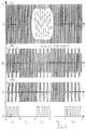
- Figure 4 shows waveforms in the circuit of Figure 1, so that when explaining FIG. 4 also refers to FIG. 1.
- Figure 4 shows in the Sequence from top to bottom the voltage profiles of the primary signal PS, the evaluation signal AS, the secondary signal SS and the voltage U4, cf.
- the voltage values U of the voltage profiles are in each case on a common one Ordinate axis 113 removed. Is on the abscissa axes the time t removed.
- the course of the primary signal PS is in the upper coordinate system of FIG shown.
- the primary signal PS is a sine signal with a frequency of 10 kHz, cf. the enlargement PS *.
- the primary signal PS is modulated generates the evaluation signal AS.
- the evaluation signal AS is in the second coordinate system from above in FIG. 4 shown.
- the evaluation signal AS has a carrier frequency of 10 kHz with the modulation frequency is modulated by 1 kHz.
- the degree of modulation is about 40%, due to the damping effect in the transformer Ü, cf. Figure 1.
- By the modulation leads to a temporary reduction in the amplitude of the Carrier signal, cf. Modulation gaps 114.
- the secondary signal SS is in a coordinate system below the coordinate system shown for the evaluation signal AS. At the modulator 44 is the Degree of modulation about 100%.
- the carrier signal of the secondary signal SS with a Frequency of 10 kHz is therefore synchronized with the modulation frequency of 1 kHz trimmed to about 0 volts in amplitude. This creates gaps in modulation 116.
- the time period T1 begins at a time t0 and ends a time t1.
- the time periods T2 are connected to the time period T1 to T5 in this order.
- the time period T2 thus begins at the time t1.
- the periods T3, T4 and T5 begin at times t2, t3 and t4.
- the stopping device 10 operates of the roller shutter 12 in its normal operating mode, in which no force F is applied to the safety edge 16 acts and in which also the circuit formed by the switching strip 16 closed is.
- the modulator 44 modulates the evaluation signal AS.
- the circuit is interrupted by the safety edge 16 because for example, a connecting line of the switching strip 16 due to weather conditions has been interrupted.
- the break leads as shown below with the figure 5 explains the absence of modulation.
- the absence of modulation of the evaluation signal AS is recognized in the evaluation circuit 46.
- the roller shutter 12 is stopped if it is in motion.
- One press of the roller door 12 is not possible if the modulation of the evaluation signal AS is missing.
- FIG. 5 shows signal profiles in the modulator 44, so that when FIG. 5 is explained reference is also made to FIG.
- Figure 5 there are five coordinate systems shown with a common ordinate axis 120, on each Voltage values U are removed. On the abscissa axes of the coordinate systems the time t is removed. The times t0 to t4 again denote the Limits between the time periods T1 to T5. Lines 122 illustrate this Limits between the time periods T1 to T5.
- the sawtooth tension US is shown in the uppermost coordinate system in FIG.
- the average value of the sawtooth voltage US is half the supply voltage Uc.
- the sawtooth voltage US fluctuates between a lower one Voltage value at about a third of the supply voltage Uc and one upper voltage value at about two thirds of the supply voltage Uc.
- the sawtooth voltage US has the same in all time periods T1 to T5 Waveform.
- the second coordinate system shows the voltage U1 on the switching strip 16.
- a horizontal line 124 shows the value of the reference voltage Vref, which is half the supply voltage Uc in the exemplary embodiment.
- a horizontal line 126 illustrates a voltage value that is one third of the Supply voltage Uc corresponds.
- a horizontal line 128 shows finally a voltage value that is two thirds of the supply voltage Uc corresponds.
- the voltage U1 matches the reference voltage Vref, which is the setpoint for voltage U1 in normal mode pretends.
- the operational amplifier 58 compares the Voltage value U1 with the constantly changing voltage values of the sawtooth voltage US. As long as the voltage value U1 in the time periods T1, T3 and T5 lies within the voltage range in which the voltage values are the sawtooth voltage US will move at the output of the operational amplifier 58 generates a rectangular signal in the central coordinate system 5 is shown as voltage curve U2.
- the voltage U1 is equal to 1/2 Uc, so that the pulse duration of the rectangular signal of the voltage U2 equal to the time for the Pulse pause is.
- the voltage U1 has a value which is above the Voltage is two thirds of the supply voltage Uc.
- the voltage at the positive input of operational amplifier 58 is permanent greater than the voltage values of the sawtooth voltage US on the negative Input of operational amplifier 58.
- the result is that the output of the operational amplifier 58 and thus the voltage U2 permanently at a high Voltage value, for example plus twelve volts.
- the voltage value U1 is reached by pressing the safety edge 16 pulled below a voltage value that is one third of the supply voltage Uc corresponds.
- the voltage value at the positive input of the operational amplifier 58 is permanently smaller than the voltage values of the saw tooth voltage at the negative input of operational amplifier 58. Therefore, on Output of operational amplifier 58 the voltage value 0 volts is output, until the time t4 the switching bar 16 is released again.
- the effect of the flip-flop 62 on the voltage curve U2 is in a coordinate system shown for the voltage U3.
- the flip-flop 62 divides the clock frequency the rectangular voltage U2 in the case of modulation, i.e. in the periods T1, T3 and T5. In the periods T2 and T4, the by Maintain voltage U2 predetermined signal curve.
- the voltage U4 is at the output of the flip-flop 64.
- the flip-flop 64 is connected so that the switching frequency is retained at its entrance also at the exit. Through the outside Wiring of the flip-flop 64 is achieved, however, that a permanent positive Voltage value of voltage U4 is suppressed.
- the tension U4 in the time segments T1, T3 and T5 a rectangular waveform.
- the voltage U4 has the voltage value 0 volts. Therefore, the modulator element 52 in the time periods T2 and T4 are not controlled, so that the modulation of the secondary signal SS, the rectified secondary signal GS and the evaluation signal AS is omitted.
- Figure 6 shows waveforms in the evaluation circuit 46, so that when explaining 6 also refers to FIG. 3.
- Figure 6 there are six coordinate systems shown with a common ordinate axis 140 on which Voltage values U are removed.
- the coordinate systems each have one Axis of abscissa on which time t is plotted.
- Lines 142 illustrate the Limits between the time periods T1 to T5.
- the voltage U5 is shown in the coordinate system below With the help of the clamping circuit on the positive pole of the comparator 100 is generated.
- the Clamping circuit causes a leakage resistance by means of a coupling capacitor and a diode, which can also be the substrate diode of the comparator can that the voltage U5 compared to the voltage values of the evaluation signal AS is raised.
- the voltage U5 is raised so far that even with a low degree of modulation, the lower envelope of the voltage U5 contains negative voltage peaks 144, between which areas with positive lower amplitude values.
- the middle coordinate system in FIG. 6 shows the voltage U6 at the output of comparator 100.
- the voltage U8 is at the inverting one Output of the monoflop 104 downstream of the monoflop 102 is shown.
- the monoflop 104 also switches with falling signal edges.
- the Switching time of the monoflop 104 is approximately the same as the period of 1 ms Modulation signal, i.e. a signal with a frequency of 1 kHz, match.
- the gaps between the Rectangular pulses 146 due to immediately successive switching operations of the monoflop 104 closed. This is due to the non-inverting output a high positive voltage value appears in time periods T1, T3 and T5, for example plus 12 volts.
- the inverting output is due to the inversion in the periods T1, T3 and T5 the voltage value 0 volts.
- This Voltage value causes due to the wiring of the relay shown in Figure 3 108 that the relay 108 is switched on and the normally open contact 110 is closed becomes.
- the roller door 12 can thus be operated.
- FIG. 7 shows a block diagram of a device 10 'for actuating a Roller doors 12 'shown in plan view.
- Figure 7 is essentially the same as Figure 1 match, so that modules with the same function are not explained again become. However, these modules are given a distinction superscript dash.
- the switching strips 16 'and 16' ' are essentially built like the safety edge 16.
- the safety edge 16 '' is like that Safety edge 16 'connected to the modulator 44', cf. Connections 21a ', 21b' and 21a '' and 21b ''.
- roller door 12 ' moves to the right, an obstacle standing in the exit exercises a force F ', which presses the safety edge 16'. If the roller door 12 ' on the other hand, it opens to the right through an obstacle in the way exerts a force F '' which actuates the safety edge 16 ''.
- the signal generator 38 ' is constructed like the signal generator 38, cf. Figure 1
- the structure of the modulator 44 ' is explained in more detail below with reference to FIG. 8.
- the evaluation circuit 46 has another in addition to the output A1' Exit A2.
- the output A1 ' serves to actuate the drive device, not shown of the roller shutter 12 'depending on the switching status of the safety edge 16 '.
- the output A2 serves to actuate the drive device of the Roller doors 12 'depending on the switching status of the safety edge 16' '.
- the evaluation circuit 46 detects the respective modulation state of the evaluation signal AS 'and actuates the drive device of the roller door 12' so that a safe Operation of the roller door 12 'is guaranteed.
- the structure of the evaluation circuit 46 ' is explained in more detail below with reference to FIG. 9.
- FIG. 8 shows a block diagram of modulator 44 '.
- Modules in the modulator 44 ' with the same function as in the modulator 44 according to FIG. 3 have in FIG. 2 the same reference number, but with a prime and in the case of double version with two superscript lines.
- the modulator 44 ' contains for both switching strips 16 ', 16' 'together a rectifier 51', a modulator element 52 'and a stabilizing circuit 54'.
- a multivibrator 56 'belonging to the switching strip 16' generates a sawtooth voltage US 'with a frequency of 2 kHz.
- an operational amplifier 58 'and a flip-flop 62' are used for the switching strip 16 ' used as above with the operational amplifier 58 and the flip-flop 62 explains work.
- Another multivibrator 56 ′′ generates a sawtooth voltage US '' with a frequency of 1.6 kHz, which in an operational amplifier 58 '' is compared with a voltage U1 '' at the connection 21a '' of the switching strip 16 ''.
- the output of operational amplifier 58 ′′ is at the input of a flip-flop 62 '' connected.
- a first modulation voltage U3 'for arises at the output of the flip-flop 62' a first channel belonging to the switching strip 16 '.
- At the output of the flip-flop 62 '' creates a further modulation voltage U3 'for one to the switching strip 16' ' belonging second channel.
- the modulator 44 ' is therefore in contrast to the single-channel modulator 44 by a modulator with two modulation channels.
- the two voltages U3 'and U3' ' are applied to the inputs of a NOR gate 160 performed, which the voltage values at its inputs according to a NOR function linked.
- Has a voltage at the output of gate 160 V10 only a positive value if at both inputs of the gate 160 there is a voltage of 0 volts.
- the voltage U10 acts directly on the modulator element 52 '. With a high positive voltage value, the modulator element switches 52 'retrospectively via the rectifier 51', the winding 42 'briefly so that To modulate secondary signal SS 'and thus also the evaluation signal AS', cf. also Figure 7.
- the voltages U2 'and U2' ' are still at the inputs of a blocking circuit 162, which causes the modulator element 52 'to be no longer than one predetermined time is controlled, for example the time for half a clock period of the 800 kHz modulation clock.
- Another blocking circuit 164 ensures that the modulator element 52 'also works correctly when it is switched on.
- FIG. 9 shows a block diagram of the evaluation circuit 46 '.
- the evaluation signal AS ' is in the evaluation circuit 46' at the input of a demodulator circuit 170 created.
- a voltage is present at the output of demodulator circuit 170 U11, the course of which is explained in more detail below with reference to FIG. 11 becomes.
- Demodulator circuit 170 includes a rectifier.
- a filter circuit 172 is connected downstream of demodulator circuit 170. At the The output of the filter circuit 172 is at a voltage U12, the voltage profile of which essentially follows the modulation curve in the evaluation signal AS '.
- a tone with a frequency of 1 kHz is in the voltage curve U12 recorded. If a tone with a frequency of 1 kHz is used by the Tone decoder 174 detected, the voltage value 0 volts is generated at the output A1 '. The relay 108 'picks up and closes the normally open contact 110'. This becomes the normal operating mode the switching bar 16 'is detected and the roller shutter 12' can be operated. If the tone with a frequency of 1 kHz is not included in the evaluation signal AS ' detected by the sound decoder 174, there is a voltage of plus at the output A1 ' 12 volts. The relay 108 'drops out and opens the normally open contact 110'. The roller shutter 12 'cannot be operated if either the safety edge 16' is pressed or if the circuit is interrupted by the safety edge 16 '.
- the voltage U12 is also present at the input of a sound decoder 176, the one 800 Hz tone detected. Is such a tone in the evaluation signal AS 'and thus also in the voltage curve before the voltage U12, so the output of the sound decoder 176 a voltage value of 0 volts.
- the relay 108 '' thus picks up and closes the working contact 110 ''.
- Relay 108 '' opens the make contact 110 ''.
- the roller door 12 ' cannot be operated if either an obstacle presses on the safety edge 16 '', or the circuit through this safety edge 16 '' is interrupted.
- the evaluation circuit 46 ' also contains an error detection 180.
- An on the error detection connected LED 182 only does not light up, when the evaluation circuit 46 'detects a modulated evaluation signal AS'.
- the Error detection 180 is similar to the evaluation circuit explained with reference to FIG. 3 46 built.
- Figure 10 shows waveforms in the modulator 44 ', so that when explaining the figure 10 with reference to FIG. 8.
- time t is ablated in each case.
- T10, T12 and T14 are both switching strips 16 'and 16' 'in their normal operating mode.
- T11 the safety edge 16 'is pressed and the safety edge 16' 'is in their Normal operating mode.
- T13 only the safety edge is switched on 16 '' pressed and the safety edge 16 'is in its normal operating mode.
- the uppermost coordinate system in FIG. 10 shows the voltage curve of the Voltage U3 'at the output of flip-flop 62'.
- Switch bar 16 'in the time period T10 rectangular pulses 190 are generated. Becomes the safety edge 16 'pressed in the time period T11 or the circuit is through the switching strip 16 'interrupted, the voltage U3' remains permanently on the Voltage value 0 volts, cf. Pulse gap 192. If the safety edge 16 'is released again, voltage U3 'again has a rectangular waveform, see. Rectangular pulses 194.
- the rectangular pulses 190 and 194 have a pulse frequency of 1 kHz.
- the voltage U3 '' is a coordinate system shown for the voltage U3 ''. Is the safety edge 16 '' in the time periods T10, T11 and T12 of their normal operating mode, the voltage U3 '' has one rectangular course with rectangular pulses 200, the pulse frequency of 800 Hz. If the safety edge 16 '' is pressed, the voltage remains U3 '' at the voltage value 0 volts until the safety edge 16 '' in the period T14 is released. A pulse gap arises in the time period T13 202 until the voltage U3 ′′ in the time period T14 is again rectangular Has waveform, cf. Rectangular pulses 204.
- the signal curve of a NOR link the waveforms for the voltages U3 'and U3' '.
- the voltage U10 has a high positive value only if both voltages U3 'and U3 '' have the voltage value 0 volts.
- the course of the voltage shown in FIG. 10 U10 represents a possible course, but is not one of the voltage courses of voltages U3 'and U3' '.
- the voltage U10 has one rectangular waveform with rectangular pulses 210 that are different Have pulse widths. In this context it is also of a rectangular shape Course spoken with random pulse width. The pulse width however not larger than the pulse width of the rectangular pulses 200 or 204.
- the course of the evaluation signal is in the lowest coordinate system of FIG AS 'shown.
- the evaluation signal AS ' was shown in Figure 10 for completeness. It does not occur in the modulator 44 'but on the evaluation unit 46'.
- the evaluation signal AS ' is only modulated with the frequency 800 Hz.
- the evaluation signal AS ' is only with the frequency of 1 kHz modulated.
- Figure 11 shows waveforms in the evaluation unit 46 ', so that when explaining FIG. 11 also refers to FIG. 9.
- FIG. 11 there are three Coordinate systems are shown that have a common ordinate axis 220. Voltage values U are plotted on the ordinate axis 220.
- the coordinate systems in FIG. 11 each have their own abscissa axis on which the time t has been removed.
- the signal curve of the voltage is in the central coordinate system of FIG U11 shown at the output of demodulator circuit 170. Only positive voltage values of the evaluation signal AS 'can pass through the demodulator 170 and appear as output voltage U11.
- the course of the voltage U12 is in the lower coordinate system of FIG shown.
- the high-frequency component of 10 kHz was eliminated by the filter 172 filtered out the voltage curve U11.
- the course of the voltage U12 follows essentially the envelope of the voltage curve U11.
- both capture sound decoders 174 and 176 respectively Calibration frequency of 1 kHz or 800 Hz.
- Ton decoder 176 In period T11 only the Ton decoder 176 its calibration frequency of 800 Hz.
- the tone decoder 174 has its calibration frequency of 1 kHz.
- Tone decoders 174 and 176 are synchronizing circuits that relate to their Want to synchronize calibration frequencies. As soon as a sufficiently stable synchronization is present, the output signal of the tone decoders 174 and 176 switched. So-called phase-locked loops are in the tone decoders 174 and 176 included, called "phase locked loop".
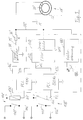
- FIG. 12 shows a block diagram of a device 10a for stopping a Roller doors 12a.
- the device 10a differs from that above with reference to FIG Figure 7 explained device 10 'in that not a modulator 44' but two modulators 44a and 44b can be used.
- On the long sides of the A switching strip 16a or 16b is fastened to roller doors 12a.
- the safety edge 16a or 16b is constructed like the safety edge 16 'or 16' '.
- the safety edge 16a is connected to the modulator 44a which transmits the primary signal PS at a frequency modulated by 1 kHz.
- the modulator 44a is by means of a ring coil 30a coupled to a signal generator 38a, which generates the primary signal PS.
- the signal generator 38a generates a primary signal in comparison to the signal generator 38 ' PSa higher performance because it contains a push-pull amplifier.
- the Outputs of the signal generator 38a are interposed by matching resistors 36a and 36b connected to a ring coil 28a.
- the ring coils 28a, 30a and a further ring coil 30b comprise a steel cable 24a, which is stretched in the longitudinal direction of the metal roller shutter 12a, so that a transformer Üa is formed, the function of which was explained with reference to FIG. 7 Transmitter Ü 'corresponds.
- an evaluation circuit 46a corresponds to that of the evaluation circuit 46 ', cf. Figure 7. However, the evaluation circuit 46a has two inputs, each with the end of the matching resistor leading to the ring coil 28a 36a and 36b are connected. The structure and function of the evaluation circuit 46a is explained in more detail below with reference to FIG. 14.
- the switching bar 16b is connected to the modulator 44b.
- the modulator 44b modulates the primary signal PSa with a frequency of 800 Hz.
- the modulator 44b is connected to the ring coil 30b for this purpose.
- FIG. 12 enables short connecting lines 250, 252 to connect the switching strip 16a to the modulator 44a.
- short connecting lines 254 and 256 are used to connect the safety edge 16b to the modulator 44b.
- the connecting lines at least one Safety edge 16 'or 16' 'laboriously through the gate spar of the roller door 12, 12' must be laid, the connecting lines 252 to 254 in the embodiment 12 in a simple manner with the modulator 44a or 44b get connected.
- FIG. 13 shows a block diagram of the modulator unit 44a. Shown in Figure 13 Functional elements, which essentially as already explained with reference to FIG. 2 Functional elements are constructed, have the same reference numerals in Figure 13, however with the lower case letter a. Signals SSa, GSa, U1a, USa, U2a, U3a and U4a have the same course as the corresponding ones Signals SS, GS, U1, US, U2, U3 and U4. Therefore, on the basis of the Figures 4, 5 and 6 explained courses of these signals referenced.
- the modulator 44a also includes a monostable multivibrator 300, the Input is connected to the output of flip-flop 64a, so that at the input the voltage U4a is present.
- the output of the multivibrator 300 is via one Load resistor RL connected to the output of rectifier 51a.
- the load resistance RL is missing Voltage pulses of voltage U4a activated against ground, i.e. for example in the time periods T2 and T4 according to FIG. 5.
- the modulator 44b is constructed essentially like the modulator 44a however with a modulation frequency of 800 Hz. Both modulators 44a and 44b have the same power consumption. As a result, their supply voltages Uc and thus the modulated signals are the same Have amplitudes. When demodulating in the evaluation circuit 46a then the demodulated signals have the same amplitudes. This simplifies the evaluation of these signals significantly.
- FIG. 14 shows a block diagram of the evaluation circuit 46a. Shown in Figure 14 Functional elements, which essentially as already explained with reference to FIG. 9 Functional elements are constructed have the same reference numerals in FIG. 14, however without a prime and with a lower case letter a.
- the signal generator 38a has a push-pull output stage, so that, in contrast to the signal generator 38 ', two output lines are used, each with the matching resistor 36a and 36b are connected.
- An evaluation signal ASa essentially corresponds to that on hand the evaluation signal AS 'explained in FIG. 9. However, the evaluation signal ASa a slightly different course because two individual modulators 44a and 44b instead of the modulator 44 'can be used. While in the modulator 44 'the modulation signals different modulation frequency with the help of the NOR gate 160 were superimposed in the exemplary embodiment according to FIGS to 14 superimposed the modulation signals in the transformer Üa.
- the evaluation circuit 46a contains one downstream of the demodulator 170a Filter circuit 172a, which also contains a control amplifier. At the exit The filter circuit 172a generates a voltage U12a, which is approximately the course which has voltage U12, cf. Figure 11.
- a digital filter 310 is on the input side connected to the output of the filter circuit 172a. The digital filter 310 generates a predetermined output signal when the voltage curve U12a is a modulation frequency of 1 kHz contains.
- a comparator is at the output of the digital filter 310 312 connected, the relay 108a depending on the output signal of the digital filter 310 is actuated. Ultimately, relay 108a is switched as the relay 108 'explained with reference to FIG. 9.
- the input of a digital filter 320 is also connected to the output of the filter circuit 172a connected.
- the digital filter 320 generates a predetermined one at its output Output signal if at its input a frequency or a Frequency component of 800 Hz is present.
- a Comparator 322 connected, which depends on the output signal of the digital filter 320 the relay 108b switches.
- relay 108b is switched so as has been explained above with reference to FIG. 9 for the relay 108 ′′.
- the Frequencies of the modulators 44a and 44b are chosen so that the digital filters Filter 310, 320 safely. Thus, frequencies other than 1 kHz and 800 Hz used.
- FIG. 15 shows a modulator 44c, which instead of the modulator 44, 44a or 44b is used.
- Functional elements shown in Figure 15 which are essentially like Functional elements already explained with reference to FIG. 2 are constructed in FIG. 15 the same reference number, but with the lower case letter added c.
- a light barrier 330 is used in FIG. 15, which have a light transmitter 332, e.g. a light emitting diode, and a light receiver 334 contains, e.g. a photodiode.
- An opto-transmitter 336 is connected to the stabilization circuit 54c is connected and is supplied with the supply voltage Uc.
- the opto-transmitter 336 switches the light transmitter 332 at a frequency of 1 kHz on and off, the pulse-pause ratio being either 1: 1 or e.g. 1:10 is. As a result, the light transmitter 332 emits a light beam LS at this frequency down to the light receiver 334.
- the light receiver 334 is on one Opto-Receiver 338 connected, also by the supply voltage Uc is supplied.
- the opto-receiver 338 amplifies that of the light receiver 334 generates signals and controls the modulator element 52c with the voltage U4c on.
- the voltage U4c essentially has the course of the voltage U4, cf. Figure 5.
- the Light receiver 334 no longer receive a modulated light signal.
- the modulation stops on the side of the opto-receiver 338, so that the modulator element 52c is in the OFF state. So that the primary signal PS is no longer modulated. Only when the obstacle no longer interrupts the light beam LS resumes the modulation.
- a light emitting diode is used as the light transmitter 332, which is in the infrared range is working.
- the light barrier 330 is a non-contact Switching possible.
- the modulator 44c is simply constructed, since the operational amplifier 58 and the flip-flops 62 and 64 are omitted, cf. Figure 2nd
- a monostable multivibrator 300 ' and a load resistor RL ' is used, which explained the above with reference to FIG. 13 Functional elements 300 and RL correspond.
Landscapes
- Engineering & Computer Science (AREA)
- Physics & Mathematics (AREA)
- General Physics & Mathematics (AREA)
- Automation & Control Theory (AREA)
- Human Computer Interaction (AREA)
- Manufacturing & Machinery (AREA)
- Computer Networks & Wireless Communication (AREA)
- Signal Processing (AREA)
- Automatic Analysis And Handling Materials Therefor (AREA)
- Control Of Position, Course, Altitude, Or Attitude Of Moving Bodies (AREA)
- Operating, Guiding And Securing Of Roll- Type Closing Members (AREA)
- Geophysics And Detection Of Objects (AREA)
Applications Claiming Priority (2)
| Application Number | Priority Date | Filing Date | Title |
|---|---|---|---|
| DE29800037U | 1998-01-02 | ||
| DE29800037U DE29800037U1 (de) | 1998-01-02 | 1998-01-02 | Vorrichtung zum Überwachen einer entlang eines vorgegebenen Weges bewegbaren Einrichtung sowie Modulatoreinheit und Auswerteeinheit für diese Vorrichtung |
Publications (3)
| Publication Number | Publication Date |
|---|---|
| EP0927918A2 true EP0927918A2 (fr) | 1999-07-07 |
| EP0927918A3 EP0927918A3 (fr) | 2000-10-18 |
| EP0927918B1 EP0927918B1 (fr) | 2006-01-11 |
Family
ID=8050898
Family Applications (1)
| Application Number | Title | Priority Date | Filing Date |
|---|---|---|---|
| EP98124873A Expired - Lifetime EP0927918B1 (fr) | 1998-01-02 | 1998-12-30 | Dispositif pour surveiller une installation se déplaçant le long d'une trajectoire predéterminée, unité de modulation et unité d'exploitation pour ce dispositif |
Country Status (3)
| Country | Link |
|---|---|
| EP (1) | EP0927918B1 (fr) |
| AT (1) | ATE315800T1 (fr) |
| DE (3) | DE29800037U1 (fr) |
Cited By (1)
| Publication number | Priority date | Publication date | Assignee | Title |
|---|---|---|---|---|
| EP2019181A2 (fr) | 2007-07-26 | 2009-01-28 | Bircher Reglomat AG | Système de transfert inductif de signal |
Families Citing this family (5)
| Publication number | Priority date | Publication date | Assignee | Title |
|---|---|---|---|---|
| DE19920873B4 (de) * | 1998-11-11 | 2006-02-09 | Lackmann Phymetric Gmbh | Vorrichtung für eine linearbewegliche Einrichtung |
| DE19938998B4 (de) * | 1999-08-17 | 2008-01-17 | Infineon Technologies Ag | Verfahren zum Betreiben von Chipkarten |
| US7146345B2 (en) | 2000-08-24 | 2006-12-05 | Weik Iii Martin Herman | Parking barrier with accident event logging and self-diagnostic control system |
| US8825535B2 (en) | 2000-08-24 | 2014-09-02 | Martin Herman Weik, III | Management and control system for a designated functional space having at least one portal |
| US8831970B2 (en) | 2000-08-24 | 2014-09-09 | Martin Herman Weik, III | Virtual attendant system and parking management system |
Citations (1)
| Publication number | Priority date | Publication date | Assignee | Title |
|---|---|---|---|---|
| EP0092773B1 (fr) | 1982-04-19 | 1986-07-30 | Josef Hüllwegen | Dispositif pour la transmission inductive de signaux par un poste mobile et pour l'exploitation de ces signaux dans un poste d'exploitation |
Family Cites Families (3)
| Publication number | Priority date | Publication date | Assignee | Title |
|---|---|---|---|---|
| JPH02184281A (ja) * | 1989-01-10 | 1990-07-18 | Fanuc Ltd | 誤差過大アラーム発生方法 |
| EP0470441A3 (en) * | 1990-08-06 | 1992-05-27 | Siemens Aktiengesellschaft | Method for communication of an acknowledgement signal for operating a robot |
| US5204603A (en) * | 1992-01-30 | 1993-04-20 | Siemens Industrial Automation, Inc. | Open circuit detection for a pulsed resolver position sensing system |
-
1998
- 1998-01-02 DE DE29800037U patent/DE29800037U1/de not_active Expired - Lifetime
- 1998-12-30 AT AT98124873T patent/ATE315800T1/de active
- 1998-12-30 DE DE59813343T patent/DE59813343D1/de not_active Expired - Lifetime
- 1998-12-30 DE DE29823240U patent/DE29823240U1/de not_active Expired - Lifetime
- 1998-12-30 EP EP98124873A patent/EP0927918B1/fr not_active Expired - Lifetime
Patent Citations (1)
| Publication number | Priority date | Publication date | Assignee | Title |
|---|---|---|---|---|
| EP0092773B1 (fr) | 1982-04-19 | 1986-07-30 | Josef Hüllwegen | Dispositif pour la transmission inductive de signaux par un poste mobile et pour l'exploitation de ces signaux dans un poste d'exploitation |
Cited By (2)
| Publication number | Priority date | Publication date | Assignee | Title |
|---|---|---|---|---|
| EP2019181A2 (fr) | 2007-07-26 | 2009-01-28 | Bircher Reglomat AG | Système de transfert inductif de signal |
| EP2019181A3 (fr) * | 2007-07-26 | 2011-07-13 | Bircher Reglomat AG | Système de transfert inductif de signal |
Also Published As
| Publication number | Publication date |
|---|---|
| DE59813343D1 (de) | 2006-04-06 |
| ATE315800T1 (de) | 2006-02-15 |
| DE29800037U1 (de) | 1998-03-05 |
| EP0927918B1 (fr) | 2006-01-11 |
| DE29823240U1 (de) | 1999-05-06 |
| EP0927918A3 (fr) | 2000-10-18 |
Similar Documents
| Publication | Publication Date | Title |
|---|---|---|
| DE2926378C2 (de) | Schaltungsanordnung zum Wiederanfahren eines verzögerten Induktionsmotors | |
| EP0457861B2 (fr) | Porte coulissante | |
| DE3738830C1 (de) | Einrichtung zur UEberwachung des Schliesszustands eines Verschlussorgans | |
| EP1066739A1 (fr) | Procede et dispositif permettant de detecter l'effet redresseur apparaissant dans une lampe a decharge | |
| DE2821681A1 (de) | Lichtschrankensystem | |
| EP3516828A1 (fr) | Système de communication pour transmission de données avec modulation de courant par le biais d'une boucle de courant | |
| DE19641592C2 (de) | Automatischer Türantrieb bzw Verfahren zur Steuerung eines automatischen Türantriebs | |
| DE3630004C2 (de) | Steuereinrichtung für ein motorbetätigtes Fenster | |
| EP3235141B1 (fr) | Procédé et dispositif de transmission de puissance électrique et/ou de signaux entre une paroi et une aile pouvant pivotée par rapport à cette paroi | |
| DE3207993C2 (de) | Überwachungsanlage | |
| EP0060992A2 (fr) | Maquette d'essai et circuit d'évaluation pour détecteur de proximité à commande de machines | |
| EP0927918B1 (fr) | Dispositif pour surveiller une installation se déplaçant le long d'une trajectoire predéterminée, unité de modulation et unité d'exploitation pour ce dispositif | |
| WO2014095421A1 (fr) | Procédé et dispositif de transmission de puissance électrique et de signaux entre une paroi fixe et un battant fixé à cette paroi de manière à pouvoir pivoter | |
| DE3327030A1 (de) | Schaltungsanordnung zum betrieb von hochdruckgasentladungslampen | |
| DE602005005207T2 (de) | Betätigungs- und Überwachungsmodul, im Besonderen für Bedieneinheiten wie etwa streckenseitige Anlagen von Eisenbahnsystemen oder dergleichen | |
| EP0451445A2 (fr) | Méthode de transmission inductive sans contact d'énergie électrique et/ou de signaux et dispositif de transmission inductive sans contact | |
| EP0984130B1 (fr) | Entraínement automatique pour des portes | |
| EP0092773B1 (fr) | Dispositif pour la transmission inductive de signaux par un poste mobile et pour l'exploitation de ces signaux dans un poste d'exploitation | |
| DE3720600C2 (fr) | ||
| DE19547965A1 (de) | Stromspeiseeinrichtung für ein Gleichstrommotor-Antriebsaggregat, insbesondere mit Erfassung wegstrecken-abhängiger Parameter des angetriebenen Gegenstandes | |
| DE4225335C1 (fr) | ||
| DE3136109A1 (de) | "verfahren und anordnung zur energieuebertragung zwischen teilen eines fernseh-aufnahmesystems" | |
| DE4344321C2 (de) | Betriebsverfahren eines Lichtschrankenmoduls für automatisch arbeitende Türsysteme und hierfür geeignetes Lichtschrankenmodul | |
| DE3705061C1 (en) | Signalling circuit arrangement for comparing two alternating voltages | |
| DE2238521C3 (de) | Überwachungseinrichtung für Signallampen, vorzugsweise im Straßenverkehr |
Legal Events
| Date | Code | Title | Description |
|---|---|---|---|
| PUAI | Public reference made under article 153(3) epc to a published international application that has entered the european phase |
Free format text: ORIGINAL CODE: 0009012 |
|
| AK | Designated contracting states |
Kind code of ref document: A2 Designated state(s): AT BE CH DE FR IT LI LU |
|
| AX | Request for extension of the european patent |
Free format text: AL;LT;LV;MK;RO;SI |
|
| PUAL | Search report despatched |
Free format text: ORIGINAL CODE: 0009013 |
|
| AK | Designated contracting states |
Kind code of ref document: A3 Designated state(s): AT BE CH CY DE DK ES FI FR GB GR IE IT LI LU MC NL PT SE |
|
| AX | Request for extension of the european patent |
Free format text: AL;LT;LV;MK;RO;SI |
|
| RIC1 | Information provided on ipc code assigned before grant |
Free format text: 7G 05B 19/4061 A, 7G 05B 19/4062 B |
|
| 17P | Request for examination filed |
Effective date: 20010418 |
|
| AKX | Designation fees paid |
Free format text: AT BE CH DE FR IT LI LU NL |
|
| RBV | Designated contracting states (corrected) |
Designated state(s): AT BE CH DE FR IT LI LU |
|
| 17Q | First examination report despatched |
Effective date: 20030214 |
|
| GRAP | Despatch of communication of intention to grant a patent |
Free format text: ORIGINAL CODE: EPIDOSNIGR1 |
|
| RBV | Designated contracting states (corrected) |
Designated state(s): AT BE CH DE FR IT LI LU NL |
|
| GRAS | Grant fee paid |
Free format text: ORIGINAL CODE: EPIDOSNIGR3 |
|
| GRAA | (expected) grant |
Free format text: ORIGINAL CODE: 0009210 |
|
| RAP1 | Party data changed (applicant data changed or rights of an application transferred) |
Owner name: ASO GMBH ANTRIEBS- UND STEUERUNGSTECHNIK |
|
| RIN1 | Information on inventor provided before grant (corrected) |
Inventor name: HUELLWEGEN, JOSEF |
|
| AK | Designated contracting states |
Kind code of ref document: B1 Designated state(s): AT BE CH DE FR IT LI LU NL |
|
| REG | Reference to a national code |
Ref country code: CH Ref legal event code: EP |
|
| REG | Reference to a national code |
Ref country code: CH Ref legal event code: NV Representative=s name: R. A. EGLI & CO. PATENTANWAELTE |
|
| REF | Corresponds to: |
Ref document number: 59813343 Country of ref document: DE Date of ref document: 20060406 Kind code of ref document: P |
|
| ET | Fr: translation filed | ||
| PLBE | No opposition filed within time limit |
Free format text: ORIGINAL CODE: 0009261 |
|
| STAA | Information on the status of an ep patent application or granted ep patent |
Free format text: STATUS: NO OPPOSITION FILED WITHIN TIME LIMIT |
|
| 26N | No opposition filed |
Effective date: 20061012 |
|
| PG25 | Lapsed in a contracting state [announced via postgrant information from national office to epo] |
Ref country code: LU Free format text: LAPSE BECAUSE OF NON-PAYMENT OF DUE FEES Effective date: 20061230 |
|
| REG | Reference to a national code |
Ref country code: FR Ref legal event code: PLFP Year of fee payment: 18 |
|
| REG | Reference to a national code |
Ref country code: FR Ref legal event code: PLFP Year of fee payment: 19 |
|
| PGFP | Annual fee paid to national office [announced via postgrant information from national office to epo] |
Ref country code: DE Payment date: 20161013 Year of fee payment: 19 Ref country code: FR Payment date: 20161014 Year of fee payment: 19 Ref country code: CH Payment date: 20161019 Year of fee payment: 19 Ref country code: NL Payment date: 20161205 Year of fee payment: 19 |
|
| PGFP | Annual fee paid to national office [announced via postgrant information from national office to epo] |
Ref country code: IT Payment date: 20161206 Year of fee payment: 19 Ref country code: BE Payment date: 20161122 Year of fee payment: 19 Ref country code: AT Payment date: 20161011 Year of fee payment: 19 |
|
| REG | Reference to a national code |
Ref country code: DE Ref legal event code: R119 Ref document number: 59813343 Country of ref document: DE |
|
| REG | Reference to a national code |
Ref country code: CH Ref legal event code: PL |
|
| REG | Reference to a national code |
Ref country code: NL Ref legal event code: MM Effective date: 20180101 |
|
| REG | Reference to a national code |
Ref country code: AT Ref legal event code: MM01 Ref document number: 315800 Country of ref document: AT Kind code of ref document: T Effective date: 20171230 |
|
| PG25 | Lapsed in a contracting state [announced via postgrant information from national office to epo] |
Ref country code: NL Free format text: LAPSE BECAUSE OF NON-PAYMENT OF DUE FEES Effective date: 20180101 |
|
| REG | Reference to a national code |
Ref country code: FR Ref legal event code: ST Effective date: 20180831 |
|
| REG | Reference to a national code |
Ref country code: BE Ref legal event code: MM Effective date: 20171231 |
|
| PG25 | Lapsed in a contracting state [announced via postgrant information from national office to epo] |
Ref country code: IT Free format text: LAPSE BECAUSE OF NON-PAYMENT OF DUE FEES Effective date: 20171230 Ref country code: DE Free format text: LAPSE BECAUSE OF NON-PAYMENT OF DUE FEES Effective date: 20180703 Ref country code: FR Free format text: LAPSE BECAUSE OF NON-PAYMENT OF DUE FEES Effective date: 20180102 |
|
| PG25 | Lapsed in a contracting state [announced via postgrant information from national office to epo] |
Ref country code: LI Free format text: LAPSE BECAUSE OF NON-PAYMENT OF DUE FEES Effective date: 20171231 Ref country code: BE Free format text: LAPSE BECAUSE OF NON-PAYMENT OF DUE FEES Effective date: 20171231 Ref country code: CH Free format text: LAPSE BECAUSE OF NON-PAYMENT OF DUE FEES Effective date: 20171231 Ref country code: AT Free format text: LAPSE BECAUSE OF NON-PAYMENT OF DUE FEES Effective date: 20171230 |