EP0927335B1 - Etalonnage de cameras utilisees dans le reglage de la geometrie de roues - Google Patents
Etalonnage de cameras utilisees dans le reglage de la geometrie de roues Download PDFInfo
- Publication number
- EP0927335B1 EP0927335B1 EP97942498A EP97942498A EP0927335B1 EP 0927335 B1 EP0927335 B1 EP 0927335B1 EP 97942498 A EP97942498 A EP 97942498A EP 97942498 A EP97942498 A EP 97942498A EP 0927335 B1 EP0927335 B1 EP 0927335B1
- Authority
- EP
- European Patent Office
- Prior art keywords
- target
- orientation
- relative
- targets
- wheel
- Prior art date
- Legal status (The legal status is an assumption and is not a legal conclusion. Google has not performed a legal analysis and makes no representation as to the accuracy of the status listed.)
- Expired - Lifetime
Links
Images


Classifications
-
- G—PHYSICS
- G01—MEASURING; TESTING
- G01B—MEASURING LENGTH, THICKNESS OR SIMILAR LINEAR DIMENSIONS; MEASURING ANGLES; MEASURING AREAS; MEASURING IRREGULARITIES OF SURFACES OR CONTOURS
- G01B11/00—Measuring arrangements characterised by the use of optical techniques
- G01B11/26—Measuring arrangements characterised by the use of optical techniques for measuring angles or tapers; for testing the alignment of axes
- G01B11/275—Measuring arrangements characterised by the use of optical techniques for measuring angles or tapers; for testing the alignment of axes for testing wheel alignment
- G01B11/2755—Measuring arrangements characterised by the use of optical techniques for measuring angles or tapers; for testing the alignment of axes for testing wheel alignment using photoelectric detection means
-
- G—PHYSICS
- G01—MEASURING; TESTING
- G01B—MEASURING LENGTH, THICKNESS OR SIMILAR LINEAR DIMENSIONS; MEASURING ANGLES; MEASURING AREAS; MEASURING IRREGULARITIES OF SURFACES OR CONTOURS
- G01B2210/00—Aspects not specifically covered by any group under G01B, e.g. of wheel alignment, caliper-like sensors
- G01B2210/10—Wheel alignment
- G01B2210/12—Method or fixture for calibrating the wheel aligner
-
- G—PHYSICS
- G01—MEASURING; TESTING
- G01B—MEASURING LENGTH, THICKNESS OR SIMILAR LINEAR DIMENSIONS; MEASURING ANGLES; MEASURING AREAS; MEASURING IRREGULARITIES OF SURFACES OR CONTOURS
- G01B2210/00—Aspects not specifically covered by any group under G01B, e.g. of wheel alignment, caliper-like sensors
- G01B2210/10—Wheel alignment
- G01B2210/14—One or more cameras or other optical devices capable of acquiring a two-dimensional image
- G01B2210/143—One or more cameras on each side of a vehicle in the main embodiment
-
- G—PHYSICS
- G01—MEASURING; TESTING
- G01B—MEASURING LENGTH, THICKNESS OR SIMILAR LINEAR DIMENSIONS; MEASURING ANGLES; MEASURING AREAS; MEASURING IRREGULARITIES OF SURFACES OR CONTOURS
- G01B2210/00—Aspects not specifically covered by any group under G01B, e.g. of wheel alignment, caliper-like sensors
- G01B2210/10—Wheel alignment
- G01B2210/26—Algorithms, instructions, databases, computerized methods and graphical user interfaces employed by a user in conjunction with the wheel aligner
-
- G—PHYSICS
- G01—MEASURING; TESTING
- G01B—MEASURING LENGTH, THICKNESS OR SIMILAR LINEAR DIMENSIONS; MEASURING ANGLES; MEASURING AREAS; MEASURING IRREGULARITIES OF SURFACES OR CONTOURS
- G01B2210/00—Aspects not specifically covered by any group under G01B, e.g. of wheel alignment, caliper-like sensors
- G01B2210/10—Wheel alignment
- G01B2210/30—Reference markings, reflector, scale or other passive device
- G01B2210/303—Reference markings, reflector, scale or other passive device fixed to the ground or to the measuring station
Landscapes
- Physics & Mathematics (AREA)
- General Physics & Mathematics (AREA)
- Length Measuring Devices By Optical Means (AREA)
- Vehicle Cleaning, Maintenance, Repair, Refitting, And Outriggers (AREA)
- Body Structure For Vehicles (AREA)
- Fittings On The Vehicle Exterior For Carrying Loads, And Devices For Holding Or Mounting Articles (AREA)
Claims (9)
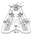
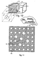
- Combinaison d'un système d'alignement optoélectronique et d'un dispositif pour étalonner ledit système d'alignement optoélectronique, la combinaison comprenant :au moins des premier et second dispositifs de contrôle optique espacés (122, 124) ;un processeur de données associé (32) conçu pour contrôler et déterminer les position et orientation par rapport auxdits dispositifs de contrôle de cibles apposées sur des objets tels que des roues de véhicules devant être alignées et, à partir de cette détermination, pour déduire les position et orientation des objets sur lesquels les cibles sont apposées ;des première et seconde cibles (164, 162) ayant chacune des particularités géométriques prédéterminées qui peuvent être détectées optiquement ;une poutre allongée (166, 167) pour supporter lesdites première et seconde cibles (164, 162) dans une disposition rigide l'une par rapport à l'autre et à une distance fixe prédéterminée l'une de l'autre de sorte que quand ladite poutre allongée (166, 167) est disposée par rapport à une surface de travail telle qu'à la fois les première et seconde cibles (164, 162) sont placées à l'intérieur du champ de visée dudit premier dispositif de contrôle (122), le système d'alignement est disposé pour contrôler optiquement les cibles (164, 162) afin d'obtenir la première information optique utile pour déterminer les position et orientation de chaque dite cible (164, 162) par rapport audit premier dispositif de contrôle (122) et quand ladite poutre allongée (166, 167) est réorientée de sorte que ladite première cible (164) est placée à l'intérieur du champ de visée dudit premier dispositif de contrôle (122) et ladite seconde cible (162) est placée à l'intérieur du champ de visée dudit second dispositif de contrôle (124), le système d'alignement est disposé pour contrôler optiquement les cibles (164, 162) afin d'obtenir la seconde information optique utile pour déterminer les position et orientation présentes de ladite première cible (164) par rapport audit premier dispositif de contrôle (122) et les position et orientation présentes de ladite seconde cible (162) par rapport audit second dispositif de contrôle (124) et le système d'alignement étant disposé pour utiliser les première et seconde informations optiques pour calculer les position et orientation précises dudit second dispositif de contrôle (124) par rapport audit premier dispositif de contrôle (122).
- Combinaison telle qu'exposée dans la revendication 1, dans laquelle lesdites cibles (164, 162) ont des faces qui sont planes et sont orientées suivant des angles prédéterminés par rapport à la longueur de ladite poutre (166, 167).
- Combinaison telle qu'exposée dans la revendication 2, dans laquelle chaque dite face cible est orientée suivant un angle de 45° par rapport à la longueur de ladite poutre (166, 167).
- Combinaison telle qu'exposée dans la revendication 1, dans laquelle il est proposé en outre des moyens de support (168, 169) pour supporter ladite poutre (166, 167) à une élévation prédéterminée au-dessus d'une surface de travail desdits moyens de support (168, 169) incluant une paire de jambes de support orientées verticalement ayant une extrémité apposée de manière rigide sur ladite poutre (166, 167) et des extrémités opposées apposées sur les moyens de base (170, 172) conçus pour supporter ladite poutre (166, 167) et les moyens de cible apposés (164, 162).
- Combinaison telle qu'exposée dans la revendication 1, dans laquelle lesdits premier et second moyens de cible (164, 162) sont tous deux disposés sur un côté de ladite poutre (166, 167).
- Combinaison telle qu'exposée dans la revendication 1, dans laquelle ladite poutre (166, 167) est un mécanisme en deux parties ayant une partie pouvant être reçue de manière télescopique à l'intérieur de l'autre de façon à être repliée de manière télescopique aux fins de rangement et extensible de manière télescopique aux fins d'usage d'étalonnage.
- Procédé d'étalonnage d'un système d'alignement optoélectronique incluant au moins des premier et second dispositifs de contrôle optique espacés (122, 124) et un processeur de données associé (117) conçu pour contrôler et déterminer les position et orientation par rapport auxdits dispositifs de contrôle de cibles (54) apposées sur des objets tels que des roues de véhicules (22L, 22R, 24L, 24R) devant être alignées et, à partir de cette détermination, pour déduire les position et orientation des objets (22L, 22R, 24L, 24R) sur lesquels les cibles (54) sont apposées, comprenant les étapes qui consistent à :procurer les premier et second moyens de cible (164, 162) ;procurer un moyen (168, 169) pour supporter lesdits premier et second moyens de cible (164, 162) dans une disposition rigide l'un par rapport à l'autre et à une distance fixe prédéterminée l'un de l'autre ;disposer lesdits moyens de support (168, 169) par rapport à une surface de travail de sorte que lesdits premier et second moyens de cible (164, 162) sont tous deux placés à l'intérieur du champ de visée dudit premier dispositif de contrôle (122) ;contrôler optiquement lesdits premier et second moyens de cible (168, 169) pour obtenir la première information optique utile pour déterminer les position et orientation de chacun desdits moyens de cible (168, 169) par rapport audit premier dispositif de contrôle (122) ;réorienter lesdits moyens de support (168, 169) de sorte que ledit premier moyen de cible (164) est placé à l'intérieur du champ de visée dudit premier dispositif de contrôle (122) et ledit second moyen de cible (162) est placé à l'intérieur du champ de visée dudit second dispositif de contrôle (124) et contrôler à nouveau optiquement lesdits premier et second moyens de cible (164, 162) pour obtenir une seconde information optique utile pour déterminer les position et orientation présentes dudit premier moyen de cible (164) par rapport audit premier dispositif de contrôle (122) et les position et orientation présentes dudit second moyen de cible (162) par rapport audit second dispositif de contrôle (124) etutiliser les première et seconde informations optiques pour calculer les position et orientation précises dudit second dispositif de contrôle (124) par rapport audit premier moyen de contrôle (122).
- Procédé tel qu'exposé dans la revendication 7, dans lequel lesdits premier et second moyen de cible (164, 162) ont des faces cibles qui sont généralement planes et ont une orientation angulaire prédéterminée par rapport auxdits moyens de support (168, 169).
- Procédé tel qu'exposé dans la revendication 8, dans lequel chaque dite face cible est orientée à 45° par rapport à une ligne imaginaire reliant lesdits premier et second moyens de cible (164, 162).
Applications Claiming Priority (3)
| Application Number | Priority Date | Filing Date | Title |
|---|---|---|---|
| US716585 | 1996-09-18 | ||
| US08/716,585 US5809658A (en) | 1993-09-29 | 1996-09-18 | Method and apparatus for calibrating cameras used in the alignment of motor vehicle wheels |
| PCT/US1997/016381 WO1998012503A1 (fr) | 1996-09-18 | 1997-09-11 | Etalonnage de cameras utilisees dans le reglage de la geometrie |
Publications (3)
| Publication Number | Publication Date |
|---|---|
| EP0927335A1 EP0927335A1 (fr) | 1999-07-07 |
| EP0927335A4 EP0927335A4 (fr) | 2000-11-22 |
| EP0927335B1 true EP0927335B1 (fr) | 2003-04-16 |
Family
ID=24878611
Family Applications (1)
| Application Number | Title | Priority Date | Filing Date |
|---|---|---|---|
| EP97942498A Expired - Lifetime EP0927335B1 (fr) | 1996-09-18 | 1997-09-11 | Etalonnage de cameras utilisees dans le reglage de la geometrie de roues |
Country Status (9)
| Country | Link |
|---|---|
| US (1) | US5809658A (fr) |
| EP (1) | EP0927335B1 (fr) |
| JP (1) | JP3454433B2 (fr) |
| KR (1) | KR100367124B1 (fr) |
| AU (1) | AU713446B2 (fr) |
| BR (1) | BR9711500A (fr) |
| CA (1) | CA2266071A1 (fr) |
| DE (2) | DE927335T1 (fr) |
| WO (1) | WO1998012503A1 (fr) |
Cited By (2)
| Publication number | Priority date | Publication date | Assignee | Title |
|---|---|---|---|---|
| DE102006041822A1 (de) * | 2006-09-06 | 2008-03-27 | Beissbarth Gmbh | Verfahren zur Fahrwerksmessung eines Kraftfahrzeugs, Fahrwerksvermessungseinrichtung sowie Kraftfahrzeugprüfstrasse |
| CN102883988A (zh) * | 2010-02-12 | 2013-01-16 | 实耐宝公司 | 用于将车辆引导至服务升降机上的装置 |
Families Citing this family (88)
| Publication number | Priority date | Publication date | Assignee | Title |
|---|---|---|---|---|
| US5724743A (en) * | 1992-09-04 | 1998-03-10 | Snap-On Technologies, Inc. | Method and apparatus for determining the alignment of motor vehicle wheels |
| US6259827B1 (en) | 1996-03-21 | 2001-07-10 | Cognex Corporation | Machine vision methods for enhancing the contrast between an object and its background using multiple on-axis images |
| US6075881A (en) | 1997-03-18 | 2000-06-13 | Cognex Corporation | Machine vision methods for identifying collinear sets of points from an image |
| US6405111B2 (en) * | 1997-05-16 | 2002-06-11 | Snap-On Technologies, Inc. | System and method for distributed computer automotive service equipment |
| US6608647B1 (en) | 1997-06-24 | 2003-08-19 | Cognex Corporation | Methods and apparatus for charge coupled device image acquisition with independent integration and readout |
| US5978521A (en) * | 1997-09-25 | 1999-11-02 | Cognex Corporation | Machine vision methods using feedback to determine calibration locations of multiple cameras that image a common object |
| US6381375B1 (en) | 1998-02-20 | 2002-04-30 | Cognex Corporation | Methods and apparatus for generating a projection of an image |
| US6381366B1 (en) | 1998-12-18 | 2002-04-30 | Cognex Corporation | Machine vision methods and system for boundary point-based comparison of patterns and images |
| US6687402B1 (en) | 1998-12-18 | 2004-02-03 | Cognex Corporation | Machine vision methods and systems for boundary feature comparison of patterns and images |
| US7982725B2 (en) * | 1999-05-25 | 2011-07-19 | Silverbrook Research Pty Ltd | Sensing device with inductive charging |
| DE19934864A1 (de) | 1999-07-24 | 2001-02-08 | Bosch Gmbh Robert | Vorrichtung zum Bestimmen der Rad- und/oder Achsgeometrie von Kraftfahrzeugen |
| JP3827480B2 (ja) * | 1999-08-13 | 2006-09-27 | 日立建機株式会社 | 自動運転建設機械およびその位置計測手段の校正方法 |
| US6237234B1 (en) | 1999-09-28 | 2001-05-29 | Snap-On Technologies, Inc. | Method and apparatus for measuring vehicle wheel roll radius |
| US6684402B1 (en) | 1999-12-01 | 2004-01-27 | Cognex Technology And Investment Corporation | Control methods and apparatus for coupling multiple image acquisition devices to a digital data processor |
| US6323776B1 (en) | 1999-12-21 | 2001-11-27 | Snap-On Technologies, Inc. | Method and apparatus of automatically identifying faults in a machine vision measuring system |
| US6498959B1 (en) | 2000-01-19 | 2002-12-24 | Hunter Engineering Company | Apparatus and method for controlling a mechanism for positioning video cameras for use in measuring vehicle wheel alignment |
| JP4849757B2 (ja) * | 2000-03-23 | 2012-01-11 | スナップ − オン テクノロジーズ,インコーポレイテッド | 自己校正するマルチカメラ機械視覚測定システム |
| US6748104B1 (en) | 2000-03-24 | 2004-06-08 | Cognex Corporation | Methods and apparatus for machine vision inspection using single and multiple templates or patterns |
| US6560883B2 (en) * | 2000-06-28 | 2003-05-13 | Snap-On Technologies, Inc. | Method and system for conducting wheel alignment |
| CN1306246C (zh) | 2000-08-14 | 2007-03-21 | 捷装技术公司 | 用于机动车辆车轮对准的自校准三维机器测量系统 |
| US6556971B1 (en) * | 2000-09-01 | 2003-04-29 | Snap-On Technologies, Inc. | Computer-implemented speech recognition system training |
| US6965324B1 (en) * | 2000-10-21 | 2005-11-15 | Robert W. Suggs, Sr. | Automotive picture and data acquisition center and method |
| US6594007B2 (en) | 2001-02-01 | 2003-07-15 | Snap-On Technologies, Inc. | Method and apparatus for mapping system calibration |
| WO2002103286A1 (fr) * | 2001-06-15 | 2002-12-27 | Snap-On Technologies, Inc. | Systeme de determination de position d'etalonnage automatique |
| WO2003002937A1 (fr) * | 2001-06-28 | 2003-01-09 | Snap-On Technologies, Inc. | Systeme auto-etalonne de determination de position, et interface utilisateur |
| US6661505B2 (en) | 2001-06-28 | 2003-12-09 | Snap-On Technologies, Inc. | Method and system for measuring caster trail |
| US7062861B2 (en) * | 2001-06-28 | 2006-06-20 | Snap-On Incorporated | Self-calibrating position determination system and user interface |
| US20030035138A1 (en) * | 2001-08-17 | 2003-02-20 | Schilling Mary K. | Internet-based custom package-printing process |
| US7302093B2 (en) * | 2002-03-26 | 2007-11-27 | Hunter Engineering Company | Color vision vehicle wheel alignment system |
| DE10229336A1 (de) * | 2002-06-29 | 2004-01-15 | Robert Bosch Gmbh | Verfahren und Vorrichtung zur Kalibrierung von Bildsensorsystemen |
| US7209161B2 (en) * | 2002-07-15 | 2007-04-24 | The Boeing Company | Method and apparatus for aligning a pair of digital cameras forming a three dimensional image to compensate for a physical misalignment of cameras |
| AU2003254228A1 (en) * | 2002-07-25 | 2004-04-19 | Snap-On Technologies, Inc. | Diagnosing malfunctioning wheel alignment system |
| US6728609B2 (en) | 2002-09-16 | 2004-04-27 | Snap-On Technologies, Inc. | Diagnostic method and system for a multiple-link steering system |
| US6823601B2 (en) * | 2002-09-17 | 2004-11-30 | Snap-On Incorporated | Apparatus for use with a 3D image wheel aligner for facilitating adjustment of an adaptive cruise control sensor on a motor vehicle |
| US20040172170A1 (en) * | 2002-12-02 | 2004-09-02 | Lesert Brooks R. | Portable wheel alignment device |
| US6871409B2 (en) | 2002-12-18 | 2005-03-29 | Snap-On Incorporated | Gradient calculating camera board |
| DE10259954A1 (de) * | 2002-12-20 | 2004-07-01 | Robert Bosch Gmbh | Vorrichtung zur Bestimmung der Rad- und/oder Achsgeometrie von Kraftfahrzeugen |
| CN1742193B (zh) * | 2003-01-27 | 2010-04-28 | 斯耐普昂技术有限公司 | 车轮定位设备的校准检定 |
| US7121011B2 (en) * | 2003-05-09 | 2006-10-17 | Snap-On Incorporated | Camera technique for adaptive cruise control (ACC) sensor adjustment |
| US7415324B2 (en) * | 2003-07-31 | 2008-08-19 | Snap-On Incorporated | Vehicle wheel alignment adjustment method |
| WO2005012831A1 (fr) * | 2003-07-31 | 2005-02-10 | Snap-On Incorporated | Procede de reglage d'alignement de deux roues |
| US20050038580A1 (en) * | 2003-08-15 | 2005-02-17 | Seim Kerri Jean | Information about structural integrity of vehicles |
| US20050060899A1 (en) * | 2003-09-23 | 2005-03-24 | Snap-On Technologies, Inc. | Invisible target illuminators for 3D camera-based alignment systems |
| US7164472B2 (en) * | 2003-10-09 | 2007-01-16 | Hunter Engineering Company | Common reference target machine vision wheel alignment system |
| CN101124454A (zh) * | 2004-12-30 | 2008-02-13 | 斯耐普昂公司 | 非接触式车辆测量方法及系统 |
| ITRE20050043A1 (it) * | 2005-04-26 | 2006-10-27 | Corghi Spa | Metodo e dispositivo per determinare l'assetto delle ruote di un veicolo |
| DE602006007700D1 (de) * | 2005-05-13 | 2009-08-20 | Snap On Tools Corp | Befestigungssystem für das messmodul eines radausrichtungsgerätes |
| US20070040065A1 (en) * | 2005-08-19 | 2007-02-22 | Von Thal German | Flexible refueling boom extendable tube |
| US7444752B2 (en) | 2005-09-28 | 2008-11-04 | Hunter Engineering Company | Method and apparatus for vehicle service system optical target |
| US8111904B2 (en) | 2005-10-07 | 2012-02-07 | Cognex Technology And Investment Corp. | Methods and apparatus for practical 3D vision system |
| US8162584B2 (en) | 2006-08-23 | 2012-04-24 | Cognex Corporation | Method and apparatus for semiconductor wafer alignment |
| DE102006058383A1 (de) * | 2006-12-08 | 2008-06-12 | Robert Bosch Gmbh | Verfahren zur optischen Fahrwerksvermessung |
| US8132759B2 (en) * | 2007-03-21 | 2012-03-13 | The Boeing Company | System and method for facilitating aerial refueling |
| US7959110B2 (en) * | 2007-04-11 | 2011-06-14 | The Boeing Company | Methods and apparatus for resisting torsional loads in aerial refueling booms |
| US7424387B1 (en) | 2007-04-18 | 2008-09-09 | Snap-On Incorporated | Method for use with an optical aligner system for positioning a fixture relative to a vehicle |
| WO2008143614A1 (fr) | 2007-05-21 | 2008-11-27 | Snap-On Incorporated | Procédé et appareil d'alignement de roues |
| US7953247B2 (en) * | 2007-05-21 | 2011-05-31 | Snap-On Incorporated | Method and apparatus for wheel alignment |
| US7870677B2 (en) * | 2007-05-31 | 2011-01-18 | Snap-On Incorporated | Lightweight wheel clamp for vehicle wheel alignment system |
| US7640673B2 (en) * | 2007-08-01 | 2010-01-05 | Snap-On Incorporated | Calibration and operation of wheel alignment systems |
| US7855783B2 (en) * | 2007-09-18 | 2010-12-21 | Snap-On Incorporated | Integrated circuit image sensor for wheel alignment systems |
| DE102008042024A1 (de) * | 2008-09-12 | 2010-03-18 | Robert Bosch Gmbh | Verfahren und Vorrichtung zur optischen Achsvermessung von Kraftfahrzeugen |
| CN101726420B (zh) * | 2009-11-15 | 2011-09-07 | 吉林大学 | 三自由度车轮定位仪靶标 |
| WO2011075192A2 (fr) * | 2009-12-18 | 2011-06-23 | Snap-On Incorporated | Bride légère de roue pour système d'alignement de roue de véhicule |
| IT1399988B1 (it) * | 2010-05-05 | 2013-05-09 | Space S R L Con Unico Socio | Sistema, e relativo metodo, di determinazione dell'allineamento delle ruote di un veicolo |
| DE102010040637A1 (de) * | 2010-09-13 | 2012-03-15 | Robert Bosch Gmbh | Verfahren zum Kalibrieren eines Messwertaufnehmers |
| IT1404235B1 (it) * | 2010-12-30 | 2013-11-15 | Space S R L Con Unico Socio | Dispositivo di rilevamento, e relativo sistema di determinazione dell'orientamento delle ruote di un veicolo |
| CN102589903A (zh) * | 2011-12-22 | 2012-07-18 | 上海一成汽车检测设备科技有限公司 | 汽车3d四轮定位仪晨检装置及其方法 |
| US9644952B2 (en) * | 2012-10-18 | 2017-05-09 | Hunter Engineering Company | Method for evaluating component calibration in machine vision vehicle wheel alignment system |
| KR101461423B1 (ko) | 2013-04-17 | 2014-11-20 | 장철환 | 타이어 얼라인먼트 검출장치 |
| KR101510336B1 (ko) * | 2013-11-14 | 2015-04-07 | 현대자동차 주식회사 | 차량용 운전자 지원 시스템의 검사 장치 |
| KR101510338B1 (ko) * | 2013-11-22 | 2015-04-07 | 현대자동차 주식회사 | 차량용 차선 이탈 경보 시스템의 검사 장치 |
| DE102014204691A1 (de) * | 2014-03-13 | 2015-09-17 | Robert Bosch Gmbh | Bildaufnahmevorrichtung, insbesondere zur Fahrzeugvermessung |
| EP3234502A4 (fr) | 2014-12-17 | 2018-08-15 | Snap-On Incorporated | Mesure de hauteur de conduite en temps réel |
| EP4257919A3 (fr) * | 2015-01-07 | 2023-10-18 | Snap-on Incorporated | Étalonnage d'axe de roue virtuel en roulement |
| CN105823471B (zh) * | 2015-01-28 | 2020-03-17 | 株式会社拓普康 | 三维位置计测系统 |
| DE102015209246A1 (de) * | 2015-05-20 | 2016-11-24 | Robert Bosch Gmbh | System und Verfahren zur Durchführung von Einstellarbeiten an einem Kraftfahrzeug |
| KR101541013B1 (ko) | 2015-06-03 | 2015-08-04 | 삼홍엔지니어링 주식회사 | 휠 얼라인먼트 캘리브레이션 방법, 및 이에 적용되는 각도 및 길이 조절이 가능한 캘리브레이션 바 |
| JP6484515B2 (ja) * | 2015-07-09 | 2019-03-13 | 株式会社日立製作所 | 油入機器の漏油検出装置 |
| JP6658054B2 (ja) * | 2016-02-16 | 2020-03-04 | トヨタ車体株式会社 | 車体部品の施工部位判定システム及び施工部位判定方法 |
| JP6500852B2 (ja) * | 2016-07-11 | 2019-04-17 | 株式会社安川電機 | ロボットシステム、ロボットの制御方法、ロボットコントローラ |
| DE112017004974T5 (de) * | 2016-09-30 | 2019-06-19 | Burke E. Porter Machinery Company | Radeinstellungsmessverfahren und System für Fahrzeugräder |
| CN108453646A (zh) * | 2018-04-20 | 2018-08-28 | 深圳市道通科技股份有限公司 | 装夹装置及汽车标定设备 |
| CN109059769B (zh) * | 2018-08-31 | 2020-08-28 | 中国科学院力学研究所 | 一种非接触式受电弓升降弓臂杆位置关系测量方法 |
| CN111521209A (zh) * | 2019-02-01 | 2020-08-11 | 深圳市道通科技股份有限公司 | 一种标定系统及其标定支架 |
| IT201900022944A1 (it) | 2019-12-04 | 2021-06-04 | Nexion Spa | Apparato e metodo per la rilevazione dell’assetto di un veicolo |
| JP7284118B2 (ja) * | 2020-03-11 | 2023-05-30 | 本田技研工業株式会社 | ターゲット設置装置 |
| JP2022111730A (ja) * | 2021-01-20 | 2022-08-01 | 本田技研工業株式会社 | ターゲット設置装置及びそれを用いたターゲット設置方法 |
| CN114878145B (zh) * | 2022-05-05 | 2023-01-03 | 中国科学院长春光学精密机械与物理研究所 | 一种基于温度畸变值评价光学传函影响的方法和系统 |
Family Cites Families (9)
| Publication number | Priority date | Publication date | Assignee | Title |
|---|---|---|---|---|
| US2292969A (en) * | 1939-12-20 | 1942-08-11 | Albert P Peters | Aligning device |
| US3288020A (en) * | 1963-01-08 | 1966-11-29 | Fmc Corp | Apparatus for optically measuring wheel alignment characteristics |
| US3501240A (en) * | 1966-09-09 | 1970-03-17 | Fmc Corp | Optical wheel alignment apparatus |
| DE2948573A1 (de) * | 1979-12-03 | 1981-06-04 | Siemens AG, 1000 Berlin und 8000 München | Verfahren und anordnung zur beruehrungslosen achsvermessung an kraftfahrzeugen |
| US4588194A (en) * | 1985-02-04 | 1986-05-13 | Steidle Daniel L | Target device with remote resetting means |
| US4726122A (en) * | 1986-11-03 | 1988-02-23 | Nicator Ab | Wheel alignment apparatus for vehicles |
| US5274433A (en) * | 1989-07-07 | 1993-12-28 | Miradco | Laser-based wheel alignment system |
| ATE203320T1 (de) * | 1992-09-04 | 2001-08-15 | Snap On Tech Inc | Verfahren und vorrichtung zur bestimmung der ausrichtung von kraftfahrzeugrädern |
| US5342062A (en) * | 1992-12-17 | 1994-08-30 | Lance Land & Livestock Ltd. | Gallery, silhouette, and target system which is easily resettable, collapsible, and portable |
-
1996
- 1996-09-18 US US08/716,585 patent/US5809658A/en not_active Expired - Lifetime
-
1997
- 1997-09-11 JP JP51481398A patent/JP3454433B2/ja not_active Expired - Lifetime
- 1997-09-11 AU AU44184/97A patent/AU713446B2/en not_active Expired
- 1997-09-11 DE DE0927335T patent/DE927335T1/de active Pending
- 1997-09-11 DE DE69721022T patent/DE69721022T2/de not_active Expired - Lifetime
- 1997-09-11 KR KR10-1999-7002282A patent/KR100367124B1/ko not_active IP Right Cessation
- 1997-09-11 EP EP97942498A patent/EP0927335B1/fr not_active Expired - Lifetime
- 1997-09-11 CA CA002266071A patent/CA2266071A1/fr not_active Abandoned
- 1997-09-11 WO PCT/US1997/016381 patent/WO1998012503A1/fr active IP Right Grant
- 1997-09-11 BR BR9711500-2A patent/BR9711500A/pt not_active Application Discontinuation
Cited By (3)
| Publication number | Priority date | Publication date | Assignee | Title |
|---|---|---|---|---|
| DE102006041822A1 (de) * | 2006-09-06 | 2008-03-27 | Beissbarth Gmbh | Verfahren zur Fahrwerksmessung eines Kraftfahrzeugs, Fahrwerksvermessungseinrichtung sowie Kraftfahrzeugprüfstrasse |
| CN102883988A (zh) * | 2010-02-12 | 2013-01-16 | 实耐宝公司 | 用于将车辆引导至服务升降机上的装置 |
| US9452917B2 (en) | 2010-02-12 | 2016-09-27 | Snap-On Incorporated | Apparatus for guiding a vehicle onto a service lift using a machine vision wheel alignment system |
Also Published As
| Publication number | Publication date |
|---|---|
| JP3454433B2 (ja) | 2003-10-06 |
| AU713446B2 (en) | 1999-12-02 |
| DE69721022T2 (de) | 2004-04-01 |
| KR20000036220A (ko) | 2000-06-26 |
| US5809658A (en) | 1998-09-22 |
| DE927335T1 (de) | 1999-12-09 |
| EP0927335A1 (fr) | 1999-07-07 |
| JP2001501730A (ja) | 2001-02-06 |
| CA2266071A1 (fr) | 1998-03-26 |
| WO1998012503A1 (fr) | 1998-03-26 |
| EP0927335A4 (fr) | 2000-11-22 |
| AU4418497A (en) | 1998-04-14 |
| KR100367124B1 (ko) | 2003-01-06 |
| DE69721022D1 (de) | 2003-05-22 |
| BR9711500A (pt) | 2001-11-20 |
Similar Documents
| Publication | Publication Date | Title |
|---|---|---|
| EP0927335B1 (fr) | Etalonnage de cameras utilisees dans le reglage de la geometrie de roues | |
| US5943783A (en) | Method and apparatus for determining the alignment of motor vehicle wheels | |
| EP0674759B1 (fr) | Procede et appareil de determination de l'alignement des roues d'une automobile | |
| US6532062B2 (en) | Method and apparatus for measuring vehicle wheel scrub radius | |
| US6894771B1 (en) | Wheel alignment apparatus and method utilizing three-dimensional imaging | |
| US7424387B1 (en) | Method for use with an optical aligner system for positioning a fixture relative to a vehicle | |
| US7369222B2 (en) | Wheel aligner measurement module attachment system | |
| US7336350B2 (en) | Wheel alignment apparatus and method utilizing three-dimensional imaging | |
| US6237234B1 (en) | Method and apparatus for measuring vehicle wheel roll radius | |
| US8638452B2 (en) | Measuring head for a chassis measuring system, chassis measuring system and method for determining the position parameters of measuring heads of a chassis measuring system | |
| US6526665B2 (en) | Glint-resistant position determination system | |
| AU669211C (en) | Method and apparatus for determining the alignment of motor vehicle wheels |
Legal Events
| Date | Code | Title | Description |
|---|---|---|---|
| PUAI | Public reference made under article 153(3) epc to a published international application that has entered the european phase |
Free format text: ORIGINAL CODE: 0009012 |
|
| 17P | Request for examination filed |
Effective date: 19990301 |
|
| AK | Designated contracting states |
Kind code of ref document: A1 Designated state(s): DE FR GB IT NL |
|
| ITCL | It: translation for ep claims filed |
Representative=s name: BOTTI &FERRARI S.R.L. |
|
| EL | Fr: translation of claims filed | ||
| DET | De: translation of patent claims | ||
| A4 | Supplementary search report drawn up and despatched |
Effective date: 20001006 |
|
| AK | Designated contracting states |
Kind code of ref document: A4 Designated state(s): DE FR GB IT NL |
|
| 17Q | First examination report despatched |
Effective date: 20010914 |
|
| GRAH | Despatch of communication of intention to grant a patent |
Free format text: ORIGINAL CODE: EPIDOS IGRA |
|
| GRAH | Despatch of communication of intention to grant a patent |
Free format text: ORIGINAL CODE: EPIDOS IGRA |
|
| GRAA | (expected) grant |
Free format text: ORIGINAL CODE: 0009210 |
|
| AK | Designated contracting states |
Designated state(s): DE FR GB IT NL |
|
| PG25 | Lapsed in a contracting state [announced via postgrant information from national office to epo] |
Ref country code: NL Free format text: LAPSE BECAUSE OF FAILURE TO SUBMIT A TRANSLATION OF THE DESCRIPTION OR TO PAY THE FEE WITHIN THE PRESCRIBED TIME-LIMIT Effective date: 20030416 |
|
| REG | Reference to a national code |
Ref country code: GB Ref legal event code: FG4D |
|
| REF | Corresponds to: |
Ref document number: 69721022 Country of ref document: DE Date of ref document: 20030522 Kind code of ref document: P |
|
| NLV1 | Nl: lapsed or annulled due to failure to fulfill the requirements of art. 29p and 29m of the patents act | ||
| ET | Fr: translation filed | ||
| PLBE | No opposition filed within time limit |
Free format text: ORIGINAL CODE: 0009261 |
|
| STAA | Information on the status of an ep patent application or granted ep patent |
Free format text: STATUS: NO OPPOSITION FILED WITHIN TIME LIMIT |
|
| 26N | No opposition filed |
Effective date: 20040119 |
|
| REG | Reference to a national code |
Ref country code: FR Ref legal event code: PLFP Year of fee payment: 20 |
|
| PGFP | Annual fee paid to national office [announced via postgrant information from national office to epo] |
Ref country code: GB Payment date: 20160927 Year of fee payment: 20 |
|
| PGFP | Annual fee paid to national office [announced via postgrant information from national office to epo] |
Ref country code: FR Payment date: 20160926 Year of fee payment: 20 |
|
| PGFP | Annual fee paid to national office [announced via postgrant information from national office to epo] |
Ref country code: DE Payment date: 20160928 Year of fee payment: 20 |
|
| PGFP | Annual fee paid to national office [announced via postgrant information from national office to epo] |
Ref country code: IT Payment date: 20160923 Year of fee payment: 20 |
|
| REG | Reference to a national code |
Ref country code: DE Ref legal event code: R071 Ref document number: 69721022 Country of ref document: DE |
|
| REG | Reference to a national code |
Ref country code: GB Ref legal event code: PE20 Expiry date: 20170910 |
|
| PG25 | Lapsed in a contracting state [announced via postgrant information from national office to epo] |
Ref country code: GB Free format text: LAPSE BECAUSE OF EXPIRATION OF PROTECTION Effective date: 20170910 |