EP0927335B1 - Kalibrierung von kameras bei anwendung in radjustierung - Google Patents
Kalibrierung von kameras bei anwendung in radjustierung Download PDFInfo
- Publication number
- EP0927335B1 EP0927335B1 EP97942498A EP97942498A EP0927335B1 EP 0927335 B1 EP0927335 B1 EP 0927335B1 EP 97942498 A EP97942498 A EP 97942498A EP 97942498 A EP97942498 A EP 97942498A EP 0927335 B1 EP0927335 B1 EP 0927335B1
- Authority
- EP
- European Patent Office
- Prior art keywords
- target
- orientation
- relative
- targets
- wheel
- Prior art date
- Legal status (The legal status is an assumption and is not a legal conclusion. Google has not performed a legal analysis and makes no representation as to the accuracy of the status listed.)
- Expired - Lifetime
Links
Images


Classifications
-
- G—PHYSICS
- G01—MEASURING; TESTING
- G01B—MEASURING LENGTH, THICKNESS OR SIMILAR LINEAR DIMENSIONS; MEASURING ANGLES; MEASURING AREAS; MEASURING IRREGULARITIES OF SURFACES OR CONTOURS
- G01B11/00—Measuring arrangements characterised by the use of optical techniques
- G01B11/26—Measuring arrangements characterised by the use of optical techniques for measuring angles or tapers; for testing the alignment of axes
- G01B11/275—Measuring arrangements characterised by the use of optical techniques for measuring angles or tapers; for testing the alignment of axes for testing wheel alignment
- G01B11/2755—Measuring arrangements characterised by the use of optical techniques for measuring angles or tapers; for testing the alignment of axes for testing wheel alignment using photoelectric detection means
-
- G—PHYSICS
- G01—MEASURING; TESTING
- G01B—MEASURING LENGTH, THICKNESS OR SIMILAR LINEAR DIMENSIONS; MEASURING ANGLES; MEASURING AREAS; MEASURING IRREGULARITIES OF SURFACES OR CONTOURS
- G01B2210/00—Aspects not specifically covered by any group under G01B, e.g. of wheel alignment, caliper-like sensors
- G01B2210/10—Wheel alignment
- G01B2210/12—Method or fixture for calibrating the wheel aligner
-
- G—PHYSICS
- G01—MEASURING; TESTING
- G01B—MEASURING LENGTH, THICKNESS OR SIMILAR LINEAR DIMENSIONS; MEASURING ANGLES; MEASURING AREAS; MEASURING IRREGULARITIES OF SURFACES OR CONTOURS
- G01B2210/00—Aspects not specifically covered by any group under G01B, e.g. of wheel alignment, caliper-like sensors
- G01B2210/10—Wheel alignment
- G01B2210/14—One or more cameras or other optical devices capable of acquiring a two-dimensional image
- G01B2210/143—One or more cameras on each side of a vehicle in the main embodiment
-
- G—PHYSICS
- G01—MEASURING; TESTING
- G01B—MEASURING LENGTH, THICKNESS OR SIMILAR LINEAR DIMENSIONS; MEASURING ANGLES; MEASURING AREAS; MEASURING IRREGULARITIES OF SURFACES OR CONTOURS
- G01B2210/00—Aspects not specifically covered by any group under G01B, e.g. of wheel alignment, caliper-like sensors
- G01B2210/10—Wheel alignment
- G01B2210/26—Algorithms, instructions, databases, computerized methods and graphical user interfaces employed by a user in conjunction with the wheel aligner
-
- G—PHYSICS
- G01—MEASURING; TESTING
- G01B—MEASURING LENGTH, THICKNESS OR SIMILAR LINEAR DIMENSIONS; MEASURING ANGLES; MEASURING AREAS; MEASURING IRREGULARITIES OF SURFACES OR CONTOURS
- G01B2210/00—Aspects not specifically covered by any group under G01B, e.g. of wheel alignment, caliper-like sensors
- G01B2210/10—Wheel alignment
- G01B2210/30—Reference markings, reflector, scale or other passive device
- G01B2210/303—Reference markings, reflector, scale or other passive device fixed to the ground or to the measuring station
Definitions
- This invention relates generally to a method and apparatus for calibrating electronic cameras, and more particularly to a method and apparatus for determining the spacial position and relative orientation of a pair of electronic cameras used to optically determine the alignment of motor vehicle wheels.
- Camber is the angle representing the inward or outward tilt from true vertical of the wheel and is positive if the top of the wheel tilts outward.
- Caster is the angle representing the forward or rearward tilt from true vertical of the steering axis. When a wheel is viewed from the side, the angle is positive when the upper ball joint (or top of king pin, or upper mount of a McPherson strut) is rearward of the lower ball joint (or bottom of the king pin, or lower mount of a McPherson strut).
- Thrust Line is a line that bisects the angle formed by the rear toe lines. Lines and angles measured clockwise from the 12:00 axis are positive.
- Geometric Center Line is the line that runs from a point on the rear axle midway between the rear wheels to a point on the front axle midway between the front wheels.
- Angles pertaining to the left side are positive when clockwise of the thrust line and angles pertaining to the right side are positive when counterclockwise of the thrust line.
- Offset is the amount that a front wheel and its corresponding rear wheel are out of line with each other. If there is no offset, the rear wheel is directly behind the front wheel.
- Setback is the amount that one wheel on one side of the vehicle is displaced back from its corresponding wheel on the other side of the vehicle.
- Steering Axis is a line projected from the upper pivot point of the upper ball joint or top of kingpin, or McPherson strut, through the lower ball joint.
- SAI Steering Axis Inclination
- KPI kingpin inclination
- Thrust Angle is the angle between the thrust line and the geometric center line. Angles measured clockwise from the geometric center line are positive.
- Total Toe is the sum of individual, side-by-side toe measurements. If lines projected parallel to the primary planes of the wheels intersect at a point ahead of the side-by-side wheels, the angle is positive (toe in). If the lines would intersect behind the side to side wheels, the angle is negative (toe out). If the projected lines are parallel, the toe is zero.
- the Camber and Toe measurements for each wheel of the vehicle are relative measurements i.e. relative to' a vertical plane or to another wheel and these measurements are therefore made when the wheels are stationary.
- the calculation of Caster and SAI is a dynamic procedure and entails determining how the Camber of the front wheels changes with respect to a change in steering angle. This is usually done by swinging the front wheels from left to right through an angle of between 10° and 30°, or vice versa, while determining the resultant changes in Camber of the wheel with steering angle changes. From these determinations the Caster and SAI are determined by methods well known in the wheel alignment industry.
- the wheels of a motor vehicle need to be periodically checked to determine whether or not they are in alignment with each other because, if any of the wheels are out of alignment, this can result in excessive or uneven wear of the tires of the vehicle and/or adversely affect the handling and stability of the vehicle.
- All these devices operate with an apparatus which is mounted onto the wheel of a vehicle and which emits or reflects a light beam to illuminate an area on some form of reference such as a reference grid.
- a reference grid As the position of the area illuminated by the beam on the reference is a function of the deflection of the beam, which in turn is a function of the orientation of the wheel, the alignment of the wheel can be calculated from the positioning of the illuminated area on the reference.
- Other devices utilize a measuring head mounted onto each wheel of the vehicle.
- These heads typically include gravity gauges that are either connected to adjacent heads by means of cords or wires under tension or, alternatively, configured with beams of light shining between adjacent heads.
- the measuring heads which must be maintained level, are then able to measure the relative angles between adjacent cords/beams of light as well as the angles between each wheel and its adjacent cord/beam of light and, from these measurements, calculate the alignment of the wheels.
- the heads used in the above described wheel alignment devices are delicate and expensive, complicated to use and must be carefully set up. Furthermore, certain of these devices rely on the accurate placing of optical or other measuring devices either on or in a set position relative to the wheels of the vehicle. This can be time consuming and complicated for the technicians operating the alignment determination apparatus.
- Such equipment also has the disadvantage that components which are carelessly left secured to the wheels when the vehicle is moved from the test area can very easily be damaged. Such damage, particularly in the case of sophisticated equipment, can be costly.
- German patent application DE 29 48 573 in the name of Siemens Aktiengesellschaft discloses an apparatus which can be used to determine both the orientation and the spatial position of the plane of the wheel of a motor vehicle as well as the three-dimensional position of the steering axis of this wheel.
- the application discloses a method whereby a television camera takes an image of the rim on the wheel from two different known height positions. These images are fed into a processor which relates them to the known coordinates and viewing angles of the camera at its two height positions and determines the three-dimensional position of the rim.
- the method and apparatus of the described application has the disadvantage that, because a triangulation technique is used, at least two images (from different cameras or from a single camera viewing along different axes) of the wheel must be taken. Furthermore, both the coordinated three-dimensional position for each point from where an image of the wheel is taken as well as the orientation of each of the view paths must be accurately known.
- a further disadvantage is that the method does not indicate how it makes allowances for the perspective distortion of the image of the rim of the wheel.
- This perspective distortion causes the image of the rim to be in the form of a distorted ellipse with the edge of the ellipse closest to the television camera appearing larger and the image of the edge furthest from the camera appearing smaller. If allowance for this distortion is not made, inaccuracies can result.
- US 4,726,122 discloses an apparatus for measuring the wheel alignment of the wheels of vehicles comprising a target provided with a plurality of scales for accomplishing the measurements.
- the target is pivotally attached to a support shaft of a target support structure wherein the target can be positioned in arbitrary locations around the shaft.
- a line of sight from a sighting instrument can be directed to impinge on the respective scales of the target facing the instrument.
- Another object of this invention is to provide a method and apparatus for calibrating wheel alignment apparatus that uses an opto-electronic image detection device to determine the alignment of vehicle wheels.
- a further object of the present invention is to provide a rigid target structure that can be variously positioned in front of a dual camera image detection apparatus and used in association therewith to determine the spatial position and relative orientations of the cameras.
- an opto-electronic alignment system and an apparatus for calibrating said opto-electronic alignment system.
- This combination which is defined in claim 1 comprises: at least first and second spaced apart optical inspection devices; an associated data processor adapted to inspect and determine the position and orientation relative to said inspection devices of targets affixed to objects such as vehicle wheels to be aligned, and from such determination to infer the position and orientation of the objects to which the targets are affixed; first and second targets each having predetermined geometric attributes that can be optically detected; an elongated beam for supporting said first and second targets in rigid position relative to each other and at a predetermined fixed distance from each other so that when said elongated beam is disposed relative to a work surface such that both said first and second targets lie within the field of view of said first inspection device, the alignment system is arranged to optically inspect the targets to obtain first optical information useful to determine the position and orientation of each said target relative to said first inspection device, and when said elongated beam is reoriented
- a presently preferred embodiment of this invention includes a rigid frame to which is mounted a pair of specially configured targets.
- the assembly is adapted for placement with the field(s) of view of at least one of a pair of electronic cameras forming a part of an opto-electronic alignment system.
- the viewing camera(s) forms perspective images of each target, and electronic signals corresponding to each of the images are transferred to an electronic processing means which correlates the perspective image of each of the targets with the true shape of each target.
- the processor relates the dimensions of certain known geometric elements of the target with the dimensions of corresponding elements in the perspective image and by performing certain trigonometric calculations (or by any other suitable mathematical or numerical methods), calculates the position of each target relative to the viewing camera(s).
- the processing means can determine the position and orientation of each camera relative to the other. With such information recorded, the system is "calibrated".
- Figures 12a-d, 13, and 14 are embodiments according to the present invention.
- Figures 1 to 11 are not according to the present invention but are included in the present patent application for clarity as they are useful for understanding the invention and contain features which may be used in the invention.
- FIGS. 1a - 1c are diagrams illustrating three different images of a circle resulting from various degrees of rotation abount different axes ;
- FIG. 2 is a schematic representation illustrating a single camera system used to inspect the alignment of motor vehicle wheels
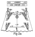
- PIG. 2a is an illustration of a quasi three-dimensional representation of a type that may be generated on a system display screen to report detected alignment and to guide the technician in making appropriate vehicle adjustments;
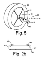
- FIG. 2b is a cross-section through a pan-and-tilt mirror used in one illustrated target
- FIG. 3 is a representation of an exemplary target face design that can be used with the apparatus in FIG. 2;
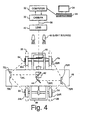
- FIG. 4 is a schematic representation of an alternative embodiment of a single camera apparatus
- FIG. 5 is a perspective view of an alternative target design mounted on a vehicle wheel
- FIG. 6 is a schematic representation of an image of the targets illustrated in FIG. 5 formed using the optical system of FIG. 4;
- FIG. 7 illustrates, one method of how the apparatus calculates the run-out factor of the wheel
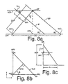
- FIGS. 8a-8c illustrate certain aspects of the mathematics performed in the method and apparatus
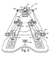
- FIG. 9 is a diagram schematically illustrating a dual camera arrangement of an alignment system of the type described.
- FIG. 10 illustrates details of the camera/light subsystem of FIG. 9
- FIG. 11 illustrates an alternative arrangement of a target array
- FIGS. 12a-12d are respectively side, top, front and back views of a target assembly in accordance with the present invention.
- FIGS. 13 and 14 are perspective views showing the positioning of the assembly of FIGS. 12a-12d relative to dual cameras in implementing the method of the present invention.
- This system is based on the fact that the image of a body varies according to the perspective from which such body is viewed and that the variation in the image is directly related to and determinable from the perspective angle of the view path along which the body is viewed.
- FIGS. 1(a)-(c) This is illustrated in FIGS. 1(a)-(c) with reference to a circle 10, shown as it would appear if viewed from three different perspectives.
- the circle 10 is illustrated as it would appear if it were viewed along an axis perpendicular t'o its primary plane which, in this case, is in the plane of the paper. If this circle is rotated through an angle ⁇ , being less than 90°, about the y-axis 12 and viewed along the same view path, the image of the circle 10 will be that of an ellipse as shown in FIG. 1(b).
- FIG. 1(c) the image of the circle (the ellipse) will be as shown in FIG. 1(c), in which the major axis 16 of the ellipse is shown to be angled relative to both the x and y-axes.
- these orientation calculations are done by applying trigonometric functions or any other mathematical/numerical methods to the ratios between the minor and/or major axis and the diameter.
- the angles of the minor and major axes to the horizontal (x-) axis or vertical (y-) axis can be calculated. Once all these angles have been determined, the orientation in space of the primary plane of the ellipse will be determined.
- FIG. 2 The apparatus with which this theory is applied is illustrated in the schematic representation in FIG. 2.
- a motor vehicle 20, on which a wheel alignment is to be performed is represented by a schematic illustration of its chassis and is shown to include two front wheels 22L and 22R and two rear wheels 24L and 24R.
- the vehicle 20 is shown positioned on a conventional wheel alignment test bed 26, indicated in dotted lines, which does not form part of this invention.
- the alignment apparatus is shown to be constituted by a video camera 30 which is in electrical communication with an electronic processing means such as a computer 32 which, in operation, displays results and calculations on a visual display unit 34.
- the apparatus includes a keyboard 36 (or some other suitable means) for inputting data and relevant information into the computer 32. It will, of course, be appreciated that display and keyboard entry could be provided by a remote unit which communicates with the computer through a cable, lightwave or radio link.
- a computer-generated quasi three-dimensional representation of the wheels being aligned may be depicted on the display unit 34 along with suitable indicia evidencing the detected alignment.
- alphanumeric and/or pictorial hints or suggestions may be depicted to guide the technician in adjusting the various vehicle parameters as required to bring the alignment into conformance with predetermined specifications.
- the video camera 30 sights onto the wheels 22L, 22R, 24L and 24R along a view path 38 which passes through a lens 40 and onto a beam splitter 42.
- the beam splitter 42 splits the view path 38 into two components 38L and 38R, respectively.
- the left hand component 38L of the view path 38 is reflected perpendicularly to the initial view path by the beam splitter 42 while the right hand component 38R is reflected perpendicularly to the initial view path by a mirror or prism 44 mounted adjacent to the beam splitter.
- the apparatus also includes a housing 48 into which the beam splitter 42, mirror 44 and at least two pan-and-tilt mirrors, 46L and 46R, are mounted. From this point onwards the respective components of the apparatus and the view path are identical for both the left and right side of the motor vehicle and therefore a description of only one side will suffice.
- the left hand component of the view path 38L is reflected onto the wheels 22L and 24L by the left side pan-and-tilt mirror 46L which is movable to allow the video camera 30 to consecutively view the front wheel 22L and the rear wheel 24L of the vehicle 20.
- the pan-and-tilt mirror 46L can be configured so that both the front and rear wheels of the motor vehicle can be viewed simultaneously.
- the view path 38L passes from the pan-and-tilt mirror 46L through an aperture 50L in the wall of the housing 48 and onto the respective wheels 22L and 24L.
- a shutter 52L is positioned so that it can be operated to close the aperture 50L thereby effectively blocking the view path 38L and allowing the video camera 30 to sight onto the right hand side of the vehicle 20 only.
- shutters could be placed at the locations 53L and 53R and/or an electronic shutter within the camera 30 could be synchronized with one or more strobed light sources to permit capture of an image only when a particular target or targets are illuminated.
- the apparatus of this arrangement works as follows:
- the vehicle 20 is driven onto the test bed 26 which basically consists of two parallel metal strips on which the wheels of the vehicle rest.
- a lift mechanism is located (but not shown) which acts to lift the metal strips and the vehicle to allow the wheel alignment technician to access the wheel mountings to correct misalignment of the wheels.
- a rotationally mounted circular plate commonly called a turnplate (not shown)
- the turnplates allow the front wheels to be pivoted about their steering axes relatively easily. This facilitates the procedure involved during the calculation of caster and other angles determined dynamically.
- the rear wheels are positioned on elongate, rectangular, smooth metal plates mounted on the metal strips. These plates are usually termed skid plates and allow the rear wheels to be adjusted by a technician once the rear wheel mountings have been loosened. Such plates also prevent preload to wheels tending to affect their angular position.
- the vehicle make and model year can be entered into the apparatus at some time early on in the procedure, and this information is used by the apparatus to determine the alignment parameters, for the vehicle concerned, from previously programmed lookup tables within the computer 32.
- the track width and wheelbase dimensions can be determined by retrieving the data from memory. These can be used to drive the mirrors of the alignment apparatus to "home" in on the wheels of the vehicle more accurately. Alternatively, previous operational history information can be used to select likely wheel location. Still another possibility is to cause the mirrors to sweep a particular pattern.
- a target 54 is mounted onto each wheel.
- the shape and configuration of the target will be described later with reference to FIG. 3.
- the apparatus first makes a "run-out" factor calculation according to the method that will more fully be described with reference to FIG. 7.
- the alignment apparatus forms an image (a detected image) of each of the targets 54 on the wheels of the motor vehicle 20.
- These detected images are processed in the electronic processing means/computer 32 which calculates, using the method of the invention as will be more fully described, the orientation of each of the targets to the respective view paths 38L, 38R.
- the computer 32 then takes into account the "run-out” factors mentioned above to calculate the true orientation of the wheels relative to the respective view paths. Thereafter the apparatus makes allowance for the orientation of the pan-and-tilt mirrors 46L, 46R to calculate the actual orientation of the primary planes of each of the wheels.
- the results of the computation are displayed on the display 34 which gives the operator the required instructions as to which corrections need to be made to, for example, adjustments to the steerage linkages 60 of the front wheels 22L and 22R to correct the detected misalignment of the wheels of the vehicle.
- the computer 32 does all the required calculations using a computer program such as IMAGE ANALYST, which is capable of analyzing images and values associated therewith.
- IMAGE ANALYST produces values for the center points of these images in coordinates relating to the pixels on the screen of the video camera. These values are then processed by software which incorporates the later-to-be-described mathematics illustrated with respect to FIG. 8.
- software such as IMAGE ANALYST may have many features, in this application it is apparent that the main features utilized in this application is that of being able to provide screen coordinates for the images detected by the video camera. It is, therefore, possible for software other than IMAGE ANALYST to be used with this method and apparatus.
- IMAGE ANALYST is supplied by AUTOMATIX, INC. of 755 Middlesex Turnpike, Billerca, MA 01821.
- the orientation of these mirrors 46L, 46R can be determined in one of two ways.
- One way of determining the orientation is by linking the mirrors 46L, 46R to a sensitive tracking and orientation determination device which outputs data to the computer 32 which, in turn, calculates the orientation of the mirrors in three-dimensional space.
- the face of each mirror includes a clearly defined pattern, usually in the form of a number of small, spaced-apart dots, which define an identifiable pattern that can be detected by the video camera 30 as it sights onto the wheels of the motor vehicle 20.
- the video camera 30 can form an image thereof; an image which, because of the orientation of the mirrors, will be a perspective image, and which can then be electronically fed into the computer which, in turn, can calculate the minor orientation in three-dimensional space along the same lines as the orientation of the wheels of the vehicle 20 are calculated.
- This second alternative is preferable because it does not require sophisticated and expensive electronic tracking and orientation determination equipment.
- One way of implementing this second, preferable alternative, is to incorporate a lens 40 into the apparatus.
- the lens has a focal length such that it projects an adequately clear image of both the targets and the mirrors onto the camera 30.
- FIG. 2b one way of enhancing the images of the dots on the pan-and-tilt mirrors is illustrated.
- This figure illustrates a cross-section through a pan-and-tilt mirror 46L with two dots 41 shown formed on its upper surface.
- a plano-convex lens 43 is located on top of each dot. The focal length of each of these lenses is such that, together with the lens 40, they form a clear image of the dots in the video camera 30.
- this figure illustrates two individual plano-convex lenses 43, it will be evident that a single lens spanning two or more dots could be used. Similarly, other optical methods can be used to accomplish this.
- FIG. 3 An example of a typical target 54 that can be used on the wheels of the vehicle 20 is illustrated in FIG. 3.
- the target consists of a flat plate with a pattern of two differently sized circles 62, 63 marked in a pre-determined format thereon.
- a specific pattern is shown in this figure, it will be evident that a large number of different patterns can be used on the target 54.
- the target need not be circular, a larger or smaller number of dots may be included.
- other sizes and shapes can be used for the dots.
- multifaceted plates or objects can also be used for the targets.
- a mathematical representation, or data corresponding to a true image i.e. an image taken by viewing the target perpendicularly to its primary plane
- the dimensions of the target are preprogrammed into the memory of the computer 32 so that, during the alignment process, the computer has a reference image to which the viewed perspective images of the targets can be compared.
- the way that the computer calculates the orientation of the target 54 is to identify certain geometric characteristics on the target 54, take perspective measurements of these and compare these measurements with the true image previously preprogrammed into the memory of the computer.
- the apparatus could, for example, calculate the center of each of the circles 62a, 62b by means of, say, a method called centroiding. This is a method commonly used by image-analysis computers to determine the positioning of the center point or center line of an object. Once the center points of the two circles 62a, 62b have been determined, the distance between the two can be measured. This process is then repeated for other circles in the pattern on the target 54. These distances can then be compared to the true distances (i.e. non-perspective distances) between the respective centers. Similarly, the angle to the horizontal (or vertical) of the line joining the two centers can be determined.
- the apparatus could sight onto only one of the circles, say the circle 63, and by using the perspective image thereof (the distorted ellipse) calculate, in very much the same way as described with reference to FIG. 1, the orientation of that circle and, therefore, the orientation of the target 54.
- Another example is to take two images rotated about 60° relative to each other and use such information to calculate the orientation of the target with respect to its axis of rotation. Note that only two images are required so long as the wheel axle does not change its axial orientation.
- more than one calculation will be completed for each target and that the different results of these calculations will be compared to each other to ensure the required accuracy.
- the method and apparatus of this invention can be used to determine the exact position of the wheels in three-dimensional space. This can be done by firstly determining the perspective image of certain of the elements of the pattern on the target (for example, the distances between circles) and comparing the dimensions of this image to the true dimensions of those elements. This will yield the distance that the element and, accordingly, the target 54 is from the video camera.
- the equipment is shown to be suspended over the motor vehicle 20 and includes a video camera 30, computer 32 with associated display 34 and data entry keyboard 36 as well as lens 40 similar to those illustrated in FIG. 2.
- the view path or optical center line of the video camera 30 is deflected into two directions 38L and 38R by a combination of beam splitter 42 and plane mirror 44.
- This configuration also includes two pan-and-tilt mirrors 70L, 72L, located on the left side of the apparatus and two pan-and-tilt mirrors 70R and 72R located on the right side of the apparatus.
- the mirrors 70L, 72L are arranged to view the left front and left rear wheels 22L, 24L, respectively and the mirrors 70R, 72R are arranged to view the right wheels 22R, 24R respectively.
- As the mirrors 70L, 72L, 70R, 72R are pan-and-tilt mirrors, they can be moved to view the wheels on the vehicle 20 even though the vehicle is not accurately centered below the apparatus. These mirrors are also useful in making allowance for vehicles of different lengths of wheelbase and track width.
- a further modification of this apparatus would include the replacement of the beam splitter 42 and the plane mirror 44 with a single reflecting prism.
- the prism has the advantage over the beam splitter combination in that more light is reflected from the prism into the camera 30. This results in a brighter image of the target 54 being formed by the camera 30.
- the target generally indicated as 80
- the target 80 is shown to include a flat, rectangular plate 82 which is clamped to the rim 84 of a wheel 86 by means of a clamping mechanism 88. It will be evident from FIG. 5 that the plate 82 is angled relative to the primary plane of the wheel 86 as well as to its axis of rotation 89'.
- this plate 82 The precise orientation of this plate 82 relative to the wheel axis is, however, not known and will, as is described later, be computed with respect to the wheel axis by the determination of a run-out factor for this wheel.
- the general orientation of the plate 82 is, however, chosen so that it can be adequately viewed by the video camera 30 as it sights onto it.
- plate 82 includes a plurality of dots 90 which, as shown, constitute a pattern not unlike that on the target illustrated in FIG. 3.
- the images formed by the video cameras 30, when used together with the apparatus illustrated in FIG. 4, will be something like that illustrated in FIG. 6.
- four discrete images 92, 94, 96, 98 are formed to make up the complete image, generally indicated as 99, formed by the video camera 30.
- Each of the four images that make up the complete image 99 is an image of one of the rectangular plates 82, respectively disposed on the four wheels of the motor vehicle.
- the image 92 at the top of the picture 100 could correspond to the plate 82 on the right rear wheel 24R of the vehicle 20.
- image 94 could correspond to the right front wheel 22R, image 96 to the left front wheel 22L and image 98 to the left rear wheel 24L.
- the advantage of the target 80 when used with the apparatus illustrated in FIG. 4 is that a single image can be taken simultaneously of all four wheels. This single image can then be processed, in very much the same way as described above, to yield the orientation and location of all the wheels to each other. More particularly, the relative orientation of the right front wheel to the left front wheel and the right rear wheel to the left rear wheel can be calculated.
- dots 100 are in fact images of the dots on the respective pan-and-tilt mirrors referred to in the discussion of FIG. 2. As was pointed out in that discussion, these dots are used to calculate the orientation of the pan-and-tilt mirrors to the view path of the camera; a calculation which is essential to determine both the orientation and the location of the primary plane of each of the wheels of the vehicle.
- this figure illustrates that the images of the marks 100 can be separated from the images of the patterns on the plate by means of a vertical line 101.
- This line 101 serves as a demarkation line between the pattern (from which the orientation of the target is calculated) and the image of the dots 100 (from which the orientation of the pan-and-tilt mirrors is calculated).
- FIG. 7 of the drawings a method of calculating the runout factor for a target 104 mounted in a slightly different way on a wheel 103 is illustrated.
- the wheel 103 is slowly rotated while a number of different images of the target 104 are taken.
- This target is, for the sake of clarity, off-set fairly substantially from the center of the wheel. In practice, however, the target may be mounted closer to the center, much like the target illustrated in FIG. 5.
- the inclination of the plane of the target, as well as its location in space is calculated. Once these have been determined for each image, they are integrated to define a surface of revolution 106.
- This surface of revolution 106 will represent the path which the target 104 tracks as the wheel is rotated about its axis, and the axis of rotation 108 thereof is the same as the axis of rotation of the wheel. This means that a plane perpendicular to the axis of rotation 108 of the surface of revolution 106 will be parallel to the primary plane of the wheel 106. As the surface of revolution 106 is determined, its axis of rotation 108 is determined and, therefore, the orientation and position in space of the primary.plane of the wheel of the vehicle can be determined.
- the run-out factor can be determined by calculating the angle between the plane of the target and the primary plane of the wheel. This run-out factor is then stored in the computer 32 and used when the alignment of the wheel is calculated from a single image of the target.
- the calculation of the run-out factor can also be used to determine whether or not the suspension of the vehicle is badly worn.
- an apparent run-out factor i.e., the orientation of the target with respect to the wheel
- a mean value can be calculated (which will represent the true "run-out” factor) as well as the extent of the deviation from the mean of the individual factors. If this deviation is above a certain tolerance, this indicates that the suspension of the motor vehicle is worn so badly that it needs to be attended to.
- an important feature of the target illustrated either in FIG. 3 or 5 is that it should have sufficient data points to allow redundant calculations to be made using different sets of data points. This will yield multiple wheel alignment angles which can be averaged out to improve the accuracy of the final measurement.
- a statistical distribution of the different alignment angles calculated for each wheel can be used as a measurement of accuracy of the operation of the apparatus. If a suitable check is built into the computer 32, a statistical distribution such as this can enable the computer 32 to determine whether or not sufficient accuracies exist and, if not, to produce a signal which can alert an operator to this fact.
- the above checking indicates that one or more of the targets used yield(s) unacceptably poor results while the remaining target (s) yield acceptable results, it can be assumed that some of the targets being used are unacceptable.
- the computer can give an indication to this effect and the operator can, for example, be instructed to remove, clean or repair the offending target(s).
- a further benefit derived from forming suitable multiple images and computing a statistical analysis, is that the computer 32 can determine whether or not enough images have been taken to suitably ensure the required accuracy of the alignment measuring process. If insufficient readings exist, the computer can direct the apparatus to take further readings which, although sacrificing speed, would result in improved accuracy of the measurement.
- the target could include a machine-readable, e.g. a bar code or the like, which can be used for identification, target tracking, intensity threshold measurement, evaluation of illumination quality, and encoding of defects to allow the use of cheap targets.
- a machine-readable e.g. a bar code or the like
- the computer could compensate for the twist.
- the pattern thereon should allow very quick and accurate location of the pattern to an accuracy approaching substantially less than a camera pixel.
- the pattern should exhibit a high contrast and be of a configuration which allows the specific apparatus used to achieve the required speed and accuracy.
- retro-reflective materials are used for the dots, and a color that is absorptive of the particular light used is chosen for the background.
- This apparatus also allows for calibration, which is important as all optical systems have some geometric distortion.
- the total image area of the apparatus could, for example, be calculated using a perfect target and the result used to determine correction values that can be stored for use when operating the system in alignment procedures.
- the absolute accuracy of the apparatus can be checked or calibrated by using a simple 2-sided flat plate target which is placed so that the apparatus views both sides simultaneously. As the plate is flat, the net angle (relative alignment) between the two planes of the target should be zero. If not, a suitable correction factor can be stored in the computer. Alternatively, two views of the same side of the target taken from different angles could be used for this purpose.
- This section provides the mathematics necessary to reduce measurements made by the video camera to wheel positions in space using instantaneous measurement.
- the camera system can be defined to include two planes positioned arbitrarily (within reasonable constraints of visibility) with respect to one another.
- One is the image plane, which maps what is "seen” by the camera and the other is the object plane, which contains three-dimensional, essentially point targets.
- the axis of rotation of the wheels can be determined, and from there, the alignment of the wheels.
- the main algorithm requires the following inputs:
- the algorithm produces an output which is a homogeneous coordinate transform matrix expressing the center of perspectivity and unit vectors fixed with respect to the principal axes of the image plane. This matrix will normally be inverted, and then applied to transform the viewed points into image system coordinates.
- Step 1 Determine a Collineation
- Step 2 Determine transforms of key points and invariants.
- the transform matrix T will transform points in the object plane to points in the image plane under the projectivity whose center is the center of perspectivity (CP). When inverted, it will also perform the reverse transformation, viz:
- m 1 is such a scalar, and is required to permit normalization of (u i v i 1) T so that its third coordinate is a unit.
- T is also useful for transforming lines, which are dual to points on the projective plane.
- the equation of a line in the projective plane is:
- the projective plane differs from the non-projective plane in that it includes points at infinity whose projective coordinate is 0. These points together constitute a line at infinity , whose coordinates are [0,0,1] viz.
- FIG. 8a represents a side view of an object plane OP and image plane IP positioned non-parallel to each other at some angle ⁇ .
- the object plane OP intersects a plane parallel to the image plane IP but passing through the center of perspectivity CP.
- This plane is called the view image plane VIP and intersects the object plane OP at the "vanishing line" mapped to the object plane, shown as point VLO.
- the figure shows a plane parallel to the object plane called the viewed object plane VOP which intersects the image plane IP at a "vanishing line” mapped to the image plane, shown as point VLI.
- the collineation matrix T can therefore be used to map the line at infinity of the image to its transformed position in the object plane as follows: and likewise:
- the coordinates of the principal point of the object PPO are:
- Step 4 Compute Pan Values
- FIG. 8b illustrates a plan view of the object plane, looking down from the center of perspectivity.
- DCP
- the remaining unit vectors can be computed by transformation of the corresponding unit vectors in the image plane, and subsequent orthogonalization with respect to z 1 .
- VLO or VLI equations 9 or 10
- Another method accepts more than four points and does a least-squares approximation using pseudo-inverses. This second method can be used in the case where the number of points measured has been increased to compensate for expected errors.
- i x is a point to be reflected
- i n is a unit-length normal to the plane of reflection
- i x 0 is a point in the plane of reflection (all expressed in image-plane coordinates)
- i x r its reflection is given by The matrix above is a standard displacement style transform which may be inverted using standard methods though there is no need to do so in the present application.
- These matrices may also be cascaded as usual from right to left, to deal first with the beam-splitter and then with the pan-and-tilt mirror, but the reflection plane point i x 0 , and normal i n for the pan-and-tilt mirror must first be transformed by the beam-splitter reflection matrix before the pan-and-tilt mirror reflection matrix is formed from them.
- a subsequent use of an iterative fitting procedure may result in improved accuracies.
- FIG. 9 of the drawing an alternative arrangement of the alignment apparatus utilizing a pair of fixed, spaced-apart cameras is depicted at 110.
- a four-wheeled vehicle positioned on a lift ramp 111 for wheel alignment is suggested by the four wheels 112, 113, 114, and 115.
- the rack 111 will include pivot plates (not shown) to facilitate direction change of at least the front wheels.
- a camera supporting suprastructure includes a horizontally extending beam 116 affixed to a cabinet 117.
- the cabinet 117 may include a plurality of drawers 118 for containing tools, manuals, parts, etc., and may also form a support for a video monitor 119 and input keyboard 120.
- a camera and light source subsystem mounted at each end of the beam 116 is a camera and light source subsystem respectively designated 122 and 124.
- the length of beam 116 is chosen so as to be long enough to position the camera/light subsystems outboard of the sides of any vehicle to be aligned by the system.
- the beam and camera/light subsystems 122, 124 are positioned high enough above the shop floor 125 to ensure that the two targets on the left side of the vehicle are both within the field of view of camera assembly 122, and the two targets on the right side of the vehicle are both within the field of view of camera assembly 124.
- the cameras are positioned high enough that their line of view of a rear target is over the top of a front target. This can, of course, also be accomplished by choosing the length of beam 116 such that the cameras are outside of the front targets and have a clear view of the rear targets. Details of the camera/light subsystems 122, 124 are discussed below with respect to Fig. 10.
- a target device 126 including a rim-clamp apparatus 128 and a target object 130, is attached to each wheel.
- a suitable rim-clamp mechanism is discussed in U.S. Patent No. 5,024,001 entitled "Wheel Alignment Rim Clamp Claw".
- the preferred target object has at least one planar, light-reflective surface with a plurality of visually perceptible, geometrically configured, retro-reflective target elements 132 formed thereon. Such target surfaces may be formed on one or more sides of the target object.
- each target must be positioned on a vehicle wheel with an orientation such that the target elements are within the field of view of at least one of the camera/light subsystems.
- the subsystem 122 is shown to include a lighting unit 140, comprised of a plurality of light emitting diode (LED) light sources 142 arrayed about an aperture 144 through which the input optics 146 of a suitable video camera 148 is projected.
- the light array in this arrangement includes 64 LEDs (a lesser number being shown for simplicity of illustration) which provide a high-intensity source of on-axis illumination surrounding the camera lens, to ensure that maximum light is retro-reflected from the targets.
- a narrow band filter matched to the light spectrum of the LEDs may be positioned in front of the lens 146.
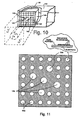
- a target in Fig. 11, includes a plurality of light-reflective, circular target elements or dots of light-colored or white retro-reflective material disposed in an array over a less reflective or dark-colored surface of a rigid substrate.
- Suitable retro-reflective materials include Nikkalite TM 1053 sold by Nippon Carbide Industries USA, Scotchlite TM 7610 sold by 3M Company, and D66-15xx TM sold by Reflexite, Inc.
- the target includes multiple circular dots so as to ensure that sufficient data input may be grabbed by the camera even in the case that several of the target elements have been smudged by handling or are otherwise not fully detectable.
- a well defined target includes approximately 30 circular dots very accurately positioned (within 0.0002") with respect to each other.
- the target illustrated in Fig. 11 might include 28 circular dots of 1" diameter very accurately positioned on a 2" x 2" grid, with four 11 ⁇ 4", dots and a single 11 ⁇ 2" diameter dot strategically positioned within the array.
- the target is typically manufactured using a photolithographic process to define the dot boundaries and ensure sharp-edge transition between light and dark areas, as well as accurate and repeatable positioning of the several target elements on the target face.
- the target face may also be covered with a glass or other protective layer. Note that since all information obtained from a particular target is unique to that target, the several targets used to align a vehicle need not be identical and can in fact be of different makeup and size. For example, it is convenient to use larger rear targets to compensate for the difference in distance to the camera.
- the system In order to accurately determine the position between the wheels on one side of the vehicle and the wheels on the other side of the vehicle, the system must know where one camera is positioned with respect to the other camera. This is accomplished during a calibration and set up operation wherein, as depicted in Fig. 9, a larger target 150 (presently 3' x 3') is positioned in the field of view of both cameras, typically along the centerline of the rack 111, and the approximately 30 feet away from the cameras. Information obtained from each camera is then used to determine the relative positions and orientations of the cameras. More specifically, since each camera will indicate where the target is with respect to itself, and since each is viewing the same target, the system can calculate where each camera is located and oriented with respect to the other. This is called a relative camera position (RCP) calibration.
- RCP relative camera position
- Such calibration allows the results obtained from one side of the vehicle to be compared to the other.
- the system can be used to locate the wheels on one side of the vehicle with respect to the other side from that point on.
- the RCP transfer function is used to convert one camera's coordinate system into the other camera's coordinate system so that a target viewed by one camera can be directly related to a target viewed by the other camera.
- the illustrated inspection process is monocular, meaning that by using one camera in one position, the position and orientation of a target with respect to the camera can be determined. This, of course, requires that the target be in view of the camera to accomplish the measurement. But since one camera can only conveniently view one side of the vehicle at a time without using reflectors as earlier described above, two spatially related cameras must be used to view both sides.
- the RCP transfer function then allows the information obtained by the two cameras to be coordinated and have the same effect as if all of the information had been obtained by a single camera.
- An advantage of the use of such a system is that, since each wheel is independently inspected and merely related back to the others, the system is independent of level and does not require leveling of the vehicle support rack or floor. Moreover, it is not necessary that the axles of all wheels be at the same height, i.e. , differences in tire sizes or inflation will not adversely affect measurement.
- a vehicle may be driven onto the rack 133, and, if desired, the vehicle lifted to an appropriate repair elevation.
- the target assemblies 126 are then attached to the wheel rims and manually oriented so that the target surfaces face the respective camera/light subsystems.
- the vehicle and model year are then entered into the keyboard 120 along with other relevant information which may include the vehicle VIN number, license number, owner name, etc.
- the system database includes specifications for each model that might be inspected, and upon identification of the particular vehicle under inspection extracts such information to assist in quickly locating the target images. Alternatively, previous inspection history can be used to indicate likely target location.
- the targets are highly accurate and their position and orientation relative to the rim of the wheel to which they are attached is known to an accuracy of 0.01" and 0.001°. If each wheel was perfect and the clamp was perfectly mounted one could argue that the wheel axle would be normal (90° in all directions) to the wheel plane determined by the rim edge. However, since wheels are normally not perfect and targets are not always perfectly mounted, such information would only indicate orientation and position of the wheel plane and not necessarily provide accurate information as to the orientation of the wheel axis. Such assumption is thus not made. However, by rolling the wheel from one position to another a new image can be taken, and from the position and orientation of the target in the two positions, the actual position and orientation of the wheel axis can be calculated.
- the vehicle can be mathematically modeled in three dimensions, and the alignment values in toe, camber, caster, thrust angle, etc. can be displayed with respect to the vehicle itself.
- the actual operator alignment procedure can proceed, and since the inspection is continuous, the results of each adjustment will be reflected on the system video screen.
- the operator can select various levels of assistance, including actual depictions of the location and parts to be adjusted to provide corrective action. Such information can even include the appropriate choice of tool to be used.
- each camera since each camera is referenced to the other, it is not necessary that the supporting rack be level or even that all wheels lie within the same plane.
- a reference plane must be identified. This can be accomplished by defining a reference plane that passes through the axles. But since one of the axles may not lie in the plane defined by the other three, some liberties must be taken. For example, for the purpose of aligning the front wheels, one might use the plane defined by the front axles and the average of the rear axles. A similar procedure might be used with respect to the rear wheels, etc. Wheel alignment would then be referenced to such a plane or planes. In addition, wheel position and thrust line measurements would also be referenced to such a plane or planes. Moreover, because of the independence of measurement, once a reference plane is defined, should one of the targets be blocked from view or become loose or even dislodged from a wheel, it will not necessarily affect measurements associated with other wheels.
- a single calibration target such as that illustrated at 150 in FIG. 9 may, however, in some respects be problematic.
- the orientation of the two cameras 122, 124 must be set up so that both cameras can see the same target; that is, the fields of view of the cameras must overlap at the position of the target 150. Since it is desirable that the cameras have as narrow a field of view as possible, e.g ., to optimize sensitivity and reduce optical distortion, the single target may have to be positioned a fairly substantial distance from the cameras so as to lie within the fields of view of both cameras. Therefore, it may be necessary to make the target large, unwieldy and expensive.
- a calibration target assembly such as that depicted at 160 in FIGS. 12a-12d.
- the illustrated assembly is comprised of a front target 162 and a rear target 164, respectively mounted in cantilevered fashion to opposite ends of a suitably configured rigid support structure formed by a two-piece telescoping beam 166, 167 mounted to upstanding support legs 168 and 169 rigidly affixed thereto.
- the beam parts 166 and 167 may be rigidly locked together at a desired extension by a suitable screw-clamp 165 or the like.
- the lower end of leg 168 is provided with a base 170 extending laterally to one side of the leg.
- Base 170 is provided with a supporting pad 171 disposed beneath its distal end.
- the lower end of leg 169 is provided with a base 172 that extends to both sides of leg 169 and has a support pad 173 disposed beneath one end thereof and a two position tilt mechanism 174 affixed to the other end.
- the tilt mechanism 174 is a simple repositionable support that in one position causes the base 172 to lie horizontal, and in a second position causes the entire assembly to be tilted slightly into a new orientation to allow the checking of a previously calculated calibration.
- targets 162 and 164 both extend laterally to the same side of beam 166, 167, the center of gravity of the structure is to one side of the beam 166, 167. Accordingly, the three supports 171, 173 and 174 are positioned in unbalanced relationship to the beam centerline so as to counter the unbalance caused by the side-mounted targets.
- targets 162 and 164 are for simplicity shown with plain faces, it will be understood that they are actually provided with optically detectable geometric designs of the type described above.
- the target faces are angularly disposed at typically 45° relative to the longitudinal axis of beam 166, 167 for reasons which will be discussed below.
- rear target 164 is somewhat larger than front target 162 to compensate for the difference in distance to the camera.
- beam part 167 Also affixed to beam part 167 are simple C-shaped handles 176 and 177 that may be used to lift the assembly to carry or move it from one position to another.
- the assembly In use, the assembly is normally extended as illustrated in FIG. 12a by the solid lines; however, as suggested by the dashed lines, by releasing the clamp 165, beam part 166 may be telescoped into beam part 167 to present a more compact assembly for transport or storage.
- both the front target 162 and rear target 164 will be within the field of view of camera 122. Neither target will necessarily lie within the field of view of the other camera 124. Since the targets 162 and 164 are now in positions similar to those of the left side targets previously disclosed with reference to FIG. 9, it will be appreciated that camera 122 can optically illuminate and detect the positions and orientations of the targets relative to its own position and optical axis, as well as to each other, by using the techniques described above.
- the system is not yet “calibrated” because the precise position and orientation of camera 124 relative to camera 122 is not yet known.
- the separation between targets 162 and 164 is now known and their angular relationship to each other is known, by simply lifting the assembly 160 and placing it in bridging relationship across the rack tracks 181 and 182 as illustrated in FIG. 14, so that target 164 now lies within the field of view of camera 122, and target 162 lies within the field of view of camera 124, the two cameras can respectively determine their position and orientation relative to the targets 164 and 162.
- the separation and relative orientation of the targets is both known and fixed, the system can accurately compute the orientation and position of camera 124 relative to camera 122.
- the technician can simply reposition or reorient the assembly 160 on rack 180 and cause the system to recompute the relative camera positions.
- One way to accomplish such reorientation is to simply extend or retract the tilt mechanism 174 into its other position; another is to move the assembly back a foot or so on the rack. If there is no change in camera position computation, the calibration may be considered accurately accomplished. This also insures that the assembly has remained rigid and dimensionally unchanged during its repositioning.
- the targets illustrated in FIGS. 12-14 are depicted as planar in configuration, it is to be understood that any other suitable target design could likewise be used so long as it includes features which enable the position and orientation of the target to be optically determined by the cameras 122, 124 or other optical inspection means.
- the targets need not necessarily be mounted to one side of the beam 160. For example, they could be mounted above or below the beam in any suitable manner that allows unobstructed viewing by the cameras when the assembly is disposed in the calibrating positions described above.
- one benefit of the disclosed structure is that the same targets, or type of targets, used in the subsequent wheel alignment operations can be affixed to the beam 160 in the same manner and using the same fastening techniques used to mount the targets to the auto wheels.
- "jounce" measurements i.e. , a measurement of suspension dynamics
- articles of manufacture one might wish to embody a target in the form of a label and affix the label to parts on an assembly line, and then use the apparatus to track the position and/or orientation of the article as it moves down the line.
- targets affixed to various moving parts could be used to accurately follow the motion of the arm as objects are carried thereby.
- system in accordance with the present invention to determine or maintain alignment of various points on the structure relative to other points.
- territorial space one might use the system to develop topological surveys of ground surface contours.
- this apparatus can also be used to determine the condition of the shock absorbers of the vehicle. This is done by firstly "jouncing" the vehicle. Jouncing a vehicle is a normal step in alignment procedures, or, for that matter, checking the shock absorbers, and entails applying a single vertical force to the vehicle by, eg. pushing down onto the hood of the vehicle and releasing the vehicle, to cause it to oscillate up and down. Secondly, as the vehicle oscillates up and down, the apparatus of the invention takes readings of the targets on each of the wheels. In so doing, the movement of the targets, which will define a dampened waveform, can be monitored to determine the extent of the dampening. If the dampening is not sufficient (i.e. the up and down movement or rocking of the vehicle does not stop soon enough) this indicates that the shock absorbers are faulty.
- This method is particularly advantageous in that a determination can be made as to the soundness of a specific shock absorber; a result which can be indicated to the operator of the alignment apparatus by means of the computer 32.
- any suitable portion of the body of the motor vehicle can be selected to monitor the oscillation of the vehicle. So, for example, the apparatus can focus on the edge of the wheel housing or, alternatively, a small target placed on a convenient position on the body work of the motor vehicle.
- this apparatus can be used to calculate the ride height of the motor vehicle.
- This parameter is particularly important in the determination of the alignment of the wheels of vehicles such as pick-ups which, in operation, may carry a load. This load would have the effect of lowering the vehicle and it is, therefore, preferable to make allowance for this during alignment procedures.
- the ride height, or height of the chassis of the vehicle from the floor is determined by physically measuring it with an instrument such as a tape measure. This measurement is then compared to standard tables which yield a compensation factor for the vehicle concerned.
- the described method and apparatus can, however, make this measurement directly by viewing an appropriate portion of the body and determining its height from the test bed on which the vehicle rests. Once this height has been determined it can be compared to standard look-up tables stored within the computer which can, in turn, produce the compensation factor.
- a general advantage of the above-described apparatus is that it is relatively simple to use as no delicate mechanical or electronic equipment need be attached to the wheels of the motor vehicle concerned.
- the sensitive and delicate equipment is mounted within a housing which stands independent and distant from the motor vehicle being tested, no damage can be caused to it if the motor vehicle were, for example, to be driven off the wheel guides.
- prior art heads can be knocked out of calibration by simple jarring or dropping, it takes major damage to the wheel-mounted components to affect the calculated results.
- Another advantage is that the equipment requires very few operator commands and could readily be made hands free with simple auditory outputs and equally simple voice recognition means to receive and/or record operator responses and/or commands.
- the described system has the further advantage that alignment determinations can be done relatively quickly. This allows a higher turn around rate within the business conducting the alignment determinations.
- a still further advantage of this apparatus is that it can be placed, as is illustrated in FIG. 4, above and out of the way of the motor vehicle being tested. This has the distinct advantage that the chances of damaging the sensitive alignment determining apparatus is substantially reduced as the apparatus is out of the way of the motor vehicle. Another advantage of this configuration is that the measuring apparatus uses minimal floor space and has no equipment blocking access to the front of the motor vehicle.
- this apparatus has the advantage that it is unnecessary to jack the vehicle up to make the required calculations for "run-out".
- this apparatus can be used to determine information other than the relative alignment of the wheels.
- the alignment apparatus if equipped with a suitable character recognition capability, could be used to read the license plate of the motor vehicle which could, in turn, yield information such as the make and model of the vehicle and its service history (if available) and, therefore, the required alignment parameters of such vehicle. This would save the operator from entering the motor vehicle's details into the apparatus.
- similar information can also be obtained by optically viewing and processing the bar-coded plate.
- it would also be possible to optically identify the vehicle type by comparing certain features of the body or trim thereof to database information.
- Yet another advantage of the system is that no wires, cords or beams of light pass in front of the vehicle being tested. As most alignment correction is made by accessing the wheels of the car from the front, wires, cords or beams passing in front of the vehicle tend to get in the way of the technician. Often these wires, cords or beams are sensitive to being interfered with and so their absence makes alignment correction work much easier.
- the targets are not interlinked or interdependent, after initial capture of target images, it is possible to block off one of the targets from the camera's view without interfering with the orientation calculations for the other wheels.
- all the test heads are interdependent and cannot function if one of the heads is "blocked" out.
- the apparatus could define a reference point for each wheel with the referent point being located at, say, the intersection of the axis of rotation of the wheel, with that wheel. These points can then be processed to define an approximately horizontal reference plane, relative to which the alignment of the wheels can be calculated.
- This method has the particular advantage that the rack on which the vehicle is being supported does not have to be levelled, a process which requires expensive apparatus and which is necessary to define a horizontal reference plane and which is used in prior art alignment devices.
Claims (9)
- Kombination eines optoelektronischen Ausrichtsystems sowie einer Vorrichtung zum Kalibrieren dieses optoelektronischen Ausrichtsystems, wobei die Kombination umfasst:wenigstens eine erste und zweite optische Inspektionseinrichtung (122,124), die im Abstand voneinander angeordnet sind;einen zugeordneten Datenprozessor (32), der zum Inspizieren und Bestimmen der Lage und Orientierung relativ zu den Inspektionseinrichtungen von Zielen geeignet ist, die an auszurichtenden Gegenständen, wie Fahrzeugrädern, befestigt sind, um aus dieser Bestimmung die Lage und Orientierung der Gegenstände zu erschließen, an denen die Ziele befestigt sind;ein erstes und zweites Ziel (164,162), deren jedes vorbestimmte geometrische Merkmale aufweist, die optisch erfasst werden können;einen langgestreckten Balken (166,167), der das erste und zweite Ziel (164,162) in starrer Anordnung relativ zueinander und in einem vorbestimmten festen Abstand voneinander trägt, so dass, wenn der langgestreckte Balken (166,167) relativ zu einer Arbeitsfläche derart angeordnet ist, dass sowohl das erste als auch das zweite Ziel (164,162) innerhalb des Betrachtungsfeldes der ersten Inspektionseinrichtung liegt, das Ausrichtsystem so angeordnet und ausgebildet ist, dass es die Ziele (164,162) optisch inspiziert, um eine erste optische Information zu erhalten, die für die Bestimmung der Lage und Orientierung jedes der Ziele (164,162) relativ zu der ersten Inspektionseinrichtung (122) brauchbar ist, und, wenn der langgestreckte Balken (166,167) derart umorientiert wird, dass das erste Ziel (164) innerhalb des Blickfeldes der ersten Inspektionseinrichtung (122) liegt und das zweite Ziel (162) innerhalb des Blickfeldes der zweiten Inspektionseinrichtung (124)liegt, das Ausrichtsystem so ausgebildet und angeordnet ist, dass es die Ziele (164,162) optisch inspiziert, um eine zweite optische Information zu erhalten, die zur Bestimmung der gegenwärtigen Lage und Orientierung des ersten Zieles (164) relativ zu der ersten Inspektionseinrichtung (122) und der gegenwärtigen Lage und Orientierung des zweiten Zieles (162) relativ zu der zweiten Inspektionseinrichtung (124) brauchbar ist, wobei das Ausrichtsystem so ausgebildet und angeordnet ist, dass es die erste und zweite optische Information benutzt, um die genaue Lage und Orientierung der zweiten Inspektionseinrichtung (124) relativ zu der ersten Inspektionseinrichtung (122) zu berechnen.
- Kombination nach Anspruch 1, bei welcher die Ziele (164,162) Flächen aufweisen, die eben sind und unter vorbestimmten Winkeln bezüglich der Länge des Balkens (166,167) orientiert sind.
- Kombination nach Anspruch 2, bei welcher jede Zielfläche unter einem Winkel von 45° relativ zur Länge des Balkens (166,167) orientiert ist.
- Kombination nach Anspruch 1, bei welcher Stützeinrichtungen (168,169) zum Stützen des Balkens (166,167) in einer vorbestimmten Höhe oberhalb einer Arbeitsfläche vorgesehen sind, wobei die Stützeinrichtungen (168,169) ein Paar von vertikal ausgerichteten Stützbeinen aufweist, deren eines Ende am Balken (166,167) starr befestigt sind und deren entgegengesetzte Enden an einer Basis (170,172) befestigt sind, die zum Stützen des Balkens (166,167) und der daran befestigten Zieleinrichtungen (164,162) geeignet ist.
- Kombination nach Anspruch 1, bei welcher die erste und zweite Zieleinrichtung (164,162) beide auf einer Seite des Balkens (166,167) angeordnet sind.
- Kombination nach Anspruch 1, bei welcher der Balken (166,167) ein zweiteiliger Mechanismus ist, wobei ein Teil teleskopartig innerhalb des anderen aufgenommen ist, so dass er zur Lagerung teleskopartig zusammenschiebbar und zum Kalibrieren teleskopartig ausfahrbar ist.
- Verfahren zum Kalibrieren eines optoelektronischen Ausrichtsystems mit einer ersten und zweiten optischen Inspektionseinrichtung (122,124),die im Abstand voneinander angeordnet sind, und einem zugehörigen Datenprozessor (117), das zum Inspizieren und Bestimmen der Lage und Orientierung relativ zu den Inspektionseinrichtungen von Zielen (54) geeignet ist, die an auszurichtenden Gegenständen, wie Fahrzeugrädern (22L,22R,24L,24R) befestigt sind, um aus dieser Bestimmung die Lage und Orientierung der Objekte (22L,22R,24L,24R) zu erschließen, an denen die Ziele (54) befestigt sind, wobei das Verfahren die folgenden Schritte umfasst:Vorsehen einer ersten und zweiten Zieleinrichtung (164,162);Vorsehen einer Einrichtung (168,169) zum Stützen der ersten und zweiten Zieleinrichtung (164,162) in starrer Anordnung relativ zueinander und in vorbestimmtem festem Abstand voneinander;Anordnen der Stützeinrichtung (168,169) relativ zu einer Arbeitsfläche derart, dass sowohl die erste als auch die zweite Zieleinrichtung (164,162) innerhalb des Blickfeldes der ersten Inspektionseinrichtung (122) liegen;optisches Inspizieren der ersten und zweiten Zieleinrichtung (168,169), um eine erste optische Information zur Bestimmung der Lage und Orientierung jeder der Zieleinrichtungen (168,169) relativ zu der ersten Inspektionseinrichtung (122) zu erhalten;Umorientieren der Stützeinrichtung (168,169) derart, dass die erste Zieleinrichtung (164) innerhalb des Blickfeldes der ersten Inspektionseinrichtung (122) liegt und die zweite Zieleinrichtung (162) innerhalb des Blickfeldes der zweiten Inspektionseinrichtung (124)liegt, und abermals optisches Inspizieren der ersten und zweiten Zieleinrichtung (164,162), um eine zweite optische Information zu erhalten, die zur Bestimmung der gegenwärtigen Lage und Orientierung der ersten Zieleinrichtung (164) relativ zu der ersten Inspektionseinrichtung (122) und der gegenwärtigen Lage und Orientierung der zweiten Zieleinrichtung (162) relativ zur zweiten Inspektionseinrichtung (124) brauchbar ist; undVerwenden der ersten und zweiten optischen Information, um die genaue Lage und Orientierung der zweiten Inspektionseinrichtung (124) relativ zur ersten Inspektionseinrichtung (122) zu berechnen.
- Verfahren nach Anspruch 7, bei welchem die erste und zweite Zieleinrichtung (164,162) Zielflächen aufweisen, die allgemein eben sind und vorbestimmte Winkelorientierung relativ zur Stützeinrichtung (168,169) aufweisen.
- Verfahren nach Anspruch 8, bei welchem jede Zielfläche unter 45° bezüglich einer imaginären Linie orientiert ist, welche die erste und zweite Zieleinrichtung (164,162) verbindet.
Applications Claiming Priority (3)
| Application Number | Priority Date | Filing Date | Title |
|---|---|---|---|
| US716585 | 1996-09-18 | ||
| US08/716,585 US5809658A (en) | 1993-09-29 | 1996-09-18 | Method and apparatus for calibrating cameras used in the alignment of motor vehicle wheels |
| PCT/US1997/016381 WO1998012503A1 (en) | 1996-09-18 | 1997-09-11 | Calibrating cameras used in alignment of wheels |
Publications (3)
| Publication Number | Publication Date |
|---|---|
| EP0927335A1 EP0927335A1 (de) | 1999-07-07 |
| EP0927335A4 EP0927335A4 (de) | 2000-11-22 |
| EP0927335B1 true EP0927335B1 (de) | 2003-04-16 |
Family
ID=24878611
Family Applications (1)
| Application Number | Title | Priority Date | Filing Date |
|---|---|---|---|
| EP97942498A Expired - Lifetime EP0927335B1 (de) | 1996-09-18 | 1997-09-11 | Kalibrierung von kameras bei anwendung in radjustierung |
Country Status (9)
| Country | Link |
|---|---|
| US (1) | US5809658A (de) |
| EP (1) | EP0927335B1 (de) |
| JP (1) | JP3454433B2 (de) |
| KR (1) | KR100367124B1 (de) |
| AU (1) | AU713446B2 (de) |
| BR (1) | BR9711500A (de) |
| CA (1) | CA2266071A1 (de) |
| DE (2) | DE927335T1 (de) |
| WO (1) | WO1998012503A1 (de) |
Cited By (2)
| Publication number | Priority date | Publication date | Assignee | Title |
|---|---|---|---|---|
| DE102006041822A1 (de) * | 2006-09-06 | 2008-03-27 | Beissbarth Gmbh | Verfahren zur Fahrwerksmessung eines Kraftfahrzeugs, Fahrwerksvermessungseinrichtung sowie Kraftfahrzeugprüfstrasse |
| CN102883988A (zh) * | 2010-02-12 | 2013-01-16 | 实耐宝公司 | 用于将车辆引导至服务升降机上的装置 |
Families Citing this family (88)
| Publication number | Priority date | Publication date | Assignee | Title |
|---|---|---|---|---|
| US5724743A (en) * | 1992-09-04 | 1998-03-10 | Snap-On Technologies, Inc. | Method and apparatus for determining the alignment of motor vehicle wheels |
| US6259827B1 (en) | 1996-03-21 | 2001-07-10 | Cognex Corporation | Machine vision methods for enhancing the contrast between an object and its background using multiple on-axis images |
| US6075881A (en) | 1997-03-18 | 2000-06-13 | Cognex Corporation | Machine vision methods for identifying collinear sets of points from an image |
| US6405111B2 (en) * | 1997-05-16 | 2002-06-11 | Snap-On Technologies, Inc. | System and method for distributed computer automotive service equipment |
| US6608647B1 (en) | 1997-06-24 | 2003-08-19 | Cognex Corporation | Methods and apparatus for charge coupled device image acquisition with independent integration and readout |
| US5978521A (en) * | 1997-09-25 | 1999-11-02 | Cognex Corporation | Machine vision methods using feedback to determine calibration locations of multiple cameras that image a common object |
| US6381375B1 (en) | 1998-02-20 | 2002-04-30 | Cognex Corporation | Methods and apparatus for generating a projection of an image |
| US6381366B1 (en) | 1998-12-18 | 2002-04-30 | Cognex Corporation | Machine vision methods and system for boundary point-based comparison of patterns and images |
| US6687402B1 (en) | 1998-12-18 | 2004-02-03 | Cognex Corporation | Machine vision methods and systems for boundary feature comparison of patterns and images |
| US7982725B2 (en) * | 1999-05-25 | 2011-07-19 | Silverbrook Research Pty Ltd | Sensing device with inductive charging |
| DE19934864A1 (de) * | 1999-07-24 | 2001-02-08 | Bosch Gmbh Robert | Vorrichtung zum Bestimmen der Rad- und/oder Achsgeometrie von Kraftfahrzeugen |
| JP3827480B2 (ja) * | 1999-08-13 | 2006-09-27 | 日立建機株式会社 | 自動運転建設機械およびその位置計測手段の校正方法 |
| US6237234B1 (en) | 1999-09-28 | 2001-05-29 | Snap-On Technologies, Inc. | Method and apparatus for measuring vehicle wheel roll radius |
| US6684402B1 (en) | 1999-12-01 | 2004-01-27 | Cognex Technology And Investment Corporation | Control methods and apparatus for coupling multiple image acquisition devices to a digital data processor |
| US6323776B1 (en) | 1999-12-21 | 2001-11-27 | Snap-On Technologies, Inc. | Method and apparatus of automatically identifying faults in a machine vision measuring system |
| US6498959B1 (en) | 2000-01-19 | 2002-12-24 | Hunter Engineering Company | Apparatus and method for controlling a mechanism for positioning video cameras for use in measuring vehicle wheel alignment |
| AU2001245834A1 (en) * | 2000-03-23 | 2001-10-03 | Snap-On Technologies, Inc. | Self-calibrating, multi-camera machine vision measuring system |
| US6748104B1 (en) | 2000-03-24 | 2004-06-08 | Cognex Corporation | Methods and apparatus for machine vision inspection using single and multiple templates or patterns |
| US6560883B2 (en) * | 2000-06-28 | 2003-05-13 | Snap-On Technologies, Inc. | Method and system for conducting wheel alignment |
| EP1309832B1 (de) | 2000-08-14 | 2008-10-22 | Snap-on Incorporated | Selbstkalibrierendes 3D Messystem zur Ausrichtung von Kraftfahrzeugrädern |
| US6556971B1 (en) * | 2000-09-01 | 2003-04-29 | Snap-On Technologies, Inc. | Computer-implemented speech recognition system training |
| US6965324B1 (en) * | 2000-10-21 | 2005-11-15 | Robert W. Suggs, Sr. | Automotive picture and data acquisition center and method |
| US6594007B2 (en) | 2001-02-01 | 2003-07-15 | Snap-On Technologies, Inc. | Method and apparatus for mapping system calibration |
| US6839972B2 (en) * | 2001-06-15 | 2005-01-11 | Snap-On Incorporated | Self-calibrating position determination system |
| US6661505B2 (en) | 2001-06-28 | 2003-12-09 | Snap-On Technologies, Inc. | Method and system for measuring caster trail |
| US7062861B2 (en) * | 2001-06-28 | 2006-06-20 | Snap-On Incorporated | Self-calibrating position determination system and user interface |
| JP2005517896A (ja) * | 2001-06-28 | 2005-06-16 | スナップ − オン テクノロジーズ,インコーポレイテッド | 自動較正位置決定システム |
| US20030035138A1 (en) * | 2001-08-17 | 2003-02-20 | Schilling Mary K. | Internet-based custom package-printing process |
| US7302093B2 (en) * | 2002-03-26 | 2007-11-27 | Hunter Engineering Company | Color vision vehicle wheel alignment system |
| DE10229336A1 (de) * | 2002-06-29 | 2004-01-15 | Robert Bosch Gmbh | Verfahren und Vorrichtung zur Kalibrierung von Bildsensorsystemen |
| US7209161B2 (en) * | 2002-07-15 | 2007-04-24 | The Boeing Company | Method and apparatus for aligning a pair of digital cameras forming a three dimensional image to compensate for a physical misalignment of cameras |
| AU2003254228A1 (en) * | 2002-07-25 | 2004-04-19 | Snap-On Technologies, Inc. | Diagnosing malfunctioning wheel alignment system |
| US6728609B2 (en) | 2002-09-16 | 2004-04-27 | Snap-On Technologies, Inc. | Diagnostic method and system for a multiple-link steering system |
| US6823601B2 (en) * | 2002-09-17 | 2004-11-30 | Snap-On Incorporated | Apparatus for use with a 3D image wheel aligner for facilitating adjustment of an adaptive cruise control sensor on a motor vehicle |
| US20040172170A1 (en) * | 2002-12-02 | 2004-09-02 | Lesert Brooks R. | Portable wheel alignment device |
| US6871409B2 (en) * | 2002-12-18 | 2005-03-29 | Snap-On Incorporated | Gradient calculating camera board |
| DE10259954A1 (de) * | 2002-12-20 | 2004-07-01 | Robert Bosch Gmbh | Vorrichtung zur Bestimmung der Rad- und/oder Achsgeometrie von Kraftfahrzeugen |
| CN1742193B (zh) * | 2003-01-27 | 2010-04-28 | 斯耐普昂技术有限公司 | 车轮定位设备的校准检定 |
| US7121011B2 (en) * | 2003-05-09 | 2006-10-17 | Snap-On Incorporated | Camera technique for adaptive cruise control (ACC) sensor adjustment |
| EP1649246A1 (de) * | 2003-07-31 | 2006-04-26 | Snap-on Incorporated | Ausrichtungs-justiermethode für zwei räder |
| US7415324B2 (en) * | 2003-07-31 | 2008-08-19 | Snap-On Incorporated | Vehicle wheel alignment adjustment method |
| US20050038580A1 (en) * | 2003-08-15 | 2005-02-17 | Seim Kerri Jean | Information about structural integrity of vehicles |
| US20050060899A1 (en) * | 2003-09-23 | 2005-03-24 | Snap-On Technologies, Inc. | Invisible target illuminators for 3D camera-based alignment systems |
| US7164472B2 (en) * | 2003-10-09 | 2007-01-16 | Hunter Engineering Company | Common reference target machine vision wheel alignment system |
| WO2006074026A1 (en) * | 2004-12-30 | 2006-07-13 | Snap-On Incorporated | Non-contact vehicle measurement method and system |
| ITRE20050043A1 (it) * | 2005-04-26 | 2006-10-27 | Corghi Spa | Metodo e dispositivo per determinare l'assetto delle ruote di un veicolo |
| CN101175971B (zh) * | 2005-05-13 | 2010-06-16 | 斯耐普昂公司 | 车轮校准器测量模块附连系统 |
| US20070040065A1 (en) * | 2005-08-19 | 2007-02-22 | Von Thal German | Flexible refueling boom extendable tube |
| US7444752B2 (en) | 2005-09-28 | 2008-11-04 | Hunter Engineering Company | Method and apparatus for vehicle service system optical target |
| US8111904B2 (en) | 2005-10-07 | 2012-02-07 | Cognex Technology And Investment Corp. | Methods and apparatus for practical 3D vision system |
| US8162584B2 (en) | 2006-08-23 | 2012-04-24 | Cognex Corporation | Method and apparatus for semiconductor wafer alignment |
| DE102006058383A1 (de) * | 2006-12-08 | 2008-06-12 | Robert Bosch Gmbh | Verfahren zur optischen Fahrwerksvermessung |
| US8132759B2 (en) * | 2007-03-21 | 2012-03-13 | The Boeing Company | System and method for facilitating aerial refueling |
| US7959110B2 (en) * | 2007-04-11 | 2011-06-14 | The Boeing Company | Methods and apparatus for resisting torsional loads in aerial refueling booms |
| US7424387B1 (en) | 2007-04-18 | 2008-09-09 | Snap-On Incorporated | Method for use with an optical aligner system for positioning a fixture relative to a vehicle |
| EP2153168B1 (de) | 2007-05-21 | 2017-05-10 | Snap-on Incorporated | Verfahren und vorrichtung zur radausrichtung |
| US7953247B2 (en) * | 2007-05-21 | 2011-05-31 | Snap-On Incorporated | Method and apparatus for wheel alignment |
| US7870677B2 (en) * | 2007-05-31 | 2011-01-18 | Snap-On Incorporated | Lightweight wheel clamp for vehicle wheel alignment system |
| US7640673B2 (en) * | 2007-08-01 | 2010-01-05 | Snap-On Incorporated | Calibration and operation of wheel alignment systems |
| US7855783B2 (en) * | 2007-09-18 | 2010-12-21 | Snap-On Incorporated | Integrated circuit image sensor for wheel alignment systems |
| DE102008042024A1 (de) * | 2008-09-12 | 2010-03-18 | Robert Bosch Gmbh | Verfahren und Vorrichtung zur optischen Achsvermessung von Kraftfahrzeugen |
| CN101726420B (zh) * | 2009-11-15 | 2011-09-07 | 吉林大学 | 三自由度车轮定位仪靶标 |
| US8104185B2 (en) * | 2009-12-18 | 2012-01-31 | Snap-On Incorporated | Lightweight wheel clamp for vehicle wheel alignment system |
| IT1399988B1 (it) * | 2010-05-05 | 2013-05-09 | Space S R L Con Unico Socio | Sistema, e relativo metodo, di determinazione dell'allineamento delle ruote di un veicolo |
| DE102010040637A1 (de) * | 2010-09-13 | 2012-03-15 | Robert Bosch Gmbh | Verfahren zum Kalibrieren eines Messwertaufnehmers |
| IT1404235B1 (it) * | 2010-12-30 | 2013-11-15 | Space S R L Con Unico Socio | Dispositivo di rilevamento, e relativo sistema di determinazione dell'orientamento delle ruote di un veicolo |
| CN102589903A (zh) * | 2011-12-22 | 2012-07-18 | 上海一成汽车检测设备科技有限公司 | 汽车3d四轮定位仪晨检装置及其方法 |
| US9644952B2 (en) * | 2012-10-18 | 2017-05-09 | Hunter Engineering Company | Method for evaluating component calibration in machine vision vehicle wheel alignment system |
| KR101461423B1 (ko) | 2013-04-17 | 2014-11-20 | 장철환 | 타이어 얼라인먼트 검출장치 |
| KR101510336B1 (ko) * | 2013-11-14 | 2015-04-07 | 현대자동차 주식회사 | 차량용 운전자 지원 시스템의 검사 장치 |
| KR101510338B1 (ko) * | 2013-11-22 | 2015-04-07 | 현대자동차 주식회사 | 차량용 차선 이탈 경보 시스템의 검사 장치 |
| DE102014204691A1 (de) * | 2014-03-13 | 2015-09-17 | Robert Bosch Gmbh | Bildaufnahmevorrichtung, insbesondere zur Fahrzeugvermessung |
| EP3234502A4 (de) | 2014-12-17 | 2018-08-15 | Snap-On Incorporated | Live-messung der bodenfreiheit |
| CN107208997B (zh) | 2015-01-07 | 2020-06-05 | 实耐宝公司 | 滚动中的虚拟轮轴校准 |
| CN105823471B (zh) * | 2015-01-28 | 2020-03-17 | 株式会社拓普康 | 三维位置计测系统 |
| DE102015209246A1 (de) * | 2015-05-20 | 2016-11-24 | Robert Bosch Gmbh | System und Verfahren zur Durchführung von Einstellarbeiten an einem Kraftfahrzeug |
| KR101541013B1 (ko) | 2015-06-03 | 2015-08-04 | 삼홍엔지니어링 주식회사 | 휠 얼라인먼트 캘리브레이션 방법, 및 이에 적용되는 각도 및 길이 조절이 가능한 캘리브레이션 바 |
| JP6484515B2 (ja) * | 2015-07-09 | 2019-03-13 | 株式会社日立製作所 | 油入機器の漏油検出装置 |
| JP6658054B2 (ja) * | 2016-02-16 | 2020-03-04 | トヨタ車体株式会社 | 車体部品の施工部位判定システム及び施工部位判定方法 |
| JP6500852B2 (ja) * | 2016-07-11 | 2019-04-17 | 株式会社安川電機 | ロボットシステム、ロボットの制御方法、ロボットコントローラ |
| DE112017004974T5 (de) * | 2016-09-30 | 2019-06-19 | Burke E. Porter Machinery Company | Radeinstellungsmessverfahren und System für Fahrzeugräder |
| CN108453646A (zh) * | 2018-04-20 | 2018-08-28 | 深圳市道通科技股份有限公司 | 装夹装置及汽车标定设备 |
| CN109059769B (zh) * | 2018-08-31 | 2020-08-28 | 中国科学院力学研究所 | 一种非接触式受电弓升降弓臂杆位置关系测量方法 |
| CN210106906U (zh) * | 2019-02-01 | 2020-02-21 | 深圳市道通合创软件开发有限公司 | 一种标定系统及其标定支架 |
| IT201900022944A1 (it) | 2019-12-04 | 2021-06-04 | Nexion Spa | Apparato e metodo per la rilevazione dell’assetto di un veicolo |
| JP7284118B2 (ja) * | 2020-03-11 | 2023-05-30 | 本田技研工業株式会社 | ターゲット設置装置 |
| JP2022111730A (ja) * | 2021-01-20 | 2022-08-01 | 本田技研工業株式会社 | ターゲット設置装置及びそれを用いたターゲット設置方法 |
| CN114878145B (zh) * | 2022-05-05 | 2023-01-03 | 中国科学院长春光学精密机械与物理研究所 | 一种基于温度畸变值评价光学传函影响的方法和系统 |
Family Cites Families (9)
| Publication number | Priority date | Publication date | Assignee | Title |
|---|---|---|---|---|
| US2292969A (en) * | 1939-12-20 | 1942-08-11 | Albert P Peters | Aligning device |
| US3288020A (en) * | 1963-01-08 | 1966-11-29 | Fmc Corp | Apparatus for optically measuring wheel alignment characteristics |
| US3501240A (en) * | 1966-09-09 | 1970-03-17 | Fmc Corp | Optical wheel alignment apparatus |
| DE2948573A1 (de) * | 1979-12-03 | 1981-06-04 | Siemens AG, 1000 Berlin und 8000 München | Verfahren und anordnung zur beruehrungslosen achsvermessung an kraftfahrzeugen |
| US4588194A (en) * | 1985-02-04 | 1986-05-13 | Steidle Daniel L | Target device with remote resetting means |
| US4726122A (en) * | 1986-11-03 | 1988-02-23 | Nicator Ab | Wheel alignment apparatus for vehicles |
| US5274433A (en) * | 1989-07-07 | 1993-12-28 | Miradco | Laser-based wheel alignment system |
| EP0674759B1 (de) * | 1992-09-04 | 2001-07-18 | Snap-on Technologies, Inc. | Verfahren und vorrichtung zur bestimmung der ausrichtung von kraftfahrzeugrädern |
| US5342062A (en) * | 1992-12-17 | 1994-08-30 | Lance Land & Livestock Ltd. | Gallery, silhouette, and target system which is easily resettable, collapsible, and portable |
-
1996
- 1996-09-18 US US08/716,585 patent/US5809658A/en not_active Expired - Lifetime
-
1997
- 1997-09-11 EP EP97942498A patent/EP0927335B1/de not_active Expired - Lifetime
- 1997-09-11 WO PCT/US1997/016381 patent/WO1998012503A1/en active IP Right Grant
- 1997-09-11 DE DE0927335T patent/DE927335T1/de active Pending
- 1997-09-11 BR BR9711500-2A patent/BR9711500A/pt not_active Application Discontinuation
- 1997-09-11 CA CA002266071A patent/CA2266071A1/en not_active Abandoned
- 1997-09-11 DE DE69721022T patent/DE69721022T2/de not_active Expired - Lifetime
- 1997-09-11 KR KR10-1999-7002282A patent/KR100367124B1/ko not_active IP Right Cessation
- 1997-09-11 JP JP51481398A patent/JP3454433B2/ja not_active Expired - Lifetime
- 1997-09-11 AU AU44184/97A patent/AU713446B2/en not_active Expired
Cited By (3)
| Publication number | Priority date | Publication date | Assignee | Title |
|---|---|---|---|---|
| DE102006041822A1 (de) * | 2006-09-06 | 2008-03-27 | Beissbarth Gmbh | Verfahren zur Fahrwerksmessung eines Kraftfahrzeugs, Fahrwerksvermessungseinrichtung sowie Kraftfahrzeugprüfstrasse |
| CN102883988A (zh) * | 2010-02-12 | 2013-01-16 | 实耐宝公司 | 用于将车辆引导至服务升降机上的装置 |
| US9452917B2 (en) | 2010-02-12 | 2016-09-27 | Snap-On Incorporated | Apparatus for guiding a vehicle onto a service lift using a machine vision wheel alignment system |
Also Published As
| Publication number | Publication date |
|---|---|
| AU713446B2 (en) | 1999-12-02 |
| BR9711500A (pt) | 2001-11-20 |
| AU4418497A (en) | 1998-04-14 |
| US5809658A (en) | 1998-09-22 |
| EP0927335A4 (de) | 2000-11-22 |
| CA2266071A1 (en) | 1998-03-26 |
| EP0927335A1 (de) | 1999-07-07 |
| WO1998012503A1 (en) | 1998-03-26 |
| DE927335T1 (de) | 1999-12-09 |
| KR100367124B1 (ko) | 2003-01-06 |
| DE69721022D1 (de) | 2003-05-22 |
| JP2001501730A (ja) | 2001-02-06 |
| JP3454433B2 (ja) | 2003-10-06 |
| KR20000036220A (ko) | 2000-06-26 |
| DE69721022T2 (de) | 2004-04-01 |
Similar Documents
| Publication | Publication Date | Title |
|---|---|---|
| EP0927335B1 (de) | Kalibrierung von kameras bei anwendung in radjustierung | |
| US5943783A (en) | Method and apparatus for determining the alignment of motor vehicle wheels | |
| EP0674759B1 (de) | Verfahren und vorrichtung zur bestimmung der ausrichtung von kraftfahrzeugrädern | |
| US6532062B2 (en) | Method and apparatus for measuring vehicle wheel scrub radius | |
| US6894771B1 (en) | Wheel alignment apparatus and method utilizing three-dimensional imaging | |
| US7424387B1 (en) | Method for use with an optical aligner system for positioning a fixture relative to a vehicle | |
| US7369222B2 (en) | Wheel aligner measurement module attachment system | |
| US8638452B2 (en) | Measuring head for a chassis measuring system, chassis measuring system and method for determining the position parameters of measuring heads of a chassis measuring system | |
| US6526665B2 (en) | Glint-resistant position determination system | |
| US20050068522A1 (en) | Wheel alignment apparatus and method utilizing three-dimensional imaging | |
| CA2383989A1 (en) | Method and apparatus for measuring vehicle wheel roll radius | |
| AU669211C (en) | Method and apparatus for determining the alignment of motor vehicle wheels |
Legal Events
| Date | Code | Title | Description |
|---|---|---|---|
| PUAI | Public reference made under article 153(3) epc to a published international application that has entered the european phase |
Free format text: ORIGINAL CODE: 0009012 |
|
| 17P | Request for examination filed |
Effective date: 19990301 |
|
| AK | Designated contracting states |
Kind code of ref document: A1 Designated state(s): DE FR GB IT NL |
|
| ITCL | It: translation for ep claims filed |
Representative=s name: BOTTI &FERRARI S.R.L. |
|
| EL | Fr: translation of claims filed | ||
| DET | De: translation of patent claims | ||
| A4 | Supplementary search report drawn up and despatched |
Effective date: 20001006 |
|
| AK | Designated contracting states |
Kind code of ref document: A4 Designated state(s): DE FR GB IT NL |
|
| 17Q | First examination report despatched |
Effective date: 20010914 |
|
| GRAH | Despatch of communication of intention to grant a patent |
Free format text: ORIGINAL CODE: EPIDOS IGRA |
|
| GRAH | Despatch of communication of intention to grant a patent |
Free format text: ORIGINAL CODE: EPIDOS IGRA |
|
| GRAA | (expected) grant |
Free format text: ORIGINAL CODE: 0009210 |
|
| AK | Designated contracting states |
Designated state(s): DE FR GB IT NL |
|
| PG25 | Lapsed in a contracting state [announced via postgrant information from national office to epo] |
Ref country code: NL Free format text: LAPSE BECAUSE OF FAILURE TO SUBMIT A TRANSLATION OF THE DESCRIPTION OR TO PAY THE FEE WITHIN THE PRESCRIBED TIME-LIMIT Effective date: 20030416 |
|
| REG | Reference to a national code |
Ref country code: GB Ref legal event code: FG4D |
|
| REF | Corresponds to: |
Ref document number: 69721022 Country of ref document: DE Date of ref document: 20030522 Kind code of ref document: P |
|
| NLV1 | Nl: lapsed or annulled due to failure to fulfill the requirements of art. 29p and 29m of the patents act | ||
| ET | Fr: translation filed | ||
| PLBE | No opposition filed within time limit |
Free format text: ORIGINAL CODE: 0009261 |
|
| STAA | Information on the status of an ep patent application or granted ep patent |
Free format text: STATUS: NO OPPOSITION FILED WITHIN TIME LIMIT |
|
| 26N | No opposition filed |
Effective date: 20040119 |
|
| REG | Reference to a national code |
Ref country code: FR Ref legal event code: PLFP Year of fee payment: 20 |
|
| PGFP | Annual fee paid to national office [announced via postgrant information from national office to epo] |
Ref country code: GB Payment date: 20160927 Year of fee payment: 20 |
|
| PGFP | Annual fee paid to national office [announced via postgrant information from national office to epo] |
Ref country code: FR Payment date: 20160926 Year of fee payment: 20 |
|
| PGFP | Annual fee paid to national office [announced via postgrant information from national office to epo] |
Ref country code: DE Payment date: 20160928 Year of fee payment: 20 |
|
| PGFP | Annual fee paid to national office [announced via postgrant information from national office to epo] |
Ref country code: IT Payment date: 20160923 Year of fee payment: 20 |
|
| REG | Reference to a national code |
Ref country code: DE Ref legal event code: R071 Ref document number: 69721022 Country of ref document: DE |
|
| REG | Reference to a national code |
Ref country code: GB Ref legal event code: PE20 Expiry date: 20170910 |
|
| PG25 | Lapsed in a contracting state [announced via postgrant information from national office to epo] |
Ref country code: GB Free format text: LAPSE BECAUSE OF EXPIRATION OF PROTECTION Effective date: 20170910 |