EP0925855A2 - Dispositif pour le refroidissement contrÔlé de profilés laminés à chaud, en particulier de poutres, directement à partir de la température de laminage - Google Patents
Dispositif pour le refroidissement contrÔlé de profilés laminés à chaud, en particulier de poutres, directement à partir de la température de laminage Download PDFInfo
- Publication number
- EP0925855A2 EP0925855A2 EP98124114A EP98124114A EP0925855A2 EP 0925855 A2 EP0925855 A2 EP 0925855A2 EP 98124114 A EP98124114 A EP 98124114A EP 98124114 A EP98124114 A EP 98124114A EP 0925855 A2 EP0925855 A2 EP 0925855A2
- Authority
- EP
- European Patent Office
- Prior art keywords
- cooling
- nozzles
- profile
- profiles
- nozzle
- Prior art date
- Legal status (The legal status is an assumption and is not a legal conclusion. Google has not performed a legal analysis and makes no representation as to the accuracy of the status listed.)
- Withdrawn
Links
- 238000001816 cooling Methods 0.000 title claims abstract description 83
- 238000005096 rolling process Methods 0.000 title claims description 10
- 239000007921 spray Substances 0.000 claims abstract description 19
- 239000002826 coolant Substances 0.000 claims abstract description 12
- 229910000831 Steel Inorganic materials 0.000 claims description 8
- 239000010959 steel Substances 0.000 claims description 8
- XLYOFNOQVPJJNP-UHFFFAOYSA-N water Substances O XLYOFNOQVPJJNP-UHFFFAOYSA-N 0.000 claims description 4
- 238000005507 spraying Methods 0.000 claims description 3
- 230000007704 transition Effects 0.000 claims description 3
- 239000002131 composite material Substances 0.000 claims description 2
- 239000000443 aerosol Substances 0.000 claims 1
- 239000012809 cooling fluid Substances 0.000 claims 1
- 238000003491 array Methods 0.000 abstract 1
- 238000009434 installation Methods 0.000 abstract 1
- 238000000034 method Methods 0.000 description 12
- 230000008569 process Effects 0.000 description 10
- 229910000734 martensite Inorganic materials 0.000 description 9
- 230000000694 effects Effects 0.000 description 8
- 239000000463 material Substances 0.000 description 6
- 239000000969 carrier Substances 0.000 description 4
- 238000009826 distribution Methods 0.000 description 4
- 230000000712 assembly Effects 0.000 description 3
- 238000000429 assembly Methods 0.000 description 3
- 230000008859 change Effects 0.000 description 3
- 238000005496 tempering Methods 0.000 description 3
- 238000010438 heat treatment Methods 0.000 description 2
- 230000009466 transformation Effects 0.000 description 2
- 230000006978 adaptation Effects 0.000 description 1
- 238000005275 alloying Methods 0.000 description 1
- 238000004380 ashing Methods 0.000 description 1
- 230000015572 biosynthetic process Effects 0.000 description 1
- 239000000498 cooling water Substances 0.000 description 1
- 238000000265 homogenisation Methods 0.000 description 1
- 238000005098 hot rolling Methods 0.000 description 1
- 230000006872 improvement Effects 0.000 description 1
- 229910001562 pearlite Inorganic materials 0.000 description 1
- 230000035515 penetration Effects 0.000 description 1
- 230000002093 peripheral effect Effects 0.000 description 1
- 238000010791 quenching Methods 0.000 description 1
- 230000000171 quenching effect Effects 0.000 description 1
- 230000009467 reduction Effects 0.000 description 1
- 230000000630 rising effect Effects 0.000 description 1
- 230000000930 thermomechanical effect Effects 0.000 description 1
- 238000011282 treatment Methods 0.000 description 1
- 229910000859 α-Fe Inorganic materials 0.000 description 1
Images


Classifications
-
- B—PERFORMING OPERATIONS; TRANSPORTING
- B21—MECHANICAL METAL-WORKING WITHOUT ESSENTIALLY REMOVING MATERIAL; PUNCHING METAL
- B21B—ROLLING OF METAL
- B21B45/00—Devices for surface or other treatment of work, specially combined with or arranged in, or specially adapted for use in connection with, metal-rolling mills
- B21B45/02—Devices for surface or other treatment of work, specially combined with or arranged in, or specially adapted for use in connection with, metal-rolling mills for lubricating, cooling, or cleaning
- B21B45/0203—Cooling
- B21B45/0209—Cooling devices, e.g. using gaseous coolants
- B21B45/0215—Cooling devices, e.g. using gaseous coolants using liquid coolants, e.g. for sections, for tubes
-
- C—CHEMISTRY; METALLURGY
- C21—METALLURGY OF IRON
- C21D—MODIFYING THE PHYSICAL STRUCTURE OF FERROUS METALS; GENERAL DEVICES FOR HEAT TREATMENT OF FERROUS OR NON-FERROUS METALS OR ALLOYS; MAKING METAL MALLEABLE, e.g. BY DECARBURISATION OR TEMPERING
- C21D1/00—General methods or devices for heat treatment, e.g. annealing, hardening, quenching or tempering
- C21D1/02—Hardening articles or materials formed by forging or rolling, with no further heating beyond that required for the formation
-
- C—CHEMISTRY; METALLURGY
- C21—METALLURGY OF IRON
- C21D—MODIFYING THE PHYSICAL STRUCTURE OF FERROUS METALS; GENERAL DEVICES FOR HEAT TREATMENT OF FERROUS OR NON-FERROUS METALS OR ALLOYS; MAKING METAL MALLEABLE, e.g. BY DECARBURISATION OR TEMPERING
- C21D1/00—General methods or devices for heat treatment, e.g. annealing, hardening, quenching or tempering
- C21D1/62—Quenching devices
- C21D1/667—Quenching devices for spray quenching
-
- B—PERFORMING OPERATIONS; TRANSPORTING
- B05—SPRAYING OR ATOMISING IN GENERAL; APPLYING FLUENT MATERIALS TO SURFACES, IN GENERAL
- B05B—SPRAYING APPARATUS; ATOMISING APPARATUS; NOZZLES
- B05B9/00—Spraying apparatus for discharge of liquids or other fluent material, without essentially mixing with gas or vapour
- B05B9/03—Spraying apparatus for discharge of liquids or other fluent material, without essentially mixing with gas or vapour characterised by means for supplying liquid or other fluent material
- B05B9/035—Spraying apparatus for discharge of liquids or other fluent material, without essentially mixing with gas or vapour characterised by means for supplying liquid or other fluent material to several spraying apparatus
-
- C—CHEMISTRY; METALLURGY
- C21—METALLURGY OF IRON
- C21D—MODIFYING THE PHYSICAL STRUCTURE OF FERROUS METALS; GENERAL DEVICES FOR HEAT TREATMENT OF FERROUS OR NON-FERROUS METALS OR ALLOYS; MAKING METAL MALLEABLE, e.g. BY DECARBURISATION OR TEMPERING
- C21D9/00—Heat treatment, e.g. annealing, hardening, quenching or tempering, adapted for particular articles; Furnaces therefor
- C21D9/0068—Heat treatment, e.g. annealing, hardening, quenching or tempering, adapted for particular articles; Furnaces therefor for particular articles not mentioned below
Definitions
- the invention relates to a device for controlled Cooling of hot-rolled profiles, especially beams Steel, straight from the rolling heat.
- thermomechanical rolling especially when rolling profiles, however Limits are set by the load capacity of the roll stands these processes have high levels of deformation in comparison require low temperatures.
- QST Quenching and Self Tempering, hardening and self-tempering
- the components For example, rolled profiles, after the finish stitch from the Roll heat quenched out with water. Before the core of the Workpiece has cooled, the cooling is interrupted and the structure in the edge area due to the core still present Heat left.
- this can Process will be influenced, in particular, about the Cooling time set the depth of the layer (penetration depth), in which martensite forms.
- the starting process takes place, in which the previously formed by the residual heat in the profile Martensite layer is left on.
- the temperature is rising again above the martensite start temperature.
- the martensitic area relaxes and thus a material high strength with good toughness.
- the subsequent cooling process in air forms inside the cross section bainitic and / or (fine) pearlitic Structure.
- the material is to be cooled without forming martensite, is the surface temperature via the cooling time and cooling intensity the profiles cooled so that the martensite start temperature is not undercut. Homogenization also takes place here the temperature distribution a tempering after End of forced cooling. After the start-up process results an improvement in the mechanical properties the setting of a fine pearlitic and ferritic structure.
- the profile or the surfaces to be cooled be targeted with the cooling medium.
- a device for cooling carriers is from the European Patent 0 140 026 known.
- the application of Coolant is passed through so-called cool boxes. These are sprayed with openings at equal intervals provided by coolant.
- For cooling the outer or inner areas of the carrier are the boxes for the outer surface at least as large as the height of the flanges. Cover the boxes to cool the inner flanges the entire inner surface of the flanges and at least 70% the web area. It is possible to change the curvature behavior too to influence with asymmetrical profiles.
- European patent 0 462 783 discloses a method and a device for heat treatment thin-walled Double T profiles.
- the rolled products are forced-cooled between the rolling processes.
- the cooling device itself consists of a large number of nozzles arranged one above the other are. They are operated with water and are different can be switched on and off.
- the cooling device described cools the flange outer sides of the Profiles. This is done with the purpose of the outer surface of the Beam to final temperature before final hot rolling cool from 700 ° C or less. By repetition The forced cooling with water becomes the microstructure of the Flange surface converted to a certain depth.
- the present invention has for its object a Cooling device for finished rolled profiles, in particular Steel girder to be provided when changing the rolling program to different geometries and sizes of the profiles adjustable and uniform cooling of the profile or the cooling of defined sections guaranteed.
- the core of the invention is the setting of an optimally adapted Spray pattern of the cooling device on different profile geometries, in that the cooling device has cooling areas, each with a cooling area from the one to be cooled Profile viewed from this is arranged above, and the cooling areas can be used individually or in combination are, with a cooling area each from at least one nozzle or a composite nozzle, the nozzles individually or are controllable in the network, d. H . the individual cooling areas are controllable.
- the adaptation of the cooling effect is achieved in detail by varying the nozzle distance to the profile, by controlled Setting the spray pressure by means of stepless Individual nozzles can be rotated and switched on and off of the individual nozzles.
- the nozzle assembly consists of several nozzles, their outlet openings span a plane or form a straight line. Due to the differently designed nozzle assemblies as surfaces or rows of nozzles and the high variability of the nozzles becomes one reached flexible adjustment of the cooling device, wherein the different sections of the profiles are cooled differently and the cooling capacity can be adapted to the requirements can.
- the proposed cooling device can be different shaped profiles, one after the other the device run through without cooling the system.
- cooling processes to minimize residual stress in the Workpiece body through simultaneous structural transformation in the material to pull as well as cooling processes to set a pearlitic Structure.
- the cooling device can optimally match the beam or profile dimensions be adjusted.
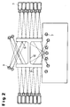
- Figure 1 shows a cross section of the overall arrangement of the cooling device with an upper 1, lower 2 and side 3 Cooling area.
- the rolling stock to be cooled is transferred via a roller table 4 from the rolling mill after the finish stitch through the cooling device guided.
- a roller table 4 from the rolling mill after the finish stitch through the cooling device guided.
- the spray angles are schematic in Figure 2 for a double T-beam shown.
- the amount of cooling medium applied depends on the profile to be cooled the profile size and shape by switching on or off of the nozzles across the cross-section and in the longitudinal direction adjusted without having to change the tool. This makes it possible to have an optimally adapted spray pattern to create and individual profiles of a profile row without losses cooling by spraying past the profile.
- the individual nozzles 7 are outside the profile range located pivot points and optionally stepless rotatable or fixed.
- the nozzle assemblies are for cooling the flange outer sides rotatable and / or slidably arranged.
- the nozzles for cooling from the Roller table out are fixed.
- the proposed cooling device is not only used for steel beams of different gradations and different Guys. Particularly suitable for profiles of more complicated shapes this cooling arrangement.
- Figure 3 shows the setting of the nozzles using the example of a pit expansion profile 6. By controlled Use only certain nozzles at certain angles every section of the profile can be cooled in a defined manner.
- one controlled cooling of the flange outer sides 8 achieved by an angular adjustment of the nozzles ( Figure 4) or by a horizontal linear guide ( Figure 5) of the nozzles.
- FIG 4 is the adjustment of the position of the respective nozzles 7 of the side cooling area 3 and their angle in With regard to two double-T beams of different types 5 a and 5 b and various sizes or a pit expansion profile 6 is shown schematically.
- the angle adjustment is achieved in that the cooling of the outer sides the flanges 8 through a plurality of nozzles 7 arranged one above the other takes place on an outside of the profile range Pivot point and are continuously rotatable.
- the arrangement can be adjusted so that it is at the bottom edge all possible profiles due to the large radius is adjusted so as not to spray past the flange.
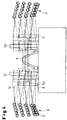
- FIG. 5 shows schematically in cross section a lateral nozzle arrangement 3, which extends in the longitudinal direction continues.
- the nozzle arrangement is horizontal as a whole slidable.
- the spraying effect is above that to be set Distance, the number of nozzles 7 and a targeted switching on and off individual nozzles reached.
- Die Cooling capacity or the heat transfer coefficient is determined by the Variation of the nozzle pressure set. It is conceivable that the functions of angle adjustment and linear guidance be combined.
- Figures 6 a and b illustrate the cooling of the undersides of a Double-T beam through nozzles from the roller conveyor, i.e. of the lower nozzle assembly 2, it can be seen that the Nozzle arrangement on different profile levels as well as on carriers of different types with different large web areas and corresponding flange areas is customizable.
- the device cannot only be used for double-T beams or Pit expansion profiles can be used. It is also possible use for rails or angled profiles.
Landscapes
- Chemical & Material Sciences (AREA)
- Engineering & Computer Science (AREA)
- Mechanical Engineering (AREA)
- Physics & Mathematics (AREA)
- Thermal Sciences (AREA)
- Crystallography & Structural Chemistry (AREA)
- Materials Engineering (AREA)
- Metallurgy (AREA)
- Organic Chemistry (AREA)
- Heat Treatments In General, Especially Conveying And Cooling (AREA)
- Metal Rolling (AREA)
- Heat Treatment Of Steel (AREA)
Applications Claiming Priority (2)
| Application Number | Priority Date | Filing Date | Title |
|---|---|---|---|
| DE19757485A DE19757485A1 (de) | 1997-12-23 | 1997-12-23 | Vorrichtung zum kontrollierten Abkühlen von warmgewalzten Profilen, insbesondere Trägern, direkt aus der Walzhitze |
| DE19757485 | 1997-12-23 |
Publications (2)
| Publication Number | Publication Date |
|---|---|
| EP0925855A2 true EP0925855A2 (fr) | 1999-06-30 |
| EP0925855A3 EP0925855A3 (fr) | 2000-08-02 |
Family
ID=7853147
Family Applications (1)
| Application Number | Title | Priority Date | Filing Date |
|---|---|---|---|
| EP98124114A Withdrawn EP0925855A3 (fr) | 1997-12-23 | 1998-12-18 | Dispositif pour le refroidissement contrôlé de profilés laminés à chaud, en particulier de poutres, directement à partir de la température de laminage |
Country Status (4)
| Country | Link |
|---|---|
| US (1) | US6170284B1 (fr) |
| EP (1) | EP0925855A3 (fr) |
| JP (1) | JPH11254022A (fr) |
| DE (1) | DE19757485A1 (fr) |
Families Citing this family (8)
| Publication number | Priority date | Publication date | Assignee | Title |
|---|---|---|---|---|
| DE10352622A1 (de) * | 2003-11-12 | 2005-06-16 | Bayerische Motoren Werke Ag | Verfahren und Vorrichtung zum Abschrecken von Werkstücken |
| JP5309684B2 (ja) * | 2008-05-13 | 2013-10-09 | 株式会社Ihi | ワークの冷却方法及びワークの冷却装置 |
| KR101129845B1 (ko) | 2009-10-29 | 2012-03-23 | 현대제철 주식회사 | 트랙 슈용 냉각장치 |
| CN101804422B (zh) * | 2010-02-10 | 2011-10-26 | 东北大学 | 一种大型h型钢轧后超快速冷却装置 |
| JP6515370B2 (ja) * | 2014-05-29 | 2019-05-22 | 株式会社Ihi | 冷却装置及び多室型熱処理装置 |
| JP6390813B2 (ja) † | 2016-03-02 | 2018-09-19 | 新日鐵住金株式会社 | 低温用h形鋼及びその製造方法 |
| WO2019122986A1 (fr) * | 2017-12-22 | 2019-06-27 | Arcelormittal | Laminoir à profilés d'acier |
| CN113375531B (zh) * | 2021-05-14 | 2023-11-03 | 南京钢铁股份有限公司 | 一种淬火机喷嘴打击角度测量工具及其制造方法、使用方法 |
Citations (9)
| Publication number | Priority date | Publication date | Assignee | Title |
|---|---|---|---|---|
| DE2148722A1 (de) * | 1970-10-02 | 1972-05-10 | Wendel Sidelor | Verfahren zur Waermebehandlung von Schienen mit einer hohen Widerstandsfaehigkeit gegen Abnutzung und dadurch hergestellte Schienen |
| JPS62188726A (ja) * | 1986-02-13 | 1987-08-18 | Nippon Kokan Kk <Nkk> | 不等辺不等厚山形鋼の冷却装置及び冷却方法 |
| DE8810085U1 (de) * | 1988-08-08 | 1988-10-20 | Elhaus, Friedrich Wilhelm, Dipl.-Ing., 7703 Rielasingen-Worblingen | Sprühwasser-Abschreckvorrichtung für Strangpreßprofile |
| EP0462783A2 (fr) * | 1990-06-21 | 1991-12-27 | Nippon Steel Corporation | Procédé et dispositif pour fabriquer des profiles d'acier en double T, à âme mince |
| WO1992019395A1 (fr) * | 1991-04-29 | 1992-11-12 | Bertin & Cie | Procede et dispositif de refroidissement d'un profile en cours de laminage |
| EP0578607A1 (fr) * | 1992-06-19 | 1994-01-12 | Alusuisse-Lonza Services Ag | Dispositif de pulvérisation pour le refroidissement de profilés |
| JPH0657327A (ja) * | 1992-08-10 | 1994-03-01 | Kawasaki Steel Corp | 靱性・強度に富んだh形鋼の製造方法 |
| JPH07108316A (ja) * | 1993-10-12 | 1995-04-25 | Nippon Steel Corp | H形鋼の冷却方法および装置 |
| EP0794022A2 (fr) * | 1996-03-08 | 1997-09-10 | Sms Schloemann-Siemag Aktiengesellschaft | Procédé, dispositif et agent pour le refroidissement de profilés |
Family Cites Families (6)
| Publication number | Priority date | Publication date | Assignee | Title |
|---|---|---|---|---|
| US3997376A (en) * | 1974-06-19 | 1976-12-14 | Midland-Ross Corporation | Spray mist cooling method |
| SE437675B (sv) * | 1981-05-14 | 1985-03-11 | Asea Ab | Kylanordning for avlanga kroppar |
| CA1193176A (fr) | 1982-07-06 | 1985-09-10 | Robert J. Ackert | Methode de production de rails de chemin de fer de meilleure qualite par refroidissement accelere a la sortie du laminoir |
| LU84999A1 (fr) | 1983-09-12 | 1985-06-04 | Arbed | Procede et dispositif de refroidissement de produits metalliques lamines |
| US4497180A (en) * | 1984-03-29 | 1985-02-05 | National Steel Corporation | Method and apparatus useful in cooling hot strip |
| DE4237991A1 (de) * | 1992-11-11 | 1994-05-19 | Schloemann Siemag Ag | Verfahren und Vorrichtung zur Abkühlung von warmgewalzten Profilen insbesondere von Schienen |
-
1997
- 1997-12-23 DE DE19757485A patent/DE19757485A1/de not_active Withdrawn
-
1998
- 1998-12-17 US US09/213,608 patent/US6170284B1/en not_active Expired - Lifetime
- 1998-12-18 EP EP98124114A patent/EP0925855A3/fr not_active Withdrawn
- 1998-12-21 JP JP10363344A patent/JPH11254022A/ja active Pending
Patent Citations (9)
| Publication number | Priority date | Publication date | Assignee | Title |
|---|---|---|---|---|
| DE2148722A1 (de) * | 1970-10-02 | 1972-05-10 | Wendel Sidelor | Verfahren zur Waermebehandlung von Schienen mit einer hohen Widerstandsfaehigkeit gegen Abnutzung und dadurch hergestellte Schienen |
| JPS62188726A (ja) * | 1986-02-13 | 1987-08-18 | Nippon Kokan Kk <Nkk> | 不等辺不等厚山形鋼の冷却装置及び冷却方法 |
| DE8810085U1 (de) * | 1988-08-08 | 1988-10-20 | Elhaus, Friedrich Wilhelm, Dipl.-Ing., 7703 Rielasingen-Worblingen | Sprühwasser-Abschreckvorrichtung für Strangpreßprofile |
| EP0462783A2 (fr) * | 1990-06-21 | 1991-12-27 | Nippon Steel Corporation | Procédé et dispositif pour fabriquer des profiles d'acier en double T, à âme mince |
| WO1992019395A1 (fr) * | 1991-04-29 | 1992-11-12 | Bertin & Cie | Procede et dispositif de refroidissement d'un profile en cours de laminage |
| EP0578607A1 (fr) * | 1992-06-19 | 1994-01-12 | Alusuisse-Lonza Services Ag | Dispositif de pulvérisation pour le refroidissement de profilés |
| JPH0657327A (ja) * | 1992-08-10 | 1994-03-01 | Kawasaki Steel Corp | 靱性・強度に富んだh形鋼の製造方法 |
| JPH07108316A (ja) * | 1993-10-12 | 1995-04-25 | Nippon Steel Corp | H形鋼の冷却方法および装置 |
| EP0794022A2 (fr) * | 1996-03-08 | 1997-09-10 | Sms Schloemann-Siemag Aktiengesellschaft | Procédé, dispositif et agent pour le refroidissement de profilés |
Non-Patent Citations (3)
| Title |
|---|
| PATENT ABSTRACTS OF JAPAN vol. 012, no. 040 (C-474), 5. Februar 1988 (1988-02-05) -& JP 62 188726 A (NIPPON KOKAN KK), 18. August 1987 (1987-08-18) * |
| PATENT ABSTRACTS OF JAPAN vol. 018, no. 291 (C-1208), 3. Juni 1994 (1994-06-03) -& JP 06 057327 A (KAWASAKI STEEL CORP), 1. März 1994 (1994-03-01) * |
| PATENT ABSTRACTS OF JAPAN vol. 1995, no. 07, 31. August 1995 (1995-08-31) -& JP 07 108316 A (NIPPON STEEL CORP), 25. April 1995 (1995-04-25) * |
Also Published As
| Publication number | Publication date |
|---|---|
| EP0925855A3 (fr) | 2000-08-02 |
| US6170284B1 (en) | 2001-01-09 |
| DE19757485A1 (de) | 1999-06-24 |
| JPH11254022A (ja) | 1999-09-21 |
Similar Documents
| Publication | Publication Date | Title |
|---|---|---|
| EP1052295B1 (fr) | Méthode de fabrication d'éléments structurels dans la construction automobile | |
| EP3303642B1 (fr) | Procédé de refroidissement sans contact de tôles d'acier et dispositif à cet effet | |
| DE102016102093B3 (de) | Durchlaufkühlvorrichtung und Verfahren zum Abkühlen eines Metallbandes | |
| EP0618020A1 (fr) | Procédé et dispositif pour laminer d'un feuillard | |
| DE102007043154A1 (de) | Verfahren und Vorrichtung zum Härten von Profilen | |
| EP1948834B1 (fr) | Procede et dispositif pour former en continu une structure de bainite dans un acier au carbone, en particulier dans un acier feuillard | |
| EP0070409B1 (fr) | Procédé et dispositif pour la trempe par induction de pièces élongées à paroi mince | |
| WO2003012151A1 (fr) | Procede de refroidissement de pieces, en particulier de produits lamines profiles en acier qualite rail | |
| DE1809859A1 (de) | Verfahren und Vorrichtung zum Haerten von geraden Glasscheiben | |
| EP3420111B1 (fr) | Procédé de traitement thermique ciblé sur les zones d'une pièce | |
| DE102015113056B4 (de) | Verfahren zum kontaktlosen Kühlen von Stahlblechen und Vorrichtung hierfür | |
| DE102009060256A1 (de) | Verfahren zum Warmwalzen einer Bramme und Warmwalzwerk | |
| AT410549B (de) | Vorrichtung zum vergüten von walzgut mit grosser länge | |
| EP0925855A2 (fr) | Dispositif pour le refroidissement contrÔlé de profilés laminés à chaud, en particulier de poutres, directement à partir de la température de laminage | |
| DE10327383A1 (de) | Verfahren und Anlage zur Herstellung von Warmband mit Dualphasengefüge | |
| EP3262202B1 (fr) | Installation pour la fabrication en série de pièces moulées de tôle durcies sous presse et protégées contre la corrosion, comprenant un système de refroidissement pour le refroidissement intermédiaire des plaques | |
| WO2001009395A1 (fr) | Procede de durcissage d'au moins une surface d'une paroi d'un element de construction et dispositif permettant sa realisation | |
| EP0904865B1 (fr) | Procédé et dispositif de formage d'une bande métallique ayant des zones d'épaisseur différentes dans sa largeur | |
| EP0616646B1 (fr) | Procede de traitement thermique de produits metalliques | |
| CH621364A5 (en) | Process and equipment for the heat treatment of switch components | |
| DE2543750A1 (de) | Verfahren und vorrichtung zur verbesserung der qualitaet bei profilstahl | |
| EP3862710B1 (fr) | Four de chauffage partiel des composants métalliques | |
| EP0881004A2 (fr) | Procédé pour laminer des profilés en acier | |
| EP2567763B1 (fr) | Outil de formage doté de forages de canal de refroidissement ramifiés à l'intérieur des éléments d'outil | |
| DE3234299C2 (de) | Verfahren zum Oberflächenhärten von Werkstücken und Vorrichtung zum Durchführen des Verfahrens |
Legal Events
| Date | Code | Title | Description |
|---|---|---|---|
| PUAI | Public reference made under article 153(3) epc to a published international application that has entered the european phase |
Free format text: ORIGINAL CODE: 0009012 |
|
| 17P | Request for examination filed |
Effective date: 19981218 |
|
| AK | Designated contracting states |
Kind code of ref document: A2 Designated state(s): AT BE CH DE DK ES FI FR GB GR IE IT LI LU NL PT SE |
|
| AX | Request for extension of the european patent |
Free format text: AL;LT;LV;MK;RO;SI |
|
| RAP1 | Party data changed (applicant data changed or rights of an application transferred) |
Owner name: SMS DEMAG AG |
|
| PUAL | Search report despatched |
Free format text: ORIGINAL CODE: 0009013 |
|
| AK | Designated contracting states |
Kind code of ref document: A3 Designated state(s): AT BE CH CY DE DK ES FI FR GB GR IE IT LI LU MC NL PT SE |
|
| AX | Request for extension of the european patent |
Free format text: AL;LT;LV;MK;RO;SI |
|
| RIC1 | Information provided on ipc code assigned before grant |
Free format text: 7B 21B 45/02 A, 7C 21D 1/667 B, 7C 21D 1/02 B |
|
| AKX | Designation fees paid |
Free format text: AT BE CH DE DK ES FI FR GB GR IE IT LI LU NL PT SE |
|
| 17Q | First examination report despatched |
Effective date: 20020412 |
|
| STAA | Information on the status of an ep patent application or granted ep patent |
Free format text: STATUS: THE APPLICATION IS DEEMED TO BE WITHDRAWN |
|
| 18D | Application deemed to be withdrawn |
Effective date: 20021023 |