EP0925855A2 - Device for the controlled cooling from the rolling temperature of hot-rolled profiles, in particular beams - Google Patents
Device for the controlled cooling from the rolling temperature of hot-rolled profiles, in particular beams Download PDFInfo
- Publication number
- EP0925855A2 EP0925855A2 EP98124114A EP98124114A EP0925855A2 EP 0925855 A2 EP0925855 A2 EP 0925855A2 EP 98124114 A EP98124114 A EP 98124114A EP 98124114 A EP98124114 A EP 98124114A EP 0925855 A2 EP0925855 A2 EP 0925855A2
- Authority
- EP
- European Patent Office
- Prior art keywords
- cooling
- nozzles
- profile
- profiles
- nozzle
- Prior art date
- Legal status (The legal status is an assumption and is not a legal conclusion. Google has not performed a legal analysis and makes no representation as to the accuracy of the status listed.)
- Withdrawn
Links
- 238000001816 cooling Methods 0.000 title claims abstract description 83
- 238000005096 rolling process Methods 0.000 title claims description 10
- 239000007921 spray Substances 0.000 claims abstract description 19
- 239000002826 coolant Substances 0.000 claims abstract description 12
- 229910000831 Steel Inorganic materials 0.000 claims description 8
- 239000010959 steel Substances 0.000 claims description 8
- XLYOFNOQVPJJNP-UHFFFAOYSA-N water Substances O XLYOFNOQVPJJNP-UHFFFAOYSA-N 0.000 claims description 4
- 238000005507 spraying Methods 0.000 claims description 3
- 230000007704 transition Effects 0.000 claims description 3
- 239000002131 composite material Substances 0.000 claims description 2
- 239000000443 aerosol Substances 0.000 claims 1
- 239000012809 cooling fluid Substances 0.000 claims 1
- 238000003491 array Methods 0.000 abstract 1
- 238000009434 installation Methods 0.000 abstract 1
- 238000000034 method Methods 0.000 description 12
- 230000008569 process Effects 0.000 description 10
- 229910000734 martensite Inorganic materials 0.000 description 9
- 230000000694 effects Effects 0.000 description 8
- 239000000463 material Substances 0.000 description 6
- 239000000969 carrier Substances 0.000 description 4
- 238000009826 distribution Methods 0.000 description 4
- 230000000712 assembly Effects 0.000 description 3
- 238000000429 assembly Methods 0.000 description 3
- 230000008859 change Effects 0.000 description 3
- 238000005496 tempering Methods 0.000 description 3
- 238000010438 heat treatment Methods 0.000 description 2
- 230000009466 transformation Effects 0.000 description 2
- 230000006978 adaptation Effects 0.000 description 1
- 238000005275 alloying Methods 0.000 description 1
- 238000004380 ashing Methods 0.000 description 1
- 230000015572 biosynthetic process Effects 0.000 description 1
- 239000000498 cooling water Substances 0.000 description 1
- 238000000265 homogenisation Methods 0.000 description 1
- 238000005098 hot rolling Methods 0.000 description 1
- 230000006872 improvement Effects 0.000 description 1
- 229910001562 pearlite Inorganic materials 0.000 description 1
- 230000035515 penetration Effects 0.000 description 1
- 230000002093 peripheral effect Effects 0.000 description 1
- 238000010791 quenching Methods 0.000 description 1
- 230000000171 quenching effect Effects 0.000 description 1
- 230000009467 reduction Effects 0.000 description 1
- 230000000630 rising effect Effects 0.000 description 1
- 230000000930 thermomechanical effect Effects 0.000 description 1
- 238000011282 treatment Methods 0.000 description 1
- 229910000859 α-Fe Inorganic materials 0.000 description 1
Images


Classifications
-
- B—PERFORMING OPERATIONS; TRANSPORTING
- B21—MECHANICAL METAL-WORKING WITHOUT ESSENTIALLY REMOVING MATERIAL; PUNCHING METAL
- B21B—ROLLING OF METAL
- B21B45/00—Devices for surface or other treatment of work, specially combined with or arranged in, or specially adapted for use in connection with, metal-rolling mills
- B21B45/02—Devices for surface or other treatment of work, specially combined with or arranged in, or specially adapted for use in connection with, metal-rolling mills for lubricating, cooling, or cleaning
- B21B45/0203—Cooling
- B21B45/0209—Cooling devices, e.g. using gaseous coolants
- B21B45/0215—Cooling devices, e.g. using gaseous coolants using liquid coolants, e.g. for sections, for tubes
-
- C—CHEMISTRY; METALLURGY
- C21—METALLURGY OF IRON
- C21D—MODIFYING THE PHYSICAL STRUCTURE OF FERROUS METALS; GENERAL DEVICES FOR HEAT TREATMENT OF FERROUS OR NON-FERROUS METALS OR ALLOYS; MAKING METAL MALLEABLE, e.g. BY DECARBURISATION OR TEMPERING
- C21D1/00—General methods or devices for heat treatment, e.g. annealing, hardening, quenching or tempering
- C21D1/02—Hardening articles or materials formed by forging or rolling, with no further heating beyond that required for the formation
-
- C—CHEMISTRY; METALLURGY
- C21—METALLURGY OF IRON
- C21D—MODIFYING THE PHYSICAL STRUCTURE OF FERROUS METALS; GENERAL DEVICES FOR HEAT TREATMENT OF FERROUS OR NON-FERROUS METALS OR ALLOYS; MAKING METAL MALLEABLE, e.g. BY DECARBURISATION OR TEMPERING
- C21D1/00—General methods or devices for heat treatment, e.g. annealing, hardening, quenching or tempering
- C21D1/62—Quenching devices
- C21D1/667—Quenching devices for spray quenching
-
- C—CHEMISTRY; METALLURGY
- C21—METALLURGY OF IRON
- C21D—MODIFYING THE PHYSICAL STRUCTURE OF FERROUS METALS; GENERAL DEVICES FOR HEAT TREATMENT OF FERROUS OR NON-FERROUS METALS OR ALLOYS; MAKING METAL MALLEABLE, e.g. BY DECARBURISATION OR TEMPERING
- C21D9/00—Heat treatment, e.g. annealing, hardening, quenching or tempering, adapted for particular articles; Furnaces therefor
- C21D9/0068—Heat treatment, e.g. annealing, hardening, quenching or tempering, adapted for particular articles; Furnaces therefor for particular articles not mentioned below
Definitions
- the invention relates to a device for controlled Cooling of hot-rolled profiles, especially beams Steel, straight from the rolling heat.
- thermomechanical rolling especially when rolling profiles, however Limits are set by the load capacity of the roll stands these processes have high levels of deformation in comparison require low temperatures.
- QST Quenching and Self Tempering, hardening and self-tempering
- the components For example, rolled profiles, after the finish stitch from the Roll heat quenched out with water. Before the core of the Workpiece has cooled, the cooling is interrupted and the structure in the edge area due to the core still present Heat left.
- this can Process will be influenced, in particular, about the Cooling time set the depth of the layer (penetration depth), in which martensite forms.
- the starting process takes place, in which the previously formed by the residual heat in the profile Martensite layer is left on.
- the temperature is rising again above the martensite start temperature.
- the martensitic area relaxes and thus a material high strength with good toughness.
- the subsequent cooling process in air forms inside the cross section bainitic and / or (fine) pearlitic Structure.
- the material is to be cooled without forming martensite, is the surface temperature via the cooling time and cooling intensity the profiles cooled so that the martensite start temperature is not undercut. Homogenization also takes place here the temperature distribution a tempering after End of forced cooling. After the start-up process results an improvement in the mechanical properties the setting of a fine pearlitic and ferritic structure.
- the profile or the surfaces to be cooled be targeted with the cooling medium.
- a device for cooling carriers is from the European Patent 0 140 026 known.
- the application of Coolant is passed through so-called cool boxes. These are sprayed with openings at equal intervals provided by coolant.
- For cooling the outer or inner areas of the carrier are the boxes for the outer surface at least as large as the height of the flanges. Cover the boxes to cool the inner flanges the entire inner surface of the flanges and at least 70% the web area. It is possible to change the curvature behavior too to influence with asymmetrical profiles.
- European patent 0 462 783 discloses a method and a device for heat treatment thin-walled Double T profiles.
- the rolled products are forced-cooled between the rolling processes.
- the cooling device itself consists of a large number of nozzles arranged one above the other are. They are operated with water and are different can be switched on and off.
- the cooling device described cools the flange outer sides of the Profiles. This is done with the purpose of the outer surface of the Beam to final temperature before final hot rolling cool from 700 ° C or less. By repetition The forced cooling with water becomes the microstructure of the Flange surface converted to a certain depth.
- the present invention has for its object a Cooling device for finished rolled profiles, in particular Steel girder to be provided when changing the rolling program to different geometries and sizes of the profiles adjustable and uniform cooling of the profile or the cooling of defined sections guaranteed.
- the core of the invention is the setting of an optimally adapted Spray pattern of the cooling device on different profile geometries, in that the cooling device has cooling areas, each with a cooling area from the one to be cooled Profile viewed from this is arranged above, and the cooling areas can be used individually or in combination are, with a cooling area each from at least one nozzle or a composite nozzle, the nozzles individually or are controllable in the network, d. H . the individual cooling areas are controllable.
- the adaptation of the cooling effect is achieved in detail by varying the nozzle distance to the profile, by controlled Setting the spray pressure by means of stepless Individual nozzles can be rotated and switched on and off of the individual nozzles.
- the nozzle assembly consists of several nozzles, their outlet openings span a plane or form a straight line. Due to the differently designed nozzle assemblies as surfaces or rows of nozzles and the high variability of the nozzles becomes one reached flexible adjustment of the cooling device, wherein the different sections of the profiles are cooled differently and the cooling capacity can be adapted to the requirements can.
- the proposed cooling device can be different shaped profiles, one after the other the device run through without cooling the system.
- cooling processes to minimize residual stress in the Workpiece body through simultaneous structural transformation in the material to pull as well as cooling processes to set a pearlitic Structure.
- the cooling device can optimally match the beam or profile dimensions be adjusted.
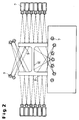
- Figure 1 shows a cross section of the overall arrangement of the cooling device with an upper 1, lower 2 and side 3 Cooling area.
- the rolling stock to be cooled is transferred via a roller table 4 from the rolling mill after the finish stitch through the cooling device guided.
- a roller table 4 from the rolling mill after the finish stitch through the cooling device guided.
- the spray angles are schematic in Figure 2 for a double T-beam shown.
- the amount of cooling medium applied depends on the profile to be cooled the profile size and shape by switching on or off of the nozzles across the cross-section and in the longitudinal direction adjusted without having to change the tool. This makes it possible to have an optimally adapted spray pattern to create and individual profiles of a profile row without losses cooling by spraying past the profile.
- the individual nozzles 7 are outside the profile range located pivot points and optionally stepless rotatable or fixed.
- the nozzle assemblies are for cooling the flange outer sides rotatable and / or slidably arranged.
- the nozzles for cooling from the Roller table out are fixed.
- the proposed cooling device is not only used for steel beams of different gradations and different Guys. Particularly suitable for profiles of more complicated shapes this cooling arrangement.
- Figure 3 shows the setting of the nozzles using the example of a pit expansion profile 6. By controlled Use only certain nozzles at certain angles every section of the profile can be cooled in a defined manner.
- one controlled cooling of the flange outer sides 8 achieved by an angular adjustment of the nozzles ( Figure 4) or by a horizontal linear guide ( Figure 5) of the nozzles.
- FIG 4 is the adjustment of the position of the respective nozzles 7 of the side cooling area 3 and their angle in With regard to two double-T beams of different types 5 a and 5 b and various sizes or a pit expansion profile 6 is shown schematically.
- the angle adjustment is achieved in that the cooling of the outer sides the flanges 8 through a plurality of nozzles 7 arranged one above the other takes place on an outside of the profile range Pivot point and are continuously rotatable.
- the arrangement can be adjusted so that it is at the bottom edge all possible profiles due to the large radius is adjusted so as not to spray past the flange.
- FIG. 5 shows schematically in cross section a lateral nozzle arrangement 3, which extends in the longitudinal direction continues.
- the nozzle arrangement is horizontal as a whole slidable.
- the spraying effect is above that to be set Distance, the number of nozzles 7 and a targeted switching on and off individual nozzles reached.
- Die Cooling capacity or the heat transfer coefficient is determined by the Variation of the nozzle pressure set. It is conceivable that the functions of angle adjustment and linear guidance be combined.
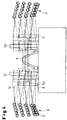
- Figures 6 a and b illustrate the cooling of the undersides of a Double-T beam through nozzles from the roller conveyor, i.e. of the lower nozzle assembly 2, it can be seen that the Nozzle arrangement on different profile levels as well as on carriers of different types with different large web areas and corresponding flange areas is customizable.
- the device cannot only be used for double-T beams or Pit expansion profiles can be used. It is also possible use for rails or angled profiles.
Abstract
Description
Die Erfindung betrifft eine Vorrichtung zum kontrollierten Abkühlen von warmgewalzten Profilen, insbesondere Trägern aus Stahl, direkt aus der Walzhitze.The invention relates to a device for controlled Cooling of hot-rolled profiles, especially beams Steel, straight from the rolling heat.
Es ist bekannt, die mechanischen Eigenschaften von Werkstoffen, insbesondere Stahl, durch Wärmebehandlungen und/oder durch den Zusatz von Legierungselementen zu beeinflussen. Der unbegrenzten Anwendung des bekannten thermomechanischen Walzens, insbesondere bei dem Walzen von Profilen, sind jedoch Grenzen gesetzt durch die Belastbarkeit der Walzgerüste, da diese Verfahren hohe Verformungsgrade bei vergleichsweise niedrigen Temperaturen voraussetzen.It is known the mechanical properties of materials, especially steel, by heat treatments and / or influenced by the addition of alloying elements. Of the unlimited use of known thermomechanical rolling, especially when rolling profiles, however Limits are set by the load capacity of the roll stands these processes have high levels of deformation in comparison require low temperatures.
Durch das sogenannte QST-Verfahren (QST: Quenching und Self Tempering, Härten und Selbstanlassen) können die mechanischen Eigenschaften beeinflußt werden. Hierbei werden die Bauteile, beispielsweise Walzprofile, nach dem Fertigstich aus der Walzhitze heraus mit Wasser abgeschreckt. Bevor der Kern des Werkstücks abgekühlt ist, wird die Kühlung unterbrochen und das Gefüge im Randbereich durch die im Kern noch vorhandene Wärme angelassen.Through the so-called QST process (QST: Quenching and Self Tempering, hardening and self-tempering) can be mechanical Properties are affected. The components, For example, rolled profiles, after the finish stitch from the Roll heat quenched out with water. Before the core of the Workpiece has cooled, the cooling is interrupted and the structure in the edge area due to the core still present Heat left.
Bei der Behandlung von Stählen werden während des Aschreckvorgangs die Materialoberfläche und die darunter befindlichen Schichten je nach Kühldauer unter die Martensit-Starttemperatur abgekühlt, was die Bildung von Martensit in den Randzonen zur Folge hat. Über die Kühlzeit und das Kühlmedium kann dieser Vorgang beeinflußt werden, insbesondere wird über die Kühlzeit die Tiefe der Schicht (Eindringtiefe) eingestellt, in der sich Martensit bildet.In the treatment of steels during the ashing process the material surface and those underneath Depending on the cooling time, layers below the martensite start temperature cooled down, causing the formation of martensite in the peripheral zones has the consequence. About the cooling time and the cooling medium, this can Process will be influenced, in particular, about the Cooling time set the depth of the layer (penetration depth), in which martensite forms.
Nach dem Ende dieser Zwangskühlung erfolgt dann der Anlaßvorgang, bei dem durch die Restwärme im Profil die zuvor gebildete Martensitschicht angelassen wird. Die Temperatur steigt wieder über die Martensit-Starttemperatur an. Hierbei wird der martensitische Bereich entspannt und somit ein Material hoher Festigkeit bei gleichzeitig guter Zähigkeit eingestellt.After this forced cooling ends, the starting process takes place, in which the previously formed by the residual heat in the profile Martensite layer is left on. The temperature is rising again above the martensite start temperature. Here will the martensitic area relaxes and thus a material high strength with good toughness.
Bei dem sich anschließenden Abkühlvorgang an Luft bildet sich im Inneren des Querschnitts bainitisches und/oder (fein)-perlitisches Gefüge.The subsequent cooling process in air forms inside the cross section bainitic and / or (fine) pearlitic Structure.
Soll das Material abgekühlt werden, ohne Martensit zu bilden, wird über die Kühlzeit und Kühlintensität die Oberflächentemperatur der Profile so abgekühlt, daß die Martensit-Starttemperatur nicht unterschritten wird. Auch hier erfolgt zur Homogenisierung der Temperaturverteilung ein Anlassen nach dem Ende der Zwangskühlung. Nach -lauf des Anlaßvorgangs ergibt sich eine Verbesserung der mechanischen Eigenschaften durch die Einstellung eines beispielsweise fein-perlitischen und ferritischen Gefüges.If the material is to be cooled without forming martensite, is the surface temperature via the cooling time and cooling intensity the profiles cooled so that the martensite start temperature is not undercut. Homogenization also takes place here the temperature distribution a tempering after End of forced cooling. After the start-up process results an improvement in the mechanical properties the setting of a fine pearlitic and ferritic structure.
Zur gleichmäßigen Einstellung der gewünschten Eigenschaften ist es wichtig, daß das Profil bzw. die zu kühlenden Flächen gezielt mit dem Kühlmedium beaufschlagt werden.For uniform setting of the desired properties it is important that the profile or the surfaces to be cooled be targeted with the cooling medium.
Eine Vorrichtung zum Abkühlen von Trägern ist aus dem europäischen Patent 0 140 026 bekannt. Die Beaufschlagung mit Kühlflüssigkeit erfolgt im Durchlauf über sog. Kühlkästen. Diese sind mit Öffnungen in gleichen Abständen zum Versprühen von Kühlflüssigkeit versehen. Zur Kühlung der äußeren bzw. inneren Bereiche des Trägers sind die Kästen für die Außenfläche mindestens so groß ausgebildet wie die Höhe der Flansche. Zur Kühlung der inneren Flansche überdecken die Kästen die gesamte innere Fläche der Flansche sowie mindestens 70% der Stegfläche. Es ist möglich, das Krümmungsverhalten auch bei unsymmetrischen Profilen zu beeinflussen.A device for cooling carriers is from the European Patent 0 140 026 known. The application of Coolant is passed through so-called cool boxes. These are sprayed with openings at equal intervals provided by coolant. For cooling the outer or inner areas of the carrier are the boxes for the outer surface at least as large as the height of the flanges. Cover the boxes to cool the inner flanges the entire inner surface of the flanges and at least 70% the web area. It is possible to change the curvature behavior too to influence with asymmetrical profiles.
Als Nachteil erweist sich hier, daß bei unterschiedlichen Geometrien der Profile bei Änderung des Walzprogramms eine Anpassung der inneren Kühlkästen notwendig ist. Weiterhin ist dieses Verfahren hauptsächlich bei großen Trägern einsetzbar, da ein Werkzeug von oben und unten zwischen die Flansche gefahren wird. Bei kleinen Trägern ist dies aufgrund des kleinen Bauraums nicht oder nur sehr eingeschränkt möglich.The disadvantage here is that with different Geometries of the profiles when changing the rolling program Adjustment of the inner coolers is necessary. Still is this method can mainly be used for large beams, because a tool from above and below between the flanges is driven. For small carriers, this is due to the small space or not very possible.
Da die Beaufschlagung des Trägers mit Kühlwasser für alle Stellen einer Fläche näherungsweise gleich erfolgt und aufgrund der Konstruktion der Kühlkästen einzelne Öffnungen oder Reihen nicht abgeschaltet werden können, ist eine möglichst homogene Temperaturverteilung im Querschnitt erforderlich. Diese Temperaturverteilung muß daher in einem gewissen Maß bereits während des Walzvorgangs mit Hilfe einer selektiven Kühlung der Übergangszone Flansch-Steg eingestellt werden. Ferner ist eine Kühlung hinsichtlich der Reduzierung der Eigenspannungen im Träger mit dieser Vorrichtung nicht möglich.Since the application of cooling water to the wearer for everyone Make an area approximately the same and due the design of the cooling boxes individual openings or Rows cannot be switched off is one possible homogeneous temperature distribution in the cross section required. This temperature distribution must therefore to a certain extent already during the rolling process with the help of a selective one Cooling of the transition zone flange-web can be set. There is also cooling with regard to the reduction of residual stresses not possible in the carrier with this device.
Die europäische Patentschrift 0 462 783 offenbart ein Verfahren und eine Vorrichtung zur Wärmebehandlung dünnwandiger Doppel-T-Profile. Es erfolgt eine Zwangskühlung der Walzprodukte zwischen den Walzvorgängen. Die Kühlvorrichtung selbst besteht aus einer Vielzahl von Düsen, die übereinander angeordnet sind. Sie werden mit Wasser betrieben und sind unterschiedlich zu- und abschaltbar. Die beschriebene Kühlvorrichtung kühlt allerdings allein die Flanschaußenseiten der Profile. Dies geschieht mit dem Zweck, die Außenfläche der Träger vor dem abschließenden Warmwalzen auf eine Temperatur von 700°C oder weniger abzukühlen. Durch eine Wiederholung der Zwangskühlung mit Wasser wird die Mikrostruktur der Flanschoberfläche bis zu einer bestimmten Tiefe umgewandelt.European patent 0 462 783 discloses a method and a device for heat treatment thin-walled Double T profiles. The rolled products are forced-cooled between the rolling processes. The cooling device itself consists of a large number of nozzles arranged one above the other are. They are operated with water and are different can be switched on and off. The cooling device described cools the flange outer sides of the Profiles. This is done with the purpose of the outer surface of the Beam to final temperature before final hot rolling cool from 700 ° C or less. By repetition The forced cooling with water becomes the microstructure of the Flange surface converted to a certain depth.
Weiterhin ist ein Kühlverfahren und -vorrichtung aus dem europäischen Patent 0 098 492 bekannt. Hierbei wird eine Vorrichtung vorgeschlagen zur Abkühlung von Stahlprofilen, hier Schienen, die durch eine Kühlvorrichtung geführt werden. Eine Variation der Kühlung bzw. eine lokale Kühlung wird durch unterschiedliche Orientierung der transportierten Schienen sowie über Ablenkbleche für das Kühlmedium erreicht.Furthermore, a cooling method and device from the European Patent 0 098 492 known. This is a device proposed for cooling steel profiles, here Rails that are passed through a cooling device. A Variation of cooling or local cooling is different Orientation of the transported rails as well reached via baffles for the cooling medium.
Der vorliegenden Erfindung liegt die Aufgabe zugrunde, eine Kühlvorrichtung für fertiggewalzte Profile, insbesondere Stahlträger, bereitzustellen, die bei Änderung des Walzprogramms auf unterschiedliche Geometrien und Größen der Profile einstellbar ist sowie eine gleichförmige Kühlung des Profils bzw. die Kühlung definierter Teilbereiche gewährleistet.The present invention has for its object a Cooling device for finished rolled profiles, in particular Steel girder to be provided when changing the rolling program to different geometries and sizes of the profiles adjustable and uniform cooling of the profile or the cooling of defined sections guaranteed.
Die Aufgabe wird durch die Merkmale der Vorrichtung nach Anspruch 1 gelöst. Vorteilhafte Ausgestaltungen der Erfindung sind in den Unteransprüchen offenbart.The object is achieved by the features of the device according to claim 1 solved. Advantageous embodiments of the invention are disclosed in the subclaims.
Kern der Erfindung ist die Einstellung eines optimal angepaßten Spritzbildes der Kühlvorrichtung an unterschiedliche Profilgeometrien, indem die Kühlvorrichtung Kühlbereiche aufweist, wobei jeweils ein Kühlbereich von dem zu kühlenden Profil aus betrachtet zu diesem oberhalb angeordnet ist, und die Kühlbereiche jeweils einzeln oder kombiniert einsetzbar sind, wobei ein Kühlbereich jeweils aus mindestens einer Düse oder einem Düsenverbund besteht, wobei die Düsen einzeln oder im Verbund steuerbar sind, d. h . die einzelnen Kühlbereiche steuerbar sind. The core of the invention is the setting of an optimally adapted Spray pattern of the cooling device on different profile geometries, in that the cooling device has cooling areas, each with a cooling area from the one to be cooled Profile viewed from this is arranged above, and the cooling areas can be used individually or in combination are, with a cooling area each from at least one nozzle or a composite nozzle, the nozzles individually or are controllable in the network, d. H . the individual cooling areas are controllable.
Die Anpassung der Kühlwirkung wird im einzelnen erreicht durch Variation des Düsenabstandes zum Profil hin, durch kontrollierte Einstellung des Spritzdrucks, durch stufenlose Verdrehbarkeit einzelner Düsen sowie durch Zu- und Abschalten der einzelnen Düsen.The adaptation of the cooling effect is achieved in detail by varying the nozzle distance to the profile, by controlled Setting the spray pressure by means of stepless Individual nozzles can be rotated and switched on and off of the individual nozzles.
Dabei wird neben der Anpassung an die Profilgeometrie über die Variation des Düsenabstands und des Düsendrucks der für eine erfolgreiche Kühlung eines Profils erforderliche Wärmeübergangskoeffizient eingestellt. Die Einstellung des gewünschten Spritzbildes erfolgt zusätzlich über die Verdrehbarkeit der Düsen sowie Zu- und Abschalten einzelner Düsen und Düsenverbunde.In addition to adapting to the profile geometry the variation of nozzle spacing and nozzle pressure for a successful cooling of a profile required heat transfer coefficient set. The setting of the desired Spray pattern also takes place via the rotatability the nozzles as well as switching individual nozzles on and off and nozzle assemblies.
Der Düsenverbund besteht aus mehreren Düsen, deren Austrittsöffnungen eine Ebene aufspannen oder eine Gerade bilden. Durch die verschieden gestalteten Düsenverbunde als Flächen oder Düsenreihen und die hohe Variabilität der Düsen wird eine flexible Einstellung der Kühlvorrichtung erreicht, wobei die verschiedenen Teilflächen der Profile unterschiedlich gekühlt und die Kühlleistung den Anforderungen angepaßt werden können.The nozzle assembly consists of several nozzles, their outlet openings span a plane or form a straight line. Due to the differently designed nozzle assemblies as surfaces or rows of nozzles and the high variability of the nozzles becomes one reached flexible adjustment of the cooling device, wherein the different sections of the profiles are cooled differently and the cooling capacity can be adapted to the requirements can.
Damit ist es möglich, bei umgeformten Walzprofilen trotz einer unterschiedlichen Temperaturverteilung über den Querschnitt nach dem Verlassen der Walzstraße eine gleichzeitige Gefügeumwandlung im Werkstoff einzustellen. Insbesondere ist es möglich, die Zwangskühlung des QST-Verfahrens im gesamten Werkstück gleichmäßig durchzufuhren. Es wird gewährleistet, daß die Randzone der Stahlprofile nach dem Kühlvorgang mit einer bestimmten Tiefe von der Oberfläche aus gesehen aus angelassenem Martensit und die Kernzone aus Perlit und/oder Ferrit besteht. This makes it possible, in spite of one, for formed rolled profiles different temperature distribution over the cross section a simultaneous after leaving the rolling mill Set structural transformation in the material. In particular is it is possible to force-cool the QST process throughout Perform workpiece evenly. It is guaranteed that the edge zone of the steel profiles after cooling with a certain depth from the surface as seen Martensite and the core zone from pearlite and / or Ferrite exists.
Mittels der vorgeschlagenen Kühlvorrichtung können unterschiedlich geformte Profile, die nacheinander die Vorrichtung durchlaufen, ohne Umbau der Anlage gekühlt werden.By means of the proposed cooling device can be different shaped profiles, one after the other the device run through without cooling the system.
Weiterhin ist es möglich, unterschiedliche Kühlstrategien ohne Umbau der Anlage im Durchlauf zu realisieren. Hierunter sind Kühlprozesse zur Minimierung von Eigenspannungen im Werkstückkörper durch gleichzeitige Gefügeumwandlung im Werkstoff zu ziehen sowie Kühlprozesse zur Einstellung eines perlitischen Gefüges.It is also possible to use different cooling strategies without Realization of the system in one go. Below are cooling processes to minimize residual stress in the Workpiece body through simultaneous structural transformation in the material to pull as well as cooling processes to set a pearlitic Structure.
Es erweist sich hierbei von Vorteil, daß sich keine Werkzeuge zwischen den Flanschen der Profile befinden. Durch die verdrehbaren Düsenhalterungen und die flexiblen Ansteuerungen kann die Kühlvorrichtung optimal an die Träger- bzw. Profilabmessung angepaßt werden.It proves advantageous here that there are no tools between the flanges of the profiles. Through the rotatable Nozzle holders and the flexible controls the cooling device can optimally match the beam or profile dimensions be adjusted.
Durch die optimale Anpassung aufgrund der hohen Variierungsmöglichkeit der einzelnen Düsen wird verhindert, daß Kühlmedium an dem zu kühlenden Bereich vorbeispritzt. Damit wird eine hohe Kühlleistung gewährleistet, Verluste an Kühlmedium werden vermieden, es entstehen keine Störeffekte an anderen Düsenanlagen.Due to the optimal adjustment due to the high degree of variation of the individual nozzles prevents cooling medium sprayed past the area to be cooled. So that will high cooling capacity ensures loss of cooling medium are avoided, there are no disturbing effects on others Nozzle systems.
Weitere Einzelheiten und Vorteile der Erfindung ergeben sich aus den Ansprüchen und der nachfolgenden Beschreibung, in der in den Zeichnungen dargestellte Ausführungsbeispiele der Erfindung näher erläutert werden. Es zeigen:
- Figur 1
- einen Querschnitt einer Gesamtanordnung der vorgeschlagenen Kühlvorrichtung;
Figur 2- eine schematische Darstellung der Sprühwinkel am Beispiel eines Doppel-T-Trägers;
Figur 3- eine schematische Darstellung der Sprühwinkel am Beispiel eines Grubenausbauprofils.
- Figur 4
- die Düsenanordnung zur Kühlung der Flanschaußenseite eines Doppel-T-Trägers durch Winkelverstellung der Düsen;
- Figur 5
- die Düsenanordnung zur Kühlung der Flanschaußenseite eines Doppel-T-Trägers durch Linearführung;
- Figuren 6 a, b
- den definierten Einsatz von Düsen bei unterschiedlichen Profilgrößen und -typen;
- Figure 1
- a cross section of an overall arrangement of the proposed cooling device;
- Figure 2
- a schematic representation of the spray angle using the example of a double T-beam;
- Figure 3
- a schematic representation of the spray angle using the example of a pit expansion profile.
- Figure 4
- the nozzle arrangement for cooling the flange outer side of a double T-beam by angular adjustment of the nozzles;
- Figure 5
- the nozzle arrangement for cooling the flange outer side of a double T-beam by linear guidance;
- Figures 6 a, b
- the defined use of nozzles with different profile sizes and types;
Figur 1 zeigt einen Querschnitt der Gesamtanordnung der Kühlvorrichtung
mit einem oberen 1, unteren 2 und seitlichen 3
Kühlbereich. Über einen Rollgang 4 wird das zu kühlende Walzgut
aus dem Walzwerk nach dem Fertigstich durch die Kühlvorrichtung
geführt. Über die Längsrichtung bzw. Laufrichtung
der schematisch gezeigten Doppel-T-Träger unterschiedlicher
Staffelung und Typen 5 a und 5 b sowie Profile, hier ein
Grubenausbauprofil 6, sind die einzelnen Düsen 7 in Düsenverbunden
angeordnet.Figure 1 shows a cross section of the overall arrangement of the cooling device
with an upper 1, lower 2 and
Die Sprühwinkel sind schematisch in Figur 2 für einen Doppel-T-Trägers dargestellt.The spray angles are schematic in Figure 2 for a double T-beam shown.
Während bei der Kühlung eines Doppel-T-Trägers die seitlich
angeordneten Düsen zur Kühlung der Außenflansche 8 dienen,
kühlen die oberen Düsen die Innenseiten 9 der Flansche. Die
unteren Innenseiten der Flansche sowie die unteren Stegflächen
10 werden von den Sprühstrahlen der Düsen des unteren
Kühlbereichs erfaßt.While cooling a double T-beam the side
arranged nozzles serve to cool the
Je nach zu kühlendem Profil wird die beaufschlagte Kühlmediummenge der Profilgröße und -form durch Zu- oder Abschalten der Düsen über den Querschnitt sowie in Längsrichtung angepaßt, ohne einen Werkzeugwechsel vornehmen zu müssen. Somit ist es möglich, ein optimal angepaßtes Spritzbild zu schaffen und einzelne Profile einer Profilreihe ohne Verluste durch Vorbeisprühen am Profil zu kühlen.The amount of cooling medium applied depends on the profile to be cooled the profile size and shape by switching on or off of the nozzles across the cross-section and in the longitudinal direction adjusted without having to change the tool. This makes it possible to have an optimally adapted spray pattern to create and individual profiles of a profile row without losses cooling by spraying past the profile.
Die einzelnen Düsen 7 sind an außerhalb der Profilpalette
befindlichen Drehpunkten gelagert und wahlweise stufenlos
verdrehbar oder fest angeordnet.The
Bei einer bevorzugten Ausführungsform sind die Düsenverbunde für die Kühlung der Flanschaußenseiten drehbar und/oder verschiebbar angeordnet. Die Düsen für die Kühlung aus dem Rollgang heraus sind fest angeordnet.In a preferred embodiment, the nozzle assemblies are for cooling the flange outer sides rotatable and / or slidably arranged. The nozzles for cooling from the Roller table out are fixed.
Insbesondere bei Doppel-T-Trägern können so alle sich vertikal erstreckenden Flanschinnenseiten einer Profilbaureihe durch Veränderung des Düsenwinkels und somit des Spritzwinkels sowie der geeigneten Wahl der im Eingriff befindlichen Düsen aus nahezu dem gleichen Abstand zwischen Düse und Innenfläche mit Kühlmedium beaufschlagt werden. Es ergibt sich so durch den gleichbleibenden Abstand für alle Träger eine gleiche Kühlwirkung.Especially with double-T beams, everyone can vertically extending flange inside of a profile series by changing the nozzle angle and thus the Spray angle and the appropriate choice of those in engagement Nozzles from almost the same distance between nozzles and coolant are applied to the inner surface. It results through the constant distance for all carriers an equal cooling effect.
Die vorgeschlagene Kühlvorrichtung findet nicht nur Anwendung bei Stahlträgern verschiedener Staffelungen und unterschiedlicher Typen. Gerade für Profile komplizierterer Formen eignet sich diese Kühlanordnung. Figur 3 zeigt die Einstellung der Düsen am Beispiel eines Grubenausbauprofils 6. Durch kontrollierten Einsatz nur bestimmter Düsen bei bestimmten Winkeln ist jede Teilfläche des Profils definiert kühlbar.The proposed cooling device is not only used for steel beams of different gradations and different Guys. Particularly suitable for profiles of more complicated shapes this cooling arrangement. Figure 3 shows the setting of the nozzles using the example of a pit expansion profile 6. By controlled Use only certain nozzles at certain angles every section of the profile can be cooled in a defined manner.
Bei Profilen von der Form eines Doppel-T-Trägers wird eine
kontrollierte Kühlung der Flanschaußenseiten 8 erreicht durch
eine Winkelverstellung der Düsen (Figur 4) oder durch eine
horizontale Linearführung (Figur 5) der Düsen. For profiles in the form of a double-T beam, one
controlled cooling of the flange
In Figur 4 ist die Anpassung der Stellung der jeweiligen Düsen
7 des seitlichen Kühlbereichs 3 sowie deren Winkel im
Hinblick auf zwei Doppel-T-Träger unterschiedlichen Typs 5 a
und 5 b und verschiedener Größe bzw. eines Grubenausbauprofils
6 schematisch dargestellt. Die Winkelverstellung
wird dadurch erreicht, daß die Kühlung der Außenseiten
der Flansche 8 durch mehrere übereinander angeordnete Düsen 7
erfolgt, die an einem außerhalb der Profilpalette befindlichen
Drehpunkt gelagert und stufenlos verdrehbar sind.In Figure 4 is the adjustment of the position of the
Die Anordnung kann so eingestellt werden, daß sie an die Unterkante aller möglicher Profile aufgrund des großen Radius angepaßt wird, um nicht an dem Flansch vorbeizusprühen.The arrangement can be adjusted so that it is at the bottom edge all possible profiles due to the large radius is adjusted so as not to spray past the flange.
Bei der sukzessiven Bearbeitung einer Profilpalette ist die
Unterkante 11 der Doppel-T-Träger oder Profile jeweils durch
deren Lage auf dem Fördermittel vertikal fest definiert, während
die Oberkante 12 in der Höhe variiert. Durch die Drehbarkeit
der Düsenanordnung kann mittels des vorliegenden
Kühlsystems das Spritzbild an die wechselnden Oberkanten angepaßt
werden, ohne die Kühlwirkung an den Unterkanten zu
verändern.When processing a profile palette successively, this is
Neben der Winkelverstellung ist es auch denkbar, die Kühlwirkung
und das Spritzbild über eine Linearführung der Düsenanordnung
zu variieren. Figur 5 zeigt im Querschnitt schematisch
eine seitliche Düsenanordnung 3, die sich in Längsrichtung
fortsetzt. Die Düsenanordnung ist als Ganzes horizontal
verschiebbar. Die Spritzwirkung wird über den einzustellenden
Abstand, die Anzahl der Düsen 7 und ein gezieltes Zu- und Abschalten
einzelner Düsen erreicht. Über den Düsenwinkel, der
vom Abstand Trägerflansch-Düse abhängig ist, erfolgt eine Anpassung
an den jeweiligen Träger 5 a,b oder Profil 6. Die
Kühlleistung bzw. der Wärmeübergangskoeffizient wird über die
Variation des Düsendrucks eingestellt. Es ist denkbar, daß
die Funktionen der Winkelverstellung und der Linearführung
kombiniert werden.In addition to the angle adjustment, it is also conceivable for the cooling effect
and the spray pattern via a linear guide of the nozzle arrangement
to vary. Figure 5 shows schematically in cross section
a
Die Figuren 6 a und b stellen die Kühlung der Unterseiten eines
Doppel-T-Trägers durch Düsen aus dem Rollengang, d.h. der
unteren Düsenanordnung 2, dar. Es ist ersichtlich, daß die
Düsenanordnung sowohl an unterschiedlichen Profilstaffelungen
als auch an Träger unterschiedlicher Typen mit unterschiedlich
großen Stegbereichen und entsprechenden Flanschbereichen
anpaßbar ist.Figures 6 a and b illustrate the cooling of the undersides of a
Double-T beam through nozzles from the roller conveyor, i.e. of the
In Figur 6a ist dargestellt, daß bei Trägern 5 a mit breiteren
Stegbereichen die äußeren sowie die zentralen Düsenreihen
zur Anwendung kommen, während bei Trägern mit kürzeren Stegbereichen
5 b (Figur 6 b) eine optimale Sprühwirkung durch
mittlere Sprühreihen erreicht wird. Durch Zu- und Abschalten
der Düsen ist somit eine optimale Kühlwirkung gezielt einstellbar.In Figure 6a it is shown that with
Es erweist sich als vorteilhaft, daß jeweils die Sprühfächerkante
desjenigen Sprühstrahls, der die Flanschinnenseite 9
und den der Flanschinnenseite nächstliegenden Stegbereich
beaufschlagt, parallel zu einer gedachten, näherungsweise
geraden Verbindungslinie 13 des Übergangsbereichs Flanschinnenseite/Stegbereich
aller Profile einer Staffelung verläuft.It proves advantageous that the spray fan edge in each case
of the spray jet that touches the inside of the flange 9
and the web area closest to the inside of the flange
acts parallel to an imaginary, approximate
straight connecting
Die Vorrichtung kann nicht nur für Doppel-T-Träger oder Grubenausbauprofile verwendet werden. Möglich ist ebenfalls die Verwendung für Schienen oder gewinkelte Profile.The device cannot only be used for double-T beams or Pit expansion profiles can be used. It is also possible use for rails or angled profiles.
Claims (9)
dadurch gekennzeichnet,
daß die Kühlvorrichtung Kühlbereiche aufweist, wobei jeweils ein Kühlbereich von dem zu kühlenden Profil (5,6) aus betrachtet zu diesem oberhalb (1) und zu beiden Seiten (3) und unterhalb (2) angeordnet ist, und die Kühlbereiche jeweils einzeln oder kombiniert einsetzbar sind, wobei ein Kühlbereich jeweils aus mindestens einer Düse (7) oder einem Düsenverbund besteht, wobei die Düsen einzeln oder im Verbund steuerbar sind.Device for the controlled cooling of hot-rolled profiles, in particular beams, directly from the rolling heat, consisting of an arrangement of nozzles with outlet openings for spraying coolant onto the profiles, the profiles being transported along the nozzle arrangement,
characterized by
that the cooling device has cooling areas, a cooling area, viewed from the profile (5, 6) to be cooled, being arranged above (1) and on both sides (3) and below (2), and the cooling areas individually or in combination A cooling area can consist of at least one nozzle (7) or a composite nozzle, the nozzles being controllable individually or in combination.
dadurch gekennzeichnet,
daß die Düsen (7) durch Variation des Düsenabstandes zum Profil hin, durch kontrollierte Einstellung des Spritzdrucks, durch stufenlose Verdrehbarkeit der einzelnen Düsen sowie durch Zu- und Abschalten der einzelnen Düsen steuerbar sind.Device according to claim 1,
characterized,
that the nozzles (7) can be controlled by varying the nozzle spacing from the profile, by controlled adjustment of the spray pressure, by stepless rotatability of the individual nozzles and by switching the individual nozzles on and off.
dadurch gekennzeichnet,
daß der Düsenverbund aus mehreren Düsen (7) besteht, deren Austrittsöffnungen eine Ebene aufspannen oder auf einer Geraden liegen.Device according to claim 1,
characterized,
that the nozzle assembly consists of several nozzles (7), the outlet openings of which span a plane or lie on a straight line.
dadurch gekennzeichnet,
daß die Düsen (7) der Kühlbereiche (1,2,3) außerhalb des Bereichs angeordnet sind, den das größte zu bearbeitende Profil (5, 6) einer Profilstaffelung bzw. Profilgruppe einnimmt.Device according to claim 1,
characterized,
that the nozzles (7) of the cooling areas (1, 2, 3) are arranged outside the area occupied by the largest profile (5, 6) of a profile grading or profile group to be machined.
dadurch gekennzeichnet,
daß der untere Kühlungsbereich (2) unterhalb des Fördermittels der Profile, insbesondere eines Rollgangs (4), angeordnet ist.Device according to claim 1,
characterized,
that the lower cooling area (2) is arranged below the conveying means of the profiles, in particular a roller table (4).
dadurch gekennzeichnet,
daß der seitliche Kühlungsbereich (3) in horizontaler Richtung zum Profil verschiebbar ist.Device according to claim 1,
characterized by
that the lateral cooling area (3) can be moved in the horizontal direction to the profile.
dadurch gekennzeichnet,
daß die Düsen des seitlichen Kühlungsbereichs (3) einzeln oder zusammen an einem bewegbaren Bauteil gelagert sind.Apparatus according to claim 6,
characterized,
that the nozzles of the side cooling area (3) are mounted individually or together on a movable component.
dadurch gekennzeichnet,
daß bei der Kühlung von als Doppel-T-Trägern ausgebildeten Stahlträgern (5), bestehend aus einem Steg und zwei Flanschen, die obere Sprühfächerkante des Sprühstrahls, der die Flanschinnenseiten (9) und den den Flanschinnenseiten nächstliegenden Stegbereich (10) beaufschlagen, parallel zu einer gedachten Verbindungslinie (13) des Übergangsbereichs Flanschinnenseite/Steg aller Profile einer Staffelung verläuft.Device according to claim 1,
characterized,
that in the cooling of double-T-shaped steel beams (5), consisting of a web and two flanges, the upper spray fan edge of the spray jet, which acts on the inner flange sides (9) and the web region (10) closest to the inner flange sides, parallel to an imaginary connection line (13) of the transition area flange inside / web of all profiles of a graduation.
dadurch gekennzeichnet,
daß es sich bei dem Kühlmedium um Wasser, Aerosole oder andere Kühlfluide handelt.Device according to one of the preceding claims,
characterized,
that the cooling medium is water, aerosols or other cooling fluids.
Applications Claiming Priority (2)
| Application Number | Priority Date | Filing Date | Title |
|---|---|---|---|
| DE19757485 | 1997-12-23 | ||
| DE19757485A DE19757485A1 (en) | 1997-12-23 | 1997-12-23 | Device for the controlled cooling of hot-rolled profiles, especially beams, directly from the rolling heat |
Publications (2)
| Publication Number | Publication Date |
|---|---|
| EP0925855A2 true EP0925855A2 (en) | 1999-06-30 |
| EP0925855A3 EP0925855A3 (en) | 2000-08-02 |
Family
ID=7853147
Family Applications (1)
| Application Number | Title | Priority Date | Filing Date |
|---|---|---|---|
| EP98124114A Withdrawn EP0925855A3 (en) | 1997-12-23 | 1998-12-18 | Device for the controlled cooling from the rolling temperature of hot-rolled profiles, in particular beams |
Country Status (4)
| Country | Link |
|---|---|
| US (1) | US6170284B1 (en) |
| EP (1) | EP0925855A3 (en) |
| JP (1) | JPH11254022A (en) |
| DE (1) | DE19757485A1 (en) |
Families Citing this family (7)
| Publication number | Priority date | Publication date | Assignee | Title |
|---|---|---|---|---|
| DE10352622A1 (en) * | 2003-11-12 | 2005-06-16 | Bayerische Motoren Werke Ag | Method and device for quenching workpieces |
| JP5309684B2 (en) * | 2008-05-13 | 2013-10-09 | 株式会社Ihi | Work cooling method and work cooling device |
| KR101129845B1 (en) | 2009-10-29 | 2012-03-23 | 현대제철 주식회사 | Cooling apparatus for track shoe |
| CN101804422B (en) * | 2010-02-10 | 2011-10-26 | 东北大学 | Ultrafast cooling device for large rolled H-shaped steel |
| JP6515370B2 (en) * | 2014-05-29 | 2019-05-22 | 株式会社Ihi | Cooling device and multi-chamber heat treatment apparatus |
| WO2019122986A1 (en) * | 2017-12-22 | 2019-06-27 | Arcelormittal | Steel section rolling mill |
| CN113375531B (en) * | 2021-05-14 | 2023-11-03 | 南京钢铁股份有限公司 | Quenching machine nozzle striking angle measuring tool and manufacturing method and using method thereof |
Citations (9)
| Publication number | Priority date | Publication date | Assignee | Title |
|---|---|---|---|---|
| DE2148722A1 (en) * | 1970-10-02 | 1972-05-10 | Wendel Sidelor | Process for the heat treatment of rails with a high resistance to wear and the rails produced thereby |
| JPS62188726A (en) * | 1986-02-13 | 1987-08-18 | Nippon Kokan Kk <Nkk> | Apparatus and method for cooling unequal leg and unequal thickness angle steel |
| DE8810085U1 (en) * | 1988-08-08 | 1988-10-20 | Elhaus, Friedrich Wilhelm, Dipl.-Ing., 7703 Rielasingen-Worblingen, De | |
| EP0462783A2 (en) * | 1990-06-21 | 1991-12-27 | Nippon Steel Corporation | Process and apparatus for producing thin-webbed H-beam steel |
| WO1992019395A1 (en) * | 1991-04-29 | 1992-11-12 | Bertin & Cie | Method and device for cooling a section being rolled |
| EP0578607A1 (en) * | 1992-06-19 | 1994-01-12 | Alusuisse-Lonza Services Ag | Spray apparatus for the cooling of profils |
| JPH0657327A (en) * | 1992-08-10 | 1994-03-01 | Kawasaki Steel Corp | Manufacture of h-shape steel having high toughness and strength |
| JPH07108316A (en) * | 1993-10-12 | 1995-04-25 | Nippon Steel Corp | Method and device for cooling h-shape steel |
| EP0794022A2 (en) * | 1996-03-08 | 1997-09-10 | Sms Schloemann-Siemag Aktiengesellschaft | Method, device and cooling medium for the cooling of profiles |
Family Cites Families (6)
| Publication number | Priority date | Publication date | Assignee | Title |
|---|---|---|---|---|
| US3997376A (en) * | 1974-06-19 | 1976-12-14 | Midland-Ross Corporation | Spray mist cooling method |
| SE437675B (en) * | 1981-05-14 | 1985-03-11 | Asea Ab | REFRIGERANT BODY COOLING DEVICE |
| CA1193176A (en) | 1982-07-06 | 1985-09-10 | Robert J. Ackert | Method for the production of improved railway rails by accelerated colling in line with the production rolling mill |
| LU84999A1 (en) | 1983-09-12 | 1985-06-04 | Arbed | METHOD AND DEVICE FOR COOLING LAMINATED METAL PRODUCTS |
| US4497180A (en) * | 1984-03-29 | 1985-02-05 | National Steel Corporation | Method and apparatus useful in cooling hot strip |
| DE4237991A1 (en) * | 1992-11-11 | 1994-05-19 | Schloemann Siemag Ag | Cooling hot-rolled products, rails - using appts. with carrier elements allowing rails to be suspended with their top downwards |
-
1997
- 1997-12-23 DE DE19757485A patent/DE19757485A1/en not_active Withdrawn
-
1998
- 1998-12-17 US US09/213,608 patent/US6170284B1/en not_active Expired - Lifetime
- 1998-12-18 EP EP98124114A patent/EP0925855A3/en not_active Withdrawn
- 1998-12-21 JP JP10363344A patent/JPH11254022A/en active Pending
Patent Citations (9)
| Publication number | Priority date | Publication date | Assignee | Title |
|---|---|---|---|---|
| DE2148722A1 (en) * | 1970-10-02 | 1972-05-10 | Wendel Sidelor | Process for the heat treatment of rails with a high resistance to wear and the rails produced thereby |
| JPS62188726A (en) * | 1986-02-13 | 1987-08-18 | Nippon Kokan Kk <Nkk> | Apparatus and method for cooling unequal leg and unequal thickness angle steel |
| DE8810085U1 (en) * | 1988-08-08 | 1988-10-20 | Elhaus, Friedrich Wilhelm, Dipl.-Ing., 7703 Rielasingen-Worblingen, De | |
| EP0462783A2 (en) * | 1990-06-21 | 1991-12-27 | Nippon Steel Corporation | Process and apparatus for producing thin-webbed H-beam steel |
| WO1992019395A1 (en) * | 1991-04-29 | 1992-11-12 | Bertin & Cie | Method and device for cooling a section being rolled |
| EP0578607A1 (en) * | 1992-06-19 | 1994-01-12 | Alusuisse-Lonza Services Ag | Spray apparatus for the cooling of profils |
| JPH0657327A (en) * | 1992-08-10 | 1994-03-01 | Kawasaki Steel Corp | Manufacture of h-shape steel having high toughness and strength |
| JPH07108316A (en) * | 1993-10-12 | 1995-04-25 | Nippon Steel Corp | Method and device for cooling h-shape steel |
| EP0794022A2 (en) * | 1996-03-08 | 1997-09-10 | Sms Schloemann-Siemag Aktiengesellschaft | Method, device and cooling medium for the cooling of profiles |
Non-Patent Citations (3)
| Title |
|---|
| PATENT ABSTRACTS OF JAPAN vol. 012, no. 040 (C-474), 5. Februar 1988 (1988-02-05) -& JP 62 188726 A (NIPPON KOKAN KK), 18. August 1987 (1987-08-18) * |
| PATENT ABSTRACTS OF JAPAN vol. 018, no. 291 (C-1208), 3. Juni 1994 (1994-06-03) -& JP 06 057327 A (KAWASAKI STEEL CORP), 1. März 1994 (1994-03-01) * |
| PATENT ABSTRACTS OF JAPAN vol. 1995, no. 07, 31. August 1995 (1995-08-31) -& JP 07 108316 A (NIPPON STEEL CORP), 25. April 1995 (1995-04-25) * |
Also Published As
| Publication number | Publication date |
|---|---|
| EP0925855A3 (en) | 2000-08-02 |
| US6170284B1 (en) | 2001-01-09 |
| JPH11254022A (en) | 1999-09-21 |
| DE19757485A1 (en) | 1999-06-24 |
Similar Documents
| Publication | Publication Date | Title |
|---|---|---|
| EP1052295B1 (en) | Method for manufacturing of construction parts in automobile construction | |
| EP3303642B1 (en) | Method for contactlessly cooling steel sheets and device therefor | |
| EP0618020A1 (en) | Method and device for rolling of a strip | |
| DE102007043154A1 (en) | Method and device for hardening profiles | |
| EP1948834B1 (en) | Method and device for the continuous creation of a bainite structure in a carbon steel, especially a strip steel | |
| DE102016102093B3 (en) | Continuous cooling device and method for cooling a metal strip | |
| EP0070409B1 (en) | Method and device for induction-hardening elongated thin-walled workpieces | |
| DE1809859A1 (en) | Method and device for hardening straight glass panes | |
| DE10137596A1 (en) | Cooling workpieces, especially profile rolled products, made from rail steel comprises guiding the workpieces through a cooling path composed of cooling modules with independently adjustable cooling parameters | |
| DE102009060256A1 (en) | Method for hot rolling a slab and hot rolling mill | |
| AT410549B (en) | DEVICE FOR TURNING ROLLED GOODS WITH LONG LENGTH | |
| DE102015113056B4 (en) | Method for the contactless cooling of steel sheets and device therefor | |
| EP0925855A2 (en) | Device for the controlled cooling from the rolling temperature of hot-rolled profiles, in particular beams | |
| DE10327383A1 (en) | Process and plant for the production of hot strip with dual phase structure | |
| EP3262202B1 (en) | System for the series production of press-hardened and anti-corrosion sheet metal moulded parts, comprising a cooling device for intermediate cooling of the sheet metal blanks | |
| EP3420111B1 (en) | Process for targeted heat treatment of individual component zones | |
| WO2001009395A1 (en) | Method for hardening at least one surface of a component wall and a device for carrying out said method | |
| EP0904865B1 (en) | Method and apparatus for forming a metal band having areas of different thickness across its width | |
| EP0616646B1 (en) | Method for the thermal treatment of metal products | |
| DE2543750A1 (en) | Cooling and drying box for metal strip - to sharply cool the strip during rolling | |
| CH621364A5 (en) | Process and equipment for the heat treatment of switch components | |
| EP3862710B1 (en) | Furnace for partial heating of metal components | |
| EP0881004A2 (en) | Method of rolling steel shapes | |
| EP2567763B1 (en) | Forming tool with cooling channel boreholes branches within the tool elements | |
| DE3623791C1 (en) | Method and apparatus for the heat treatment of hot-formed upper and lower straps |
Legal Events
| Date | Code | Title | Description |
|---|---|---|---|
| PUAI | Public reference made under article 153(3) epc to a published international application that has entered the european phase |
Free format text: ORIGINAL CODE: 0009012 |
|
| 17P | Request for examination filed |
Effective date: 19981218 |
|
| AK | Designated contracting states |
Kind code of ref document: A2 Designated state(s): AT BE CH DE DK ES FI FR GB GR IE IT LI LU NL PT SE |
|
| AX | Request for extension of the european patent |
Free format text: AL;LT;LV;MK;RO;SI |
|
| RAP1 | Party data changed (applicant data changed or rights of an application transferred) |
Owner name: SMS DEMAG AG |
|
| PUAL | Search report despatched |
Free format text: ORIGINAL CODE: 0009013 |
|
| AK | Designated contracting states |
Kind code of ref document: A3 Designated state(s): AT BE CH CY DE DK ES FI FR GB GR IE IT LI LU MC NL PT SE |
|
| AX | Request for extension of the european patent |
Free format text: AL;LT;LV;MK;RO;SI |
|
| RIC1 | Information provided on ipc code assigned before grant |
Free format text: 7B 21B 45/02 A, 7C 21D 1/667 B, 7C 21D 1/02 B |
|
| AKX | Designation fees paid |
Free format text: AT BE CH DE DK ES FI FR GB GR IE IT LI LU NL PT SE |
|
| 17Q | First examination report despatched |
Effective date: 20020412 |
|
| STAA | Information on the status of an ep patent application or granted ep patent |
Free format text: STATUS: THE APPLICATION IS DEEMED TO BE WITHDRAWN |
|
| 18D | Application deemed to be withdrawn |
Effective date: 20021023 |