EP0924557B1 - Rückprojektionsschirm mit einem Prisma - Google Patents
Rückprojektionsschirm mit einem Prisma Download PDFInfo
- Publication number
- EP0924557B1 EP0924557B1 EP98123503A EP98123503A EP0924557B1 EP 0924557 B1 EP0924557 B1 EP 0924557B1 EP 98123503 A EP98123503 A EP 98123503A EP 98123503 A EP98123503 A EP 98123503A EP 0924557 B1 EP0924557 B1 EP 0924557B1
- Authority
- EP
- European Patent Office
- Prior art keywords
- screen
- prism
- fresnel lens
- lens sheet
- distance
- Prior art date
- Legal status (The legal status is an assumption and is not a legal conclusion. Google has not performed a legal analysis and makes no representation as to the accuracy of the status listed.)
- Expired - Lifetime
Links
Images


Classifications
-
- G—PHYSICS
- G03—PHOTOGRAPHY; CINEMATOGRAPHY; ANALOGOUS TECHNIQUES USING WAVES OTHER THAN OPTICAL WAVES; ELECTROGRAPHY; HOLOGRAPHY
- G03B—APPARATUS OR ARRANGEMENTS FOR TAKING PHOTOGRAPHS OR FOR PROJECTING OR VIEWING THEM; APPARATUS OR ARRANGEMENTS EMPLOYING ANALOGOUS TECHNIQUES USING WAVES OTHER THAN OPTICAL WAVES; ACCESSORIES THEREFOR
- G03B21/00—Projectors or projection-type viewers; Accessories therefor
- G03B21/54—Accessories
- G03B21/56—Projection screens
- G03B21/60—Projection screens characterised by the nature of the surface
- G03B21/62—Translucent screens
- G03B21/625—Lenticular translucent screens
Definitions
- This invention relates to a rear projection screen used for a rear projection display.
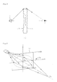
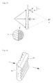
- a rear projection display as, shown in Fig. 15, comprises a projection tube 1 for projecting optical images, a projection lens 2 for enlarging the optical images projected from the projection tube 1, and a rear projection screen 3 for forming images of the enlarged optical images, and an observer P observes the enlarged optical images projected from the projection tube 1 behind the screen 3 to the screen 3.
- a two-panel type screen comprised of a Fresnel lens sheet 4 for converging luminous flux projected from the projection tube 1 to the direction of the observer P and a lenticular lens sheet 5 which disperses the light emitted from the Fresnel lens sheet 4 to the horizontal direction of the screen (screen width direction) and the height direction of the screen (screen height direction) at prescribed angles at an appropriate rate for spreading a viewing angle to a prescribed range.
- the drop of peripheral luminance is an even more serious problem since the quantity of the diffuser, which is mixed in the component materials of the screen 3 for adjusting the dispersiblity of the light emitted from the screen 3, is decreased.
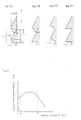
- the lenticular lens 7 for vertical diffusion is disposed on the opposite side of the Fresnel lens 8 of the Fresnel lens sheet 4 by vertically disposing many unit lenses, which are micro-cylindrical lenses 7u arranged with their longitudinal direction in the horizontal direction, as shown in Fig. 16 (e.g. Japanese Patent Application Laid-Open No. 2 - 18540).
- Another method known is increasing the vertical diffusibility of the light of a vertical lenticular lens at the peripheral area more than at the center area of the screen as shown in Fig. 17, so that a drop of the luminance at the peripheral area can be controlled (e.g. Japanese Patent Application Laid-Open No. 7-134338).
- Another method is directing the light in the vertical direction to the direction of the observer by combining two linear Fresnel-lenticular lenses (two linear Fresnel lenses which also serve as lenticular lenses) 9a and 9b to improve the luminosity at the peripheral area of the screen as shown in Fig. 18 (USP No. 4531812).
- Another method is combining two linear Fresnel lenses, one for the vertical direction and the other for the horizontal direction, to deflect the image light to the vertical direction (USP No. 5477380).
- Another method is using a Fresnel lens sheet where a Fresnel lens is disposed on the incident surface of the light from the projection tube and a linear prism for deflecting light in the vertical direction is disposed on the outgoing surface (USP No. 4512631).
- both luminosity on the peripheral area of the screen and luminosity on the entire screen can be implemented which is unlike the case of using a vertical lenticular lens where the vertical diffusion of light is uniform, but even in this case at the peripheral area of the screen light L o which diffuses not only to the direction of the observer P but also to the invalid area at the top and bottom of the screen, as shown in Fig.17, makes it impossible to improve light utilization efficiency.
- US 4 919 518A discloses a multi-screen projector composed of a plurality of unit module projectors, wherein each unit module projector includes a Fresnel lens sheet, lenticular lens sheet and prism sheet interposed therebetween.
- the inventors discovered that the peripheral luminance of a screen can be improved without degrading light utilization efficiency by disposing the linear prism for controlling light in the vertical direction at the light incident side of the Fresnel lens sheet and converging the light emitted from the corners of the Fresnel lens sheet to the direction of the observer since the peripheral luminance ratio of the screen is dominated by the vertical diffusion characteristic of light, and completed the present invention.
- the present invention provides an embodiment where the cross-sectional shape of the unit prism composing the linear prism is comprised of a straight line part and a curved part in the screen height direction, and 0.1 ⁇ r / p ⁇ 4 (where p ⁇ 0.05) and h ⁇ 0.005 are satisfied when the pitch of the unit prism is p (mm), the radius when the shape of the curved part is approximated with a circle is r (mm), and the height of the prism is h (mm).
- the present invention also provides an embodiment where the prism angle of the linear prism is 0° at the screen center area and 3° - 15° at a 90% or outer position from the screen center in the screen height direction.
- the present invention provides an embodiment where the lenticular lens sheet is a double sided lenticular lens sheet which has a lenticular lens on the incident side surface and the outgoing side surface of the image lights, and the top of the lenticular lens on the outgoing side surface is formed roughly at a focussing position on the lenticular lens of the incident side surface.
- a linear prism which acts as a linear Fresnel lens is formed on the surface at the projection light source side of the Fresnel lens sheet. While a lenticular lens for vertical diffusion which is used for a conventional rear projection screen attempts to improve the peripheral luminance of the screen utilizing the dispersibility of light, this linear prism, which can deflect light emitted from the screen to the direction of the observer, can efficiently improve peripheral luminance in the screen height direction.
- a circular Fresnel lens is formed on the surface at the projection light source side of the Fresnel lens sheet, light that enters the rise surface of the circular Fresnel lens does not transmit through the screen, which degrades light utilization efficiency, but according to the present invention, where the circular Fresnel lens is formed on the surface at the observer side of the Fresnel lens sheet, the loss of incident light can be decreased.
- the cross-sectional shape of the unit prism composing the linear prism is comprised of a straight line part and curved part in the screen height direction (that is, a shape where the top of the prism is rounded), light that enters from the curved part to the prism is diffused, therefore a ghost that is generated when the prism angle is at a specified angle cannot occur. This means that a bright screen can be observed even if the screen is observed from a deep angle.
- the prism angle of the linear prism is 0° at the screen center area and 3° - 15° at a 90% or outer position from the screen center in the screen height direction, then loss of light on the linear prism at the projection source side and on the circular Fresnel lens at the observer side is decreased, and the light transmittance of the sheet, which is comprised of the linear prism and the circular Fresnel lens, can be increased.
- Fig. 1 is an external view of a rear projection screen 10 incorporating a prism in accordance with the present invention
- Fig. 2 is an external view of a Fresnel lens sheet incorporating a prism 11 used for this screen 10.
- This screen 10 is used for a projection optical system where projection light from the projection tube enters perpendicularly from the rear face of the screen 10 to the screen 10, just like a conventional rear type projection screen shown in Fig. 15.
- this screen 10 comprises a Fresnel lens sheet incorporating a prism 11 and a lenticular lens sheet 12.
- the Fresnel lens sheet incorporating a prism 11 has a linear prism 13 at the projection light source side, where a plurality of unit prisms 13u, which height in horizontal direction x of the screen is fixed and height in screen height direction y is different, are disposed in screen height direction y.
- the Fresnel lens sheet incorporating a prism 11 also has a circular Fresnel lens 14 at the observer side.
- the linear prism 13 is formed on the projection light source side of the Fresnel lens sheet 11 in this way, it is possible to make the prism angle of the unit prisms 13u different at the up and down in the screen height direction y of the Fresnel lens sheet 11, and to make the orientation of the prism to be symmetrical at the top and bottom in the screen height direction y, as shown in Fig. 2.
- This makes it possible to deflect light emitted from the Fresnel lens sheet 11 more as approaching the top and bottom corners of the Fresnel lens sheet 11, and to direct light emitted from the peripheral area of the Fresnel lens sheet 11 to the observer P without degrading light utilization efficiency, as shown in Fig. 3.
- the converging function of the linear prism 13 is the same as the converging function of the linear Fresnel lens which converges image lights in screen height direction y, but in the case of a linear Fresnel lens, which basically converges lights by itself, the refractive angle is large, but the major difference of the present invention is that the refractive angle can be decreased and reflection loss is made small because a linear prism 13 and the circular Fresnel lens 14 are combined.
- the circular Fresnel lens 14 on the surface at the observer side of the Fresnel lens sheet 11 converges light emitted from the projection tube 1 to a prescribed converging position.
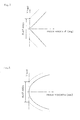
- the converging distance D v in the screen height direction y it is preferable to make the converging distance D h in the horizontal direction x of the screen in a 10% or outer area from the center area 10 0 of the screen 10 in screen height direction y, so that uniformity of luminosity on the screen 10 can be better.
- the focal length f (mm) of the circular Fresnel lens 14, which defines the converging distance D h in horizontal direction x of the screen 10 is set to satisfy 0.8 ⁇ f / D a ⁇ 1.0 , where D a (mm) is the distance from the projection light source 1 to the Fresnel lens sheet 11, in order to improve the luminous uniformity on the entire screen 10.
- Fig. 5A is a cross-sectional view of the preferable shape of the unit prism 13u of the linear prism 13.
- the cross-sectional shape of the unit prism 13u may be a triangle as shown in Fig. 5B, but it is preferable to be a shape comprised of a straight line part to form the prism surface 13a and the curved part 13b approximated by an arc as shown in Fig. 5A.
- the cross-sectional shape may be such that the rise surface 13c of the prism presents a concave lens shape as shown in Fig. 5C. This can also cancel the ghost.
- the rise surface 13c of the prism may have micro-bumps as shown in Fig. 5D. This can also cancel the ghost.
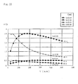
- prism angle ⁇ (deg) of the linear prism 13 it is also preferable to make prism angle ⁇ (deg) of the linear prism 13 to be 0° at the screen center area, and to be 3° - 15° at a 90% or outer position from the screen center in the screen height direction. This can increase light transmittance T(%) at the screen corners of the Fresnel lens sheet incorporating a prism 11 when the converging distance of the Fresnel lens sheet incorporating a prism 11 is constant and can decrease the loss of light, as shown in Fig. 6.
- the relational diagram of prism angle ⁇ (deg) and light transmittance T(%) in Fig. 6 can be determined by calculating reflectance on the circular Fresnel lens 14 surface and the linear prism 13 surface.
- the example shown in Fig. 6 has been calculated for the case when the circular Fresnel lens 14 and the linear prism 13 are combined such that the converging distance of the screen becomes constant.
- the prism angle ⁇ (deg) or the height h (mm) of the unit prism 13u different between the screen center area and the top and bottom edges of the screen
- the prism angle ⁇ (deg) or the height h (mm) continuously change with respect to the distance Y (mm) from the screen center in the screen height direction, as shown in Fig. 7 or Fig. 8.
- a flat area where the unit prisms are not formed may be disposed at the screen center area.
- the prism angle ⁇ (deg) can be determined from the following formula (Formula 2).
- ⁇ arcTAN d H / d Y
- C, K, D, E, F and G are the shape factors of the change of the height of the prism respectively
- Y (mm) is a distance from the center of the screen 10
- H (mm) is the height of the prism.
- the lenticular lens sheet 12 composing the rear projection screen incorporating a prism 10 of the present invention it is preferable to use a double sided lenticular lens sheet where an incident side lenticular lens 12i is on the light source side surface of the image light, an outgoing side lenticular lens 12o is on the observer side surface, and the top of the outgoing side lenticular lens 12o is formed roughly at the focussing position of the incident side lenticular lens 12i, as shown in Fig. 1. It is also preferable to form a light absorption layer 15 at the non-converging area of the incident side lenticular lens 12i on the outgoing side lenticular lens 12o.
- Table 1 shows the shape factors when the shape of the Fresnel lens sheets of these screens are represented with the above mentioned (Formula 1).
- a lenticular lens sheet of these screens we used a double sided lenticular lens sheet having black stripes (a light absorption layer) of 0.72 mm pitch.
- Table 1 shows the result.
- Example 1 K -4.5E-1 -1.03 D 0 0 Incorporat E 0 0 ing linear F 0 0 prism G 0 0 Working C 4.0E-4 2.4E-3 53 3.2 7.3 25.1 852
- Example 2 K -4.5E-1 -1.07 D 0 0 Incorporat E 0 0 ing linear F 0 0 prism G 0 0 Working C 4.0E-4 2.5E-3 12.5 2.5 7.3 22.9 775
- Example 3 K -4.5E-1 -1.03 D 0 0 Incorporat E 0 0 ing
- the present invention it is possible to increase the peak screen gain and to improve the peripheral luminance ratio when an observer views the screen, without degrading light utilization efficiency.
Claims (7)
- Rückprojektionsschirm (10), geeignet zur Verwendung in dem optischen Projektionssystem, wobei Bildlicht, das durch das System projiziert ist, auf die Schirmseite bzw. -fläche senkrecht zu der Schirmseite bzw. -fläche eintritt,
wobei der Schirm (10) ein Fresnel-Linsenblatt (11) und ein linsenförmiges Linsenblatt (12) umfaßt und das Fresnel-Linsenblatt (11) ein lineares Prisma (13) an der Fläche bzw. Oberfläche an der Projektions-Lichtquellenseite (1) aufweist und eine kreisförmige Fresnel-Linse (14) an der Fläche bzw. Oberfläche an der Beobachterseite (8) aufweist, wobei das lineare Prisma (13) adaptiert ist, um als eine lineare Fresnel-Linse zum Konvergieren bzw. Bündeln des projizierten Bildlichts in der ersten Schirmrichtung (y) zu wirken, wobei die Fresnel-Linse (14) adaptiert ist, um weiter das Bildlicht, das von dem linearen Prisma (13) emittiert ist, zu der Schirmzentrumsrichtung zu konvergieren, und wobei das linsenförmige Linsenblatt (12) adaptiert ist, um Bildlicht, das von dem Fresnel-Linsenblatt (11) in der zweiten Schirmrichtung (x) normal auf die erste Schirmrichtung (y) emittiert ist, zu dispergieren bzw. aufzuweiten, und
wobei das lineare Prisma eine Mehrzahl von Einheitsprismen (13u) umfaßt, wobei jedes Einheitsprisma (13u) einen Prismenwinkel (θ) und eine Prismenhöhe (h) aufweist, wobei der Winkel (θ) zwischen der Einheitsprismenseite bzw. -fläche und einer Linie parallel zu der ersten Schirmrichtung (y) definiert ist, wobei die Höhe (h) als senkrecht zu der ersten Schirmrichtung (y) gemessen definiert ist;
dadurch gekennzeichnet, daß die Höhe (h) der Einheitsprismen (13u) kontinuierlich in bezug auf den Abstand (Y) von dem Schirmzentrum in der ersten Schirmrichtung (y) zunimmt, um das periphere Luminanzverhältnis bzw. Umfangs-Helligkeitsverhältnis des Schirms zu verbessern. - Rückprojektionsschirm (10) nach Anspruch 1, wobei der konvergierende Abstand (Dv) in der ersten Schirmrichtung kürzer als der konvergierende Abstand (Dh) in der zweiten Schirmrichtung (x) des Schirms (10) in dem Bereich außerhalb einer 10 % Grenzlinie ist, wobei die 10 % Grenzlinie von dem Mittelpunkt (10o) des Schirms an einem 10 % Abstand eines Abstands zwischen dem Mittelpunkt (10o) und der Schirmkante in der ersten Schirmrichtung (y) positioniert ist.
- Rückprojektionsschirm (10) nach Anspruch 1 oder 2, wobei 0,8 < f/Da < 1,0 erfüllt ist, wenn die Brennweite der kreisförmigen Fresnel-Linse f ist und der Abstand von der Projektionslichtquelle (1) zu dem Fresnel-Linsenblatt (11) Da ist.
- Rückprojektionsschirm (10) nach einem oder mehreren der vorhergehenden Ansprüche, wobei die Querschnittsform eines Einheitsprismas (13u), welches das lineare Prisma (13) zusammensetzt bzw. darstellt, einen Teil (13a) einer geraden Linie und einen gekrümmten Teil (13b) in der ersten Schirmrichtung (y) aufweist, und 0,1 ≤ r/p ≤ 4, wo p ≥ 0,05 mm und h ≥ 0,005 mm erfüllt sind, wenn der Abstand bzw. die Teilung des Einheitsprismas (13u) p ist, ausgedrückt in mm, der Radius, wenn die Form des gekrümmten Teils (13b) mit dem Kreis angenähert ist, r ist, ausgedrückt in mm, und die Höhe des Prismas h ist, ausgedrückt in mm.
- Rückprojektionsschirm (10) nach einem oder mehreren der vorhergehenden Ansprüche, wobei der Prismenwinkel (θ) des linearen Prismas (13) 0° im Schirmzentrumsbereich und 3° - 15° in dem Bereich außerhalb einer 90 % Grenzlinie ist, wo eine 90 % Grenzlinie von dem Mittelpunkt (100) in einem 90 % Abstand eines Abstands zwischen dem Mittelpunkt (100) und der Schirmkante in der ersten Schirmrichtung (y) positioniert ist.
- Rückprojektionsschirm (10) nach einem oder mehreren der vorhergehenden Ansprüche, wobei das linsenförmige Linsenblatt (12) ein doppelseitiges linsenförmiges Linsenblatt ist, welches eine linsenförmige Linse (12i) auf der Einfallsseiten-Fläche bzw. Oberfläche und eine linsenförmige Linse (120) an der Austrittsseiten-Fläche bzw. Oberfläche des projizierten Lichts aufweist, und der Scheitel der linsenförmigen Linse (120) an der Austrittsseiten-Fläche bzw. Oberfläche grob an einem Brennpunkt der linsenförmigen Linse (12i) auf der Einfallsseiten-Fläche bzw. Oberfläche ausgebildet ist.
- Rückprojektionsschirm (10) nach einem oder mehreren der vorhergehenden Ansprüche, wobei ein ebener bzw. flacher Bereich, wo keine Einheitsprismen (13u) ausgebildet sind, an dem Schirmzentrumsbereich angeordnet ist.
Applications Claiming Priority (2)
| Application Number | Priority Date | Filing Date | Title |
|---|---|---|---|
| JP34600797 | 1997-12-16 | ||
| JP34600797 | 1997-12-16 |
Publications (3)
| Publication Number | Publication Date |
|---|---|
| EP0924557A2 EP0924557A2 (de) | 1999-06-23 |
| EP0924557A3 EP0924557A3 (de) | 2000-02-02 |
| EP0924557B1 true EP0924557B1 (de) | 2007-04-18 |
Family
ID=18380506
Family Applications (1)
| Application Number | Title | Priority Date | Filing Date |
|---|---|---|---|
| EP98123503A Expired - Lifetime EP0924557B1 (de) | 1997-12-16 | 1998-12-15 | Rückprojektionsschirm mit einem Prisma |
Country Status (3)
| Country | Link |
|---|---|
| US (1) | US6292295B1 (de) |
| EP (1) | EP0924557B1 (de) |
| DE (1) | DE69837591T2 (de) |
Families Citing this family (19)
| Publication number | Priority date | Publication date | Assignee | Title |
|---|---|---|---|---|
| KR100343964B1 (ko) * | 1999-08-31 | 2002-07-22 | 엘지전자주식회사 | 후면 투사형 표시 장치의 투사 스크린 |
| JP2002090889A (ja) | 2000-09-14 | 2002-03-27 | Kuraray Co Ltd | 背面投射型スクリーン及びその製造方法 |
| KR100396556B1 (ko) * | 2001-10-09 | 2003-09-02 | 삼성전자주식회사 | 프로젝션 텔레비전 스크린 |
| JP2004077535A (ja) * | 2002-08-09 | 2004-03-11 | Dainippon Printing Co Ltd | フレネルレンズシート |
| JP2004170862A (ja) * | 2002-11-22 | 2004-06-17 | Dainippon Printing Co Ltd | フレネルレンズ |
| TWI256520B (en) * | 2003-02-04 | 2006-06-11 | Kuraray Co | Transmission type screen and rear projection type display apparatus |
| US7095558B2 (en) * | 2003-09-01 | 2006-08-22 | Hitachi, Ltd. | Image display device, rear projection type screen used in image display device, Fresnel lens sheet, and method of making Fresnel lens sheet |
| TWI240829B (en) * | 2003-12-12 | 2005-10-01 | Ind Tech Res Inst | Light-guide type diffusive uniform light device |
| JP4701640B2 (ja) * | 2004-02-09 | 2011-06-15 | 株式会社日立製作所 | スクリーン及びそれに用いられるフレネルレンズシート、並びにそれを用いた画像表示装置 |
| JP4581491B2 (ja) * | 2004-06-04 | 2010-11-17 | 株式会社日立製作所 | スクリーン及びそれに用いられるフレネルレンズシート、並びにそれを用いた画像表示装置 |
| JP5055765B2 (ja) * | 2005-12-22 | 2012-10-24 | 株式会社日立製作所 | 画像表示装置、及び、それに用いるフレネルレンズシート並びにスクリーン |
| JP2007286183A (ja) * | 2006-04-13 | 2007-11-01 | Sony Corp | フレネルレンズ、プリズムアレイ、背面投射型表示装置及び照明装置 |
| DE102008020171B4 (de) * | 2008-04-22 | 2010-08-05 | Trw Automotive Electronics & Components Gmbh | Optische Sensorvorrichtung |
| US8042949B2 (en) | 2008-05-02 | 2011-10-25 | Microsoft Corporation | Projection of images onto tangible user interfaces |
| US8068187B2 (en) * | 2008-06-18 | 2011-11-29 | 3M Innovative Properties Company | Stereoscopic 3D liquid crystal display apparatus having a double sided prism film comprising cylindrical lenses and non-contiguous prisms |
| EP2287641B1 (de) * | 2009-08-21 | 2013-07-24 | Mass Technology (H.K.) Ltd. | Fresnellinsenfolie und Leuchte damit |
| EP2752688A1 (de) * | 2013-01-04 | 2014-07-09 | Samsung Electronics Co., Ltd | Fresnellinse und Pyroelektrizitäts-Sensormodul damit |
| USD735400S1 (en) * | 2013-02-09 | 2015-07-28 | SVV Technology Innovations, Inc | Optical lens array lightguide plate |
| CN109634046B (zh) * | 2018-12-24 | 2024-03-19 | 宁波激智科技股份有限公司 | 一种光学屏幕及其制备方法 |
Family Cites Families (13)
| Publication number | Priority date | Publication date | Assignee | Title |
|---|---|---|---|---|
| US3972596A (en) | 1972-05-12 | 1976-08-03 | Donnelly Mirrors, Inc. | View expanding and directing optical system |
| JPS58153924A (ja) * | 1982-03-10 | 1983-09-13 | Hitachi Ltd | 投写用スクリン |
| US4512631A (en) * | 1983-04-21 | 1985-04-23 | Rca Corporation | Rear projection television screen incorporating a prism lens |
| JPS60213534A (ja) * | 1984-04-06 | 1985-10-25 | Makoto Okamura | 監視装置 |
| JPH0623817B2 (ja) * | 1985-07-18 | 1994-03-30 | 旭光学工業株式会社 | 液晶投写型画像表示装置 |
| US4871233A (en) * | 1987-05-12 | 1989-10-03 | Sheiman David M | Thin plate prism and stereoscopic system |
| JPH0830848B2 (ja) * | 1988-04-15 | 1996-03-27 | 株式会社日立製作所 | マルチスクリーンプロジェクタ |
| JP2972271B2 (ja) | 1989-04-26 | 1999-11-08 | 株式会社日立製作所 | 透過型スクリーン及びそれに用いられるシート状部材の製造方法、並びにそのスクリーンを用いた背面投写型画像ディスプレイ装置 |
| EP0447600B1 (de) * | 1990-03-23 | 1995-10-11 | Zeni Lite Buoy Co., Ltd. | Zylinderförmige Linse und dazugehöriges Herstellungsverfahren |
| JP2911627B2 (ja) * | 1991-03-27 | 1999-06-23 | 株式会社日立製作所 | 大画面投写形ディスプレイ |
| US5317349A (en) * | 1993-06-29 | 1994-05-31 | Minnesota Mining And Manufacturing Company | Overhead projector with achromatic fresnel lens |
| JP3390790B2 (ja) * | 1993-08-31 | 2003-03-31 | 大日本印刷株式会社 | プロジェクションスクリーン |
| JPH08262566A (ja) * | 1994-07-22 | 1996-10-11 | Mitsubishi Electric Corp | 投写型表示装置 |
-
1998
- 1998-12-15 DE DE69837591T patent/DE69837591T2/de not_active Expired - Fee Related
- 1998-12-15 US US09/210,796 patent/US6292295B1/en not_active Expired - Fee Related
- 1998-12-15 EP EP98123503A patent/EP0924557B1/de not_active Expired - Lifetime
Also Published As
| Publication number | Publication date |
|---|---|
| EP0924557A3 (de) | 2000-02-02 |
| DE69837591T2 (de) | 2007-12-27 |
| DE69837591D1 (de) | 2007-05-31 |
| US6292295B1 (en) | 2001-09-18 |
| EP0924557A2 (de) | 1999-06-23 |
Similar Documents
| Publication | Publication Date | Title |
|---|---|---|
| EP0924557B1 (de) | Rückprojektionsschirm mit einem Prisma | |
| US6407860B1 (en) | Fresnel lens sheet | |
| US7253954B2 (en) | Flat valley fresnel lens | |
| US4919518A (en) | Multi-screen projector | |
| US6995907B2 (en) | Diffusion sheet for use in transmission-type screen and transmission-type screen | |
| US20040114230A1 (en) | Rear projection display system | |
| US6502942B2 (en) | Rear projection display apparatus and translucent screen for use therein | |
| US7551352B2 (en) | Image display apparatus, as well as, Fresnel lens sheet and screen to be used therein | |
| US6762883B2 (en) | Lenticular lens sheet and rear projection screen | |
| JPS63132228A (ja) | リアプロジェクションスクリーン | |
| JP3697832B2 (ja) | 背面投射型ディスプレー装置及びスクリーンユニット | |
| JP2695422B2 (ja) | 透過型スクリーン | |
| EP1039337B1 (de) | Rückprojektionsschirm | |
| US6900945B2 (en) | Lenticular lens sheet | |
| JPH11271884A (ja) | プリズム付き背面投射型スクリーン | |
| JP2000137294A (ja) | 視野制御シート、背面投射型スクリーンおよび背面投射型ディスプレイ | |
| JPH02135332A (ja) | 背面投写型プロジェクションテレビのレンチキュラーレンズ | |
| US7061677B2 (en) | Screen for projection display in which the light is uniformly transmitted throughout the screen | |
| JP3712085B2 (ja) | レンチキュラーレンズシート | |
| JPH0345987A (ja) | 背面投射型表示装置 | |
| JPH02153338A (ja) | 背面投射型スクリーン及びそれを用いた背面投射型画像表示装置 | |
| JP2695420B2 (ja) | 透過型スクリーン | |
| KR100437060B1 (ko) | 고휘도단판식액정프로젝터용lcd장치 | |
| JPH02306231A (ja) | 背面透過型スクリーン用レンズシート | |
| JPH0345988A (ja) | 背面投射型表示装置 |
Legal Events
| Date | Code | Title | Description |
|---|---|---|---|
| PUAI | Public reference made under article 153(3) epc to a published international application that has entered the european phase |
Free format text: ORIGINAL CODE: 0009012 |
|
| AK | Designated contracting states |
Kind code of ref document: A2 Designated state(s): DE FR GB NL |
|
| AX | Request for extension of the european patent |
Free format text: AL;LT;LV;MK;RO;SI |
|
| PUAL | Search report despatched |
Free format text: ORIGINAL CODE: 0009013 |
|
| AK | Designated contracting states |
Kind code of ref document: A3 Designated state(s): AT BE CH CY DE DK ES FI FR GB GR IE IT LI LU MC NL PT SE |
|
| AX | Request for extension of the european patent |
Free format text: AL;LT;LV;MK;RO;SI |
|
| 17P | Request for examination filed |
Effective date: 20000731 |
|
| AKX | Designation fees paid |
Free format text: DE FR GB NL |
|
| 17Q | First examination report despatched |
Effective date: 20020403 |
|
| GRAP | Despatch of communication of intention to grant a patent |
Free format text: ORIGINAL CODE: EPIDOSNIGR1 |
|
| GRAS | Grant fee paid |
Free format text: ORIGINAL CODE: EPIDOSNIGR3 |
|
| GRAJ | Information related to disapproval of communication of intention to grant by the applicant or resumption of examination proceedings by the epo deleted |
Free format text: ORIGINAL CODE: EPIDOSDIGR1 |
|
| GRAP | Despatch of communication of intention to grant a patent |
Free format text: ORIGINAL CODE: EPIDOSNIGR1 |
|
| GRAS | Grant fee paid |
Free format text: ORIGINAL CODE: EPIDOSNIGR3 |
|
| GRAA | (expected) grant |
Free format text: ORIGINAL CODE: 0009210 |
|
| AK | Designated contracting states |
Kind code of ref document: B1 Designated state(s): DE FR GB NL |
|
| REF | Corresponds to: |
Ref document number: 69837591 Country of ref document: DE Date of ref document: 20070531 Kind code of ref document: P |
|
| ET | Fr: translation filed | ||
| NLV1 | Nl: lapsed or annulled due to failure to fulfill the requirements of art. 29p and 29m of the patents act | ||
| PG25 | Lapsed in a contracting state [announced via postgrant information from national office to epo] |
Ref country code: NL Free format text: LAPSE BECAUSE OF FAILURE TO SUBMIT A TRANSLATION OF THE DESCRIPTION OR TO PAY THE FEE WITHIN THE PRESCRIBED TIME-LIMIT Effective date: 20070418 |
|
| PLBE | No opposition filed within time limit |
Free format text: ORIGINAL CODE: 0009261 |
|
| STAA | Information on the status of an ep patent application or granted ep patent |
Free format text: STATUS: NO OPPOSITION FILED WITHIN TIME LIMIT |
|
| 26N | No opposition filed |
Effective date: 20080121 |
|
| PGFP | Annual fee paid to national office [announced via postgrant information from national office to epo] |
Ref country code: GB Payment date: 20071212 Year of fee payment: 10 Ref country code: FR Payment date: 20071210 Year of fee payment: 10 |
|
| PGFP | Annual fee paid to national office [announced via postgrant information from national office to epo] |
Ref country code: DE Payment date: 20071213 Year of fee payment: 10 |
|
| GBPC | Gb: european patent ceased through non-payment of renewal fee |
Effective date: 20081215 |
|
| REG | Reference to a national code |
Ref country code: FR Ref legal event code: ST Effective date: 20090831 |
|
| PG25 | Lapsed in a contracting state [announced via postgrant information from national office to epo] |
Ref country code: DE Free format text: LAPSE BECAUSE OF NON-PAYMENT OF DUE FEES Effective date: 20090701 |
|
| PG25 | Lapsed in a contracting state [announced via postgrant information from national office to epo] |
Ref country code: GB Free format text: LAPSE BECAUSE OF NON-PAYMENT OF DUE FEES Effective date: 20081215 |
|
| PG25 | Lapsed in a contracting state [announced via postgrant information from national office to epo] |
Ref country code: FR Free format text: LAPSE BECAUSE OF NON-PAYMENT OF DUE FEES Effective date: 20081231 |