EP0924557B1 - Rear projection screen incorporating a prism - Google Patents
Rear projection screen incorporating a prism Download PDFInfo
- Publication number
- EP0924557B1 EP0924557B1 EP98123503A EP98123503A EP0924557B1 EP 0924557 B1 EP0924557 B1 EP 0924557B1 EP 98123503 A EP98123503 A EP 98123503A EP 98123503 A EP98123503 A EP 98123503A EP 0924557 B1 EP0924557 B1 EP 0924557B1
- Authority
- EP
- European Patent Office
- Prior art keywords
- screen
- prism
- fresnel lens
- lens sheet
- distance
- Prior art date
- Legal status (The legal status is an assumption and is not a legal conclusion. Google has not performed a legal analysis and makes no representation as to the accuracy of the status listed.)
- Expired - Lifetime
Links
Images


Classifications
-
- G—PHYSICS
- G03—PHOTOGRAPHY; CINEMATOGRAPHY; ANALOGOUS TECHNIQUES USING WAVES OTHER THAN OPTICAL WAVES; ELECTROGRAPHY; HOLOGRAPHY
- G03B—APPARATUS OR ARRANGEMENTS FOR TAKING PHOTOGRAPHS OR FOR PROJECTING OR VIEWING THEM; APPARATUS OR ARRANGEMENTS EMPLOYING ANALOGOUS TECHNIQUES USING WAVES OTHER THAN OPTICAL WAVES; ACCESSORIES THEREFOR
- G03B21/00—Projectors or projection-type viewers; Accessories therefor
- G03B21/54—Accessories
- G03B21/56—Projection screens
- G03B21/60—Projection screens characterised by the nature of the surface
- G03B21/62—Translucent screens
- G03B21/625—Lenticular translucent screens
Definitions
- This invention relates to a rear projection screen used for a rear projection display.
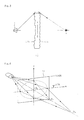
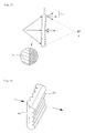
- a rear projection display as, shown in Fig. 15, comprises a projection tube 1 for projecting optical images, a projection lens 2 for enlarging the optical images projected from the projection tube 1, and a rear projection screen 3 for forming images of the enlarged optical images, and an observer P observes the enlarged optical images projected from the projection tube 1 behind the screen 3 to the screen 3.
- a two-panel type screen comprised of a Fresnel lens sheet 4 for converging luminous flux projected from the projection tube 1 to the direction of the observer P and a lenticular lens sheet 5 which disperses the light emitted from the Fresnel lens sheet 4 to the horizontal direction of the screen (screen width direction) and the height direction of the screen (screen height direction) at prescribed angles at an appropriate rate for spreading a viewing angle to a prescribed range.
- the drop of peripheral luminance is an even more serious problem since the quantity of the diffuser, which is mixed in the component materials of the screen 3 for adjusting the dispersiblity of the light emitted from the screen 3, is decreased.
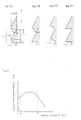
- the lenticular lens 7 for vertical diffusion is disposed on the opposite side of the Fresnel lens 8 of the Fresnel lens sheet 4 by vertically disposing many unit lenses, which are micro-cylindrical lenses 7u arranged with their longitudinal direction in the horizontal direction, as shown in Fig. 16 (e.g. Japanese Patent Application Laid-Open No. 2 - 18540).
- Another method known is increasing the vertical diffusibility of the light of a vertical lenticular lens at the peripheral area more than at the center area of the screen as shown in Fig. 17, so that a drop of the luminance at the peripheral area can be controlled (e.g. Japanese Patent Application Laid-Open No. 7-134338).
- Another method is directing the light in the vertical direction to the direction of the observer by combining two linear Fresnel-lenticular lenses (two linear Fresnel lenses which also serve as lenticular lenses) 9a and 9b to improve the luminosity at the peripheral area of the screen as shown in Fig. 18 (USP No. 4531812).
- Another method is combining two linear Fresnel lenses, one for the vertical direction and the other for the horizontal direction, to deflect the image light to the vertical direction (USP No. 5477380).
- Another method is using a Fresnel lens sheet where a Fresnel lens is disposed on the incident surface of the light from the projection tube and a linear prism for deflecting light in the vertical direction is disposed on the outgoing surface (USP No. 4512631).
- both luminosity on the peripheral area of the screen and luminosity on the entire screen can be implemented which is unlike the case of using a vertical lenticular lens where the vertical diffusion of light is uniform, but even in this case at the peripheral area of the screen light L o which diffuses not only to the direction of the observer P but also to the invalid area at the top and bottom of the screen, as shown in Fig.17, makes it impossible to improve light utilization efficiency.
- US 4 919 518A discloses a multi-screen projector composed of a plurality of unit module projectors, wherein each unit module projector includes a Fresnel lens sheet, lenticular lens sheet and prism sheet interposed therebetween.
- the inventors discovered that the peripheral luminance of a screen can be improved without degrading light utilization efficiency by disposing the linear prism for controlling light in the vertical direction at the light incident side of the Fresnel lens sheet and converging the light emitted from the corners of the Fresnel lens sheet to the direction of the observer since the peripheral luminance ratio of the screen is dominated by the vertical diffusion characteristic of light, and completed the present invention.
- the present invention provides an embodiment where the cross-sectional shape of the unit prism composing the linear prism is comprised of a straight line part and a curved part in the screen height direction, and 0.1 ⁇ r / p ⁇ 4 (where p ⁇ 0.05) and h ⁇ 0.005 are satisfied when the pitch of the unit prism is p (mm), the radius when the shape of the curved part is approximated with a circle is r (mm), and the height of the prism is h (mm).
- the present invention also provides an embodiment where the prism angle of the linear prism is 0° at the screen center area and 3° - 15° at a 90% or outer position from the screen center in the screen height direction.
- the present invention provides an embodiment where the lenticular lens sheet is a double sided lenticular lens sheet which has a lenticular lens on the incident side surface and the outgoing side surface of the image lights, and the top of the lenticular lens on the outgoing side surface is formed roughly at a focussing position on the lenticular lens of the incident side surface.
- a linear prism which acts as a linear Fresnel lens is formed on the surface at the projection light source side of the Fresnel lens sheet. While a lenticular lens for vertical diffusion which is used for a conventional rear projection screen attempts to improve the peripheral luminance of the screen utilizing the dispersibility of light, this linear prism, which can deflect light emitted from the screen to the direction of the observer, can efficiently improve peripheral luminance in the screen height direction.
- a circular Fresnel lens is formed on the surface at the projection light source side of the Fresnel lens sheet, light that enters the rise surface of the circular Fresnel lens does not transmit through the screen, which degrades light utilization efficiency, but according to the present invention, where the circular Fresnel lens is formed on the surface at the observer side of the Fresnel lens sheet, the loss of incident light can be decreased.
- the cross-sectional shape of the unit prism composing the linear prism is comprised of a straight line part and curved part in the screen height direction (that is, a shape where the top of the prism is rounded), light that enters from the curved part to the prism is diffused, therefore a ghost that is generated when the prism angle is at a specified angle cannot occur. This means that a bright screen can be observed even if the screen is observed from a deep angle.
- the prism angle of the linear prism is 0° at the screen center area and 3° - 15° at a 90% or outer position from the screen center in the screen height direction, then loss of light on the linear prism at the projection source side and on the circular Fresnel lens at the observer side is decreased, and the light transmittance of the sheet, which is comprised of the linear prism and the circular Fresnel lens, can be increased.
- Fig. 1 is an external view of a rear projection screen 10 incorporating a prism in accordance with the present invention
- Fig. 2 is an external view of a Fresnel lens sheet incorporating a prism 11 used for this screen 10.
- This screen 10 is used for a projection optical system where projection light from the projection tube enters perpendicularly from the rear face of the screen 10 to the screen 10, just like a conventional rear type projection screen shown in Fig. 15.
- this screen 10 comprises a Fresnel lens sheet incorporating a prism 11 and a lenticular lens sheet 12.
- the Fresnel lens sheet incorporating a prism 11 has a linear prism 13 at the projection light source side, where a plurality of unit prisms 13u, which height in horizontal direction x of the screen is fixed and height in screen height direction y is different, are disposed in screen height direction y.
- the Fresnel lens sheet incorporating a prism 11 also has a circular Fresnel lens 14 at the observer side.
- the linear prism 13 is formed on the projection light source side of the Fresnel lens sheet 11 in this way, it is possible to make the prism angle of the unit prisms 13u different at the up and down in the screen height direction y of the Fresnel lens sheet 11, and to make the orientation of the prism to be symmetrical at the top and bottom in the screen height direction y, as shown in Fig. 2.
- This makes it possible to deflect light emitted from the Fresnel lens sheet 11 more as approaching the top and bottom corners of the Fresnel lens sheet 11, and to direct light emitted from the peripheral area of the Fresnel lens sheet 11 to the observer P without degrading light utilization efficiency, as shown in Fig. 3.
- the converging function of the linear prism 13 is the same as the converging function of the linear Fresnel lens which converges image lights in screen height direction y, but in the case of a linear Fresnel lens, which basically converges lights by itself, the refractive angle is large, but the major difference of the present invention is that the refractive angle can be decreased and reflection loss is made small because a linear prism 13 and the circular Fresnel lens 14 are combined.
- the circular Fresnel lens 14 on the surface at the observer side of the Fresnel lens sheet 11 converges light emitted from the projection tube 1 to a prescribed converging position.
- the converging distance D v in the screen height direction y it is preferable to make the converging distance D h in the horizontal direction x of the screen in a 10% or outer area from the center area 10 0 of the screen 10 in screen height direction y, so that uniformity of luminosity on the screen 10 can be better.
- the focal length f (mm) of the circular Fresnel lens 14, which defines the converging distance D h in horizontal direction x of the screen 10 is set to satisfy 0.8 ⁇ f / D a ⁇ 1.0 , where D a (mm) is the distance from the projection light source 1 to the Fresnel lens sheet 11, in order to improve the luminous uniformity on the entire screen 10.
- Fig. 5A is a cross-sectional view of the preferable shape of the unit prism 13u of the linear prism 13.
- the cross-sectional shape of the unit prism 13u may be a triangle as shown in Fig. 5B, but it is preferable to be a shape comprised of a straight line part to form the prism surface 13a and the curved part 13b approximated by an arc as shown in Fig. 5A.
- the cross-sectional shape may be such that the rise surface 13c of the prism presents a concave lens shape as shown in Fig. 5C. This can also cancel the ghost.
- the rise surface 13c of the prism may have micro-bumps as shown in Fig. 5D. This can also cancel the ghost.
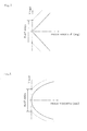
- prism angle ⁇ (deg) of the linear prism 13 it is also preferable to make prism angle ⁇ (deg) of the linear prism 13 to be 0° at the screen center area, and to be 3° - 15° at a 90% or outer position from the screen center in the screen height direction. This can increase light transmittance T(%) at the screen corners of the Fresnel lens sheet incorporating a prism 11 when the converging distance of the Fresnel lens sheet incorporating a prism 11 is constant and can decrease the loss of light, as shown in Fig. 6.
- the relational diagram of prism angle ⁇ (deg) and light transmittance T(%) in Fig. 6 can be determined by calculating reflectance on the circular Fresnel lens 14 surface and the linear prism 13 surface.
- the example shown in Fig. 6 has been calculated for the case when the circular Fresnel lens 14 and the linear prism 13 are combined such that the converging distance of the screen becomes constant.
- the prism angle ⁇ (deg) or the height h (mm) of the unit prism 13u different between the screen center area and the top and bottom edges of the screen
- the prism angle ⁇ (deg) or the height h (mm) continuously change with respect to the distance Y (mm) from the screen center in the screen height direction, as shown in Fig. 7 or Fig. 8.
- a flat area where the unit prisms are not formed may be disposed at the screen center area.
- the prism angle ⁇ (deg) can be determined from the following formula (Formula 2).
- ⁇ arcTAN d H / d Y
- C, K, D, E, F and G are the shape factors of the change of the height of the prism respectively
- Y (mm) is a distance from the center of the screen 10
- H (mm) is the height of the prism.
- the lenticular lens sheet 12 composing the rear projection screen incorporating a prism 10 of the present invention it is preferable to use a double sided lenticular lens sheet where an incident side lenticular lens 12i is on the light source side surface of the image light, an outgoing side lenticular lens 12o is on the observer side surface, and the top of the outgoing side lenticular lens 12o is formed roughly at the focussing position of the incident side lenticular lens 12i, as shown in Fig. 1. It is also preferable to form a light absorption layer 15 at the non-converging area of the incident side lenticular lens 12i on the outgoing side lenticular lens 12o.
- Table 1 shows the shape factors when the shape of the Fresnel lens sheets of these screens are represented with the above mentioned (Formula 1).
- a lenticular lens sheet of these screens we used a double sided lenticular lens sheet having black stripes (a light absorption layer) of 0.72 mm pitch.
- Table 1 shows the result.
- Example 1 K -4.5E-1 -1.03 D 0 0 Incorporat E 0 0 ing linear F 0 0 prism G 0 0 Working C 4.0E-4 2.4E-3 53 3.2 7.3 25.1 852
- Example 2 K -4.5E-1 -1.07 D 0 0 Incorporat E 0 0 ing linear F 0 0 prism G 0 0 Working C 4.0E-4 2.5E-3 12.5 2.5 7.3 22.9 775
- Example 3 K -4.5E-1 -1.03 D 0 0 Incorporat E 0 0 ing
- the present invention it is possible to increase the peak screen gain and to improve the peripheral luminance ratio when an observer views the screen, without degrading light utilization efficiency.
Landscapes
- Physics & Mathematics (AREA)
- General Physics & Mathematics (AREA)
- Overhead Projectors And Projection Screens (AREA)
- Projection Apparatus (AREA)
Description
- This invention relates to a rear projection screen used for a rear projection display.
- A rear projection display as, shown in Fig. 15, comprises a
projection tube 1 for projecting optical images, aprojection lens 2 for enlarging the optical images projected from theprojection tube 1, and arear projection screen 3 for forming images of the enlarged optical images, and an observer P observes the enlarged optical images projected from theprojection tube 1 behind thescreen 3 to thescreen 3. - As the
rear projection screen 3, a two-panel type screen comprised of a Fresnellens sheet 4 for converging luminous flux projected from theprojection tube 1 to the direction of the observer P and alenticular lens sheet 5 which disperses the light emitted from the Fresnellens sheet 4 to the horizontal direction of the screen (screen width direction) and the height direction of the screen (screen height direction) at prescribed angles at an appropriate rate for spreading a viewing angle to a prescribed range. - Recently in rear projection displays, decreasing distance between the
projection lens 2 and thescreen 3 is demanded to make the display slimmer. To meet this demand, it is necessary to increase the Fresnel angle of the Fresnellens sheet 4. If this Fresnel angle is increased, however, reflection loss at the peripheral area of the Fresnellens sheet 4 increases and the ratio of luminosity at the corners of thescreen 3 to that at the center area of the screen 3 (so called peripheral luminance ratio) drops, which is a problem. - If the peak screen gain is increased to improve the luminosity of the rear projection display, the drop of peripheral luminance is an even more serious problem since the quantity of the diffuser, which is mixed in the component materials of the
screen 3 for adjusting the dispersiblity of the light emitted from thescreen 3, is decreased. - Conventionally, various countermeasures against such a problem of a peripheral luminance drop have been suggested. For example, the
lenticular lens 7 for vertical diffusion is disposed on the opposite side of the Fresnel lens 8 of the Fresnellens sheet 4 by vertically disposing many unit lenses, which aremicro-cylindrical lenses 7u arranged with their longitudinal direction in the horizontal direction, as shown in Fig. 16 (e.g. Japanese Patent Application Laid-Open No. 2 - 18540). Another method known is increasing the vertical diffusibility of the light of a vertical lenticular lens at the peripheral area more than at the center area of the screen as shown in Fig. 17, so that a drop of the luminance at the peripheral area can be controlled (e.g. Japanese Patent Application Laid-Open No. 7-134338). - Another method is directing the light in the vertical direction to the direction of the observer by combining two linear Fresnel-lenticular lenses (two linear Fresnel lenses which also serve as lenticular lenses) 9a and 9b to improve the luminosity at the peripheral area of the screen as shown in Fig. 18 (USP No. 4531812).
- Another method is combining two linear Fresnel lenses, one for the vertical direction and the other for the horizontal direction, to deflect the image light to the vertical direction (USP No. 5477380).
- Another method is using a Fresnel lens sheet where a Fresnel lens is disposed on the incident surface of the light from the projection tube and a linear prism for deflecting light in the vertical direction is disposed on the outgoing surface (USP No. 4512631).
- With the above mentioned method of using the
lenticular lens 7 for vertical diffusion in Fig. 16. however, when the peak screen gain exceeds 7, color irregularity (color shift) of the screen deteriorates because the refractive index of material differs depending on the difference of color (difference of wavelengths), therefore, reflection loss on the Fresnel lens differs depending on the difference of color, although color irregularity of the screen is not a problem when the peak screen gain is low due to the contribution of diffusion of lights in the vertical direction of thelenticular lens 7 for vertical diffusion. Another problem is that if diffusibility of thelenticular lens 7 for vertical diffusion is increased to increase peripheral luminance, the screen gain at the screen center area drops. - If a vertical lenticular lens is used where the vertical diffusibility of light is higher at the peripheral area than at the screen center area, both luminosity on the peripheral area of the screen and luminosity on the entire screen can be implemented which is unlike the case of using a vertical lenticular lens where the vertical diffusion of light is uniform, but even in this case at the peripheral area of the screen light Lo which diffuses not only to the direction of the observer P but also to the invalid area at the top and bottom of the screen, as shown in Fig.17, makes it impossible to improve light utilization efficiency.
- In the case of a method in Fig. 18, where two linear Fresnel-
lenticular lenses 9a and 9b are combined, loss of light due to reflection is greater than the case of using a circular Fresnel lens, since the refraction at the linear Fresnel-lenticular lenses 9a and 9b is high. Also in the case of a screen using the linear Fresnel-lenticular lenses 9a and 9b, light utilization efficiency in the effective area of the screen degrades due to the diffusion of light. - Even in the screen where two linear Fresnel lenses, one for the vertical direction and the other for the horizontal direction, are combined to deflect the image light in the vertical direction, the loss of light is greater than the case of using a circular Fresnel lens.
- In the case of a screen using a Fresnel lens sheet where a Fresnel lens is on the incident surface of light from the projection tube and a linear prism for deflecting light in the vertical direction is on the outgoing surface, disposing the Fresnel lens on the incident surface of the light from the projection tube increases the loss of lights.
- US 4 919 518A discloses a multi-screen projector composed of a plurality of unit module projectors, wherein each unit module projector includes a Fresnel lens sheet, lenticular lens sheet and prism sheet interposed therebetween.
- Accordingly, it is an object of the present invention to solve the above problems of prior art, to increase the peak screen gain, and to improve the peripheral luminance ratio, without degrading light utilization efficiency.
- The inventors discovered that the peripheral luminance of a screen can be improved without degrading light utilization efficiency by disposing the linear prism for controlling light in the vertical direction at the light incident side of the Fresnel lens sheet and converging the light emitted from the corners of the Fresnel lens sheet to the direction of the observer since the peripheral luminance ratio of the screen is dominated by the vertical diffusion characteristic of light, and completed the present invention.
- According to the invention there is provided a rear projection screen as defined in
claim 1. Preferred embodiments are defined in the dependent subclaims. - More particularly, on the shape of the linear prism of the rear projection screen, the present invention provides an embodiment where the cross-sectional shape of the unit prism composing the linear prism is comprised of a straight line part and a curved part in the screen height direction, and 0.1 ≦ r / p ≦ 4 (where p ≧ 0.05) and h ≧ 0.005 are satisfied when the pitch of the unit prism is p (mm), the radius when the shape of the curved part is approximated with a circle is r (mm), and the height of the prism is h (mm).
- The present invention also provides an embodiment where the prism angle of the linear prism is 0° at the screen center area and 3° - 15° at a 90% or outer position from the screen center in the screen height direction.
- Also in the above mentioned rear projection screen, the present invention provides an embodiment where the lenticular lens sheet is a double sided lenticular lens sheet which has a lenticular lens on the incident side surface and the outgoing side surface of the image lights, and the top of the lenticular lens on the outgoing side surface is formed roughly at a focussing position on the lenticular lens of the incident side surface.
- According to the rear projection screen of the present invention, a linear prism which acts as a linear Fresnel lens is formed on the surface at the projection light source side of the Fresnel lens sheet. While a lenticular lens for vertical diffusion which is used for a conventional rear projection screen attempts to improve the peripheral luminance of the screen utilizing the dispersibility of light, this linear prism, which can deflect light emitted from the screen to the direction of the observer, can efficiently improve peripheral luminance in the screen height direction.
- If a circular Fresnel lens is formed on the surface at the projection light source side of the Fresnel lens sheet, light that enters the rise surface of the circular Fresnel lens does not transmit through the screen, which degrades light utilization efficiency, but according to the present invention, where the circular Fresnel lens is formed on the surface at the observer side of the Fresnel lens sheet, the loss of incident light can be decreased.
- Preferably regarding the shape of the linear prism of this rear projection screen, if the cross-sectional shape of the unit prism composing the linear prism is comprised of a straight line part and curved part in the screen height direction (that is, a shape where the top of the prism is rounded), light that enters from the curved part to the prism is diffused, therefore a ghost that is generated when the prism angle is at a specified angle cannot occur. This means that a bright screen can be observed even if the screen is observed from a deep angle.
- Preferably, if the prism angle of the linear prism is 0° at the screen center area and 3° - 15° at a 90% or outer position from the screen center in the screen height direction, then loss of light on the linear prism at the projection source side and on the circular Fresnel lens at the observer side is decreased, and the light transmittance of the sheet, which is comprised of the linear prism and the circular Fresnel lens, can be increased.
- Fig. 1 is an external view of the rear projection screen incorporating a prism of the present invention;
- Fig. 2 is an external view of the Fresnel lens sheet incorporating a prism;
- Fig. 3 is an explanatory diagram depicting the lights of the Fresnel lens sheet incorporating a prism;
- Fig. 4 is an explanatory diagram depicting the lights of the rear projection screen incorporating a prism;
- Figs. 5A, 5B, 5C and 5D are cross-sectional views of the unit prism;
- Fig. 6 is a relational diagram of the prism angle and the light transmittance of the Fresnel lens sheet incorporating a prism;
- Fig. 7 is a relational diagram of the prism angle of the unit prism and the distance from the screen center in the screen height direction;
- Fig. 8 is a relational diagram of the height of the lens of the unit prism and the distance from the screen center in the screen height direction;
- Fig. 9 is a relational diagram of the ratio between the distance Da(mm) from the projection light source to the Fresnel lens sheet and the focal length f(mm) of the circular Fresnel lens (f/Da), the distance Da(mm) from the projection light source to the Fresnel lens sheet, and the distance Db(mm) between the converging point and the Fresnel lens sheet;
- Fig. 10 is a relational diagram between the distance Y(mm) from the screen center in the screen height direction and r/p;
- Fig. 11 is a diagram depicting the typical cross-sectional shape of the unit prism;
- Fig. 12 is a diagram depicting the typical cross-sectional shape of the unit prism;
- Fig. 13 is a diagram depicting the typical cross-sectional shape of the unit prism;
- Fig. 14 is a diagram depicting the typical cross-sectional shape of the unit prism;
- Fig. 15 is an explanatory diagram depicting the general lights of the rear projection display;
- Fig. 16 is a cross-sectional view of a conventional Fresnel lens sheet;
- Fig. 17 is a cross-sectional view of a conventional Fresnel lens sheet; and
- Fig. 18 is an external view of a conventional Fresnel lens sheet.
- The present invention will now be described referring to the drawings. In the drawings, same numerals denote a same or similar composing element.
- Fig. 1 is an external view of a
rear projection screen 10 incorporating a prism in accordance with the present invention, and Fig. 2 is an external view of a Fresnel lens sheet incorporating aprism 11 used for thisscreen 10. - This
screen 10 is used for a projection optical system where projection light from the projection tube enters perpendicularly from the rear face of thescreen 10 to thescreen 10, just like a conventional rear type projection screen shown in Fig. 15. - As Fig. 1 shows, this
screen 10 comprises a Fresnel lens sheet incorporating aprism 11 and alenticular lens sheet 12. As Fig. 2 shows, the Fresnel lens sheet incorporating aprism 11 has alinear prism 13 at the projection light source side, where a plurality ofunit prisms 13u, which height in horizontal direction x of the screen is fixed and height in screen height direction y is different, are disposed in screen height direction y. The Fresnel lens sheet incorporating aprism 11 also has a circular Fresnellens 14 at the observer side. - When the
linear prism 13 is formed on the projection light source side of the Fresnellens sheet 11 in this way, it is possible to make the prism angle of theunit prisms 13u different at the up and down in the screen height direction y of the Fresnellens sheet 11, and to make the orientation of the prism to be symmetrical at the top and bottom in the screen height direction y, as shown in Fig. 2. This makes it possible to deflect light emitted from the Fresnellens sheet 11 more as approaching the top and bottom corners of the Fresnellens sheet 11, and to direct light emitted from the peripheral area of the Fresnellens sheet 11 to the observer P without degrading light utilization efficiency, as shown in Fig. 3. - The converging function of the
linear prism 13 is the same as the converging function of the linear Fresnel lens which converges image lights in screen height direction y, but in the case of a linear Fresnel lens, which basically converges lights by itself, the refractive angle is large, but the major difference of the present invention is that the refractive angle can be decreased and reflection loss is made small because alinear prism 13 and the circular Fresnellens 14 are combined. - The circular Fresnel
lens 14 on the surface at the observer side of the Fresnellens sheet 11 converges light emitted from theprojection tube 1 to a prescribed converging position. Thelinear prism 13 on the surface at the projection light source side of theFresnel lens sheet 11, on the other hand, deflects light emitted from theFresnel lens sheet 11 more as approaching the top and bottom corners of theFresnel lens sheet 11, as mentioned above. Therefore in the peripheral area of thisscreen 10, the converging distance Dv in height direction y of thescreen 10 is shorter than the converging distance Dh in horizontal direction x of the screen, as shown in Fig.4. In this case, it is preferable to make the converging distance Dv in the screen height direction y to be shorter than the converging distance Dh in the horizontal direction x of the screen in a 10% or outer area from thecenter area 100 of thescreen 10 in screen height direction y, so that uniformity of luminosity on thescreen 10 can be better. - It is preferable to set the focal length f (mm) of the
circular Fresnel lens 14, which defines the converging distance Dh in horizontal direction x of thescreen 10 to satisfy
where Da (mm) is the distance from theprojection light source 1 to theFresnel lens sheet 11, in order to improve the luminous uniformity on theentire screen 10. - Fig. 5A is a cross-sectional view of the preferable shape of the
unit prism 13u of thelinear prism 13. In accordance with the present invention, the cross-sectional shape of theunit prism 13u may be a triangle as shown in Fig. 5B, but it is preferable to be a shape comprised of a straight line part to form the prism surface 13a and thecurved part 13b approximated by an arc as shown in Fig. 5A. By making the shape of theunit prism 13u like this, light which enters from thecurved part 13b to thelinear prism 13 is diffused, therefore when theunit prism 13u has a cross-sectional shape shown in Fig. 5B, a ghost generated at specific prism angle θ can be canceled. Also even when the observer looks thescreen 10 from a deep angle, thescreen 10 can be observed as bright. - As a shape of the
unit prism 13u, the cross-sectional shape may be such that therise surface 13c of the prism presents a concave lens shape as shown in Fig. 5C. This can also cancel the ghost. - Also as a shape of the
unit prism 13u, therise surface 13c of the prism may have micro-bumps as shown in Fig. 5D. This can also cancel the ghost. - When the radius of an arc that approximates the
curved part 13b is r (mm), and the length of one pitch is p (mm) and the height of the prism is h (mm), it is preferable to be satisfied

unit prism 13u, so that uniformity of luminosity on the entire screen can be maintained when thescreen 10 is observed from a position other than the position of observer P shown in Fig. 3. - It is also preferable to make prism angle θ (deg) of the
linear prism 13 to be 0° at the screen center area, and to be 3° - 15° at a 90% or outer position from the screen center in the screen height direction. This can increase light transmittance T(%) at the screen corners of the Fresnel lens sheet incorporating aprism 11 when the converging distance of the Fresnel lens sheet incorporating aprism 11 is constant and can decrease the loss of light, as shown in Fig. 6. - The relational diagram of prism angle θ (deg) and light transmittance T(%) in Fig. 6 can be determined by calculating reflectance on the
circular Fresnel lens 14 surface and thelinear prism 13 surface. The example shown in Fig. 6 has been calculated for the case when thecircular Fresnel lens 14 and thelinear prism 13 are combined such that the converging distance of the screen becomes constant. - As an aspect to make the prism angle θ (deg) or the height h (mm) of the
unit prism 13u different between the screen center area and the top and bottom edges of the screen, the prism angle θ (deg) or the height h (mm) continuously change with respect to the distance Y (mm) from the screen center in the screen height direction, as shown in Fig. 7 or Fig. 8. As shown with a broken line in these figures, a flat area where the unit prisms are not formed may be disposed at the screen center area. - The shape of the
linear prism 13 which has the above shape can be derived from the following (Formula 1)
- The prism angle θ (deg) can be determined from the following formula (Formula 2).

- In the above (Formula 1) and (Formula 2), C, K, D, E, F and G are the shape factors of the change of the height of the prism respectively, Y (mm) is a distance from the center of the
screen 10, and H (mm)is the height of the prism. - As the
lenticular lens sheet 12 composing the rear projection screen incorporating aprism 10 of the present invention, it is preferable to use a double sided lenticular lens sheet where an incident sidelenticular lens 12i is on the light source side surface of the image light, an outgoing side lenticular lens 12o is on the observer side surface, and the top of the outgoing side lenticular lens 12o is formed roughly at the focussing position of the incident sidelenticular lens 12i, as shown in Fig. 1. It is also preferable to form alight absorption layer 15 at the non-converging area of the incident sidelenticular lens 12i on the outgoing side lenticular lens 12o. - Working Examples of the present invention will now be concretely described below.
- We fabricated 50 inch size rear projection displays using the screen in Fig. 1 (working examples 1-3), the screen in Fig. 15 (comparative example 1) or the screen comprised of a lenticular lens for vertical diffusion in Fig. 17 and a lenticular lens sheet (located on an observer side) (comparative example 2).
- Table 1 shows the shape factors when the shape of the Fresnel lens sheets of these screens are represented with the above mentioned (Formula 1). As a lenticular lens sheet of these screens, we used a double sided lenticular lens sheet having black stripes (a light absorption layer) of 0.72 mm pitch.
- We calculated the converging distance (m) from left to right (horizontal direction) of the screen, the converging distance (m) from top to bottom (height direction) of the screen, and measured the peak screen gain, peripheral luminance ratio (%) and the deviation of CYE color coordinates at the screen corners from the color coordinates at the center area. The distance between the projection tube and the screen is 826 mm for the working examples 1 and 3 and comparison examples 1 and 2, and 866 mm for the working example 2. The measurement position of the above evaluation items is 3 m from the front face of the screen. To adjust the peak screen gain to be constant, a diffuser was dispersed on the sheet for the Fresnel lens sheet incorporating a prism and the comparison example 1.
- Table 1 shows the result.
[Table 1] Shape factor Converging distance Peak screen gain Peripheral luminance ratio (%) Deviation of color coordinates f value of circular Fresnel (mn) Linear prism (incident side) Fresnel lens (outgoing side) Horizontal (m) Vertical (m) Working C 1.5E-4 2.5E-3 12.5 4.5 7.3 25.9 0.024 775 Example 1 K -4.5E-1 -1.03 D 0 0 Incorporat E 0 0 ing linear F 0 0 prism G 0 0 Working C 4.0E-4 2.4E-3 53 3.2 7.3 25.1 852 Example 2 K -4.5E-1 -1.07 D 0 0 Incorporat E 0 0 ing linear F 0 0 prism G 0 0 Working C 4.0E-4 2.5E-3 12.5 2.5 7.3 22.9 775 Example 3 K -4.5E-1 -1.03 D 0 0 Incorporat E 0 0 ing linear F 0 0 prism G 0 0 Comparative C 2.5E-3 12.5 12.5 7.3 15.4 0.034 775 example 1 K -1.03 D 0 Without E 0 Linear F 0 Prism G 0 Comparative C 2.5E-3 12.5 12.5 7.3 19.7 775 example 2 K -1.03 D 0 Lenticular E 0 lens for F 0 vertical diffusion at incident side G 0 - As the result in Table 1 shows, in the case of the screens of the working examples 1 - 3 where the linear prism is incorporated on the light source side surface of the Fresnel lens sheet of the screen, the peripheral luminance ratio (%) and the deviation of the CYE color coordinates at the corners of the screen from the color coordinates at the center area have been improved compared with the screen of the comparison example 1. Even compared with the screen of the comparison example 2 which has a lenticular lens for vertical diffusion at the light source side of the Fresnel lens sheet, the peripheral luminance ratios of the screens of the working examples 1 - 3 are better. As a consequence, a screen with a high peripheral luminance ratio can be obtained according to the present invention.
- To examine an optimum relationship between the distance Da (mm) from the projection light source to the Fresnel lens sheet and the focal length f (mm) of the circular Fresnel lens, we set distance Da from the projection light source to the Fresnel lens sheet at various values in a 500 - 1200 mm range, and set (f/Da) at various values in a 0.75 - 1.05 range, and calculated the distance Db (mm) between the converging point, which is determined by the distance Da and (f/Da), and the Fresnel lens sheet.
- Table 2 and Fig. 9 show the result.
- As the result shows, when the value (f/Da) is smaller than 1.0, image light converges in the direction of the observation point, and the screen becomes brighter. If image light converges too much when the value is smaller than 0.8, the screen peripheral area tends to color yellow and cyan. Therefore 0.8 ~ 1.0 is preferable as the value of (f/ Da).
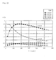
[Table 2] (f/Da) 1.05 0.95 0.90 0.85 0.80 0.75 Da 1200 -25200 22800 10800 6800 4800 3600 1100 -23100 20900 9900 6233.333 4400 3300 1000 -21000 19000 9000 5666.567 4000 3000 900 -18900 17100 8100 5100 3600 2700 800 -16800 15200 7200 4533.333 3200 2400 700 -14700 13300 6300 3966.667 2800 2100 600 -12600 11400 5400 3400 2400 1800 500 -10500 9500 4500 2833.333 2000 1500 - To determine an optimum value of r/p when the radius of an are that approximates the
curved part 13b is r (mm) and the length of one pitch is p (mm) for the cross-sectional shape of theunit prism 13u of the linear prism (see Fig. 5A), we assumed the following four types of shapes as theunit prism 13u, using the shape factors C and K of (Formula 1) which represents the shape of the above mentioned linear prism, projection distance a (mm) of the prism surface 13a of theunit prism 13u in the screen height direction, and the projection distance b (mm) of thecurved part 13b of theunit prism 13u in the screen height direction, and for each type we determined r/p in the area which distance Y (mm) is up to 500 mm from the screen center in the screen height direction. Figs. 11 - 14 show these four types of shapes. "Shape without r" in the figures is the case when the radius r of the curved part is "0", and the approximated shape is the case when the prism shape is approximated using the projection distance a and b. - (1) When the prism angle θ is small and the radius r of the curved part is large:

- (2) When the prism angle θ is small and the radius r of the curved part is small:

- (3) When the prism angle θ is large and the radius r of the curved part is large:

- (4) When the prism angle θ is large and the radius r of the curved part is small:

- Table 3 and Fig. 10 show this result. We confirmed that the shape of the unit prism of the working examples satisfy 0.1 - 4 of r/p. If r/p is smaller than this range, the ghost light becomes stronger, and if r/p is greater than this range, lights cannot be converged effectively. Therefore the optimum range of r/p is the above mentioned range.
[Table 3] r/p calculation example C=1.0E-4 C=1.0E-4 C=5.0E-4 C=5.0E-4 Distance 0 b=0.64 b=0.30 b=0.64 b=0.30 Y (mm) 25 0.123209 1.539469 0.380734 3.416615 50 0.215983 2.43162 0.475404 3.403164 75 0.286323 2.953379 0.488628 3.048273 100 0.339891 3.253527 0.475535 2.699433 125 0.380734 3.416615 0.454216 2. 403642 150 0.411826 3.492872 0.43127 2.159174 175 0.435363 3.513232 0.409189 1.95682 200 0.453022 3.497301 0.388865 1.78782 225 0.466044 3.457806 0.370533 1.645155 250 0.475404 3.403164 0.354158 1.523436 275 0.481855 3.339026 0.3396 1.418556 300 0.485984 3.26923 0.326687 1.327368 325 0.488256 3.196398 0.315244 1.24744 350 0.489039 3.122334 0.305109 1.176868 375 0.488628 3.048273 0.296138 1.114149 400 0.48726 2.975059 0.288203 1.058079 425 0.485126 2.903259 0.281193 1.007685 450 0.48238 2.833248 0.275011 0.962175 475 0.479148 13.75526 0.269574 0.920895 500 0.475535 2.699433 0.264809 0.883303 - According to the present invention, it is possible to increase the peak screen gain and to improve the peripheral luminance ratio when an observer views the screen, without degrading light utilization efficiency.
Claims (7)
- A rear projection screen (10) suitable for use in a projection optical system wherein image light projected by said system enters the screen face perpendicularly to the screen face,
wherein said screen (10) comprises a Fresnel lens sheet (11) and a lenticular lens sheet (12), and said Fresnel lens sheet (11) has a linear prism (13) on the surface at the projection light source side (1), and has a circular Fresnel lens (14) on the surface at the observer side (8), said linear prism (13) adapted to act as a linear Fresnel lens for converging the projected image light in the first screen direction (y), said circular Fresnel lens (14) being adapted to further converge the light emitted from the said linear prism (13) to the screen center direction, and said lenticular lens sheet (12) being adapted to disperse image light emitted from the Fresnel lens sheet (11) in the second screen direction (x) normal to the said first screen direction (y), and
wherein said linear prism comprises a plurality of unit prisms (13u), each unit prism (13u) having a prism angle (θ) and a prism height (h), the angle (θ) being defined between the unit prism face and a line parallel to the first screen direction (y), the height (h) being defined measured perpendicular to the first screen direction (y);
characterized in that the height (h) of the unit prisms (13u) increases continuously with respect to the distance (Y) from the screen center in the first screen direction (y) in order to improve the peripheral luminance ratio of the screen. - The rear projection screen (10) according to Claim 1, wherein the converging distance (Dv) in the first screen direction is shorter than the converging distance (Dh) in the second screen direction (x) of the screen (10) in the area outside of a 10% border line, where said 10%border line is positioned from the center point (10o) of the screen at a 10% distance of a distance between the center point (10o) and the screen edge in the said screen first direction (y).
- The rear projection screen (10) according to Claim 1 or 2, wherein 0.8 < f / Da < 1.0 is satisfied when the focal length of the circular Fresnel lens is f and the distance from the projection light source (1) to the Fresnel lens sheet (11) is Da.
- The rear projection screen (10) according to one or more of the preceding claims, wherein the cross-sectional shape of a unit prism (13u) composing the linear prism (13) is comprised of a straight line part (13a) and a curved part (13b) in the said first screen direction (y), and 0.1 ≤ r / p ≤ 4 , where p ≥ 0.05 mm and h ≥ 0.005 mm are satisfied when the pitch of the unit prism (13u) is p expressed in mm, the radius when the shape of the curved part (13b) is approximated with the circle is r expressed in mm, and the height of the prism is h expressed in mm.
- The rear projection screen (10) according to one or more of the preceding claims, wherein the prism angle (θ) of the linear prism (13) is 0° at the screen center area, and is 3° - 15° in the area outside of a 90% border line, where 90% border line positioned from the center point (100) at a 90% distance of a distance between the center point (100) and the screen edge in the said first screen direction (y).
- The rear projection screen (10) according to one or more of the preceding claims, wherein the lenticular lens sheet (12) is a double sided lenticular lens sheet which has a lenticular lens (12i) on the incident side surface and lenticular lens (12o) on the outgoing side surface of the projected light, respectively, and the apex of the lenticular lens (12o) on the outgoing side surface is formed roughly at a focusing position of the lenticular lens (12i) on the incident side surface.
- The rear projection screen (10) according to one or more of the preceding claims, wherein a flat area where no unit prisms (13u) are formed is disposed at the screen center area.
Applications Claiming Priority (2)
| Application Number | Priority Date | Filing Date | Title |
|---|---|---|---|
| JP34600797 | 1997-12-16 | ||
| JP34600797 | 1997-12-16 |
Publications (3)
| Publication Number | Publication Date |
|---|---|
| EP0924557A2 EP0924557A2 (en) | 1999-06-23 |
| EP0924557A3 EP0924557A3 (en) | 2000-02-02 |
| EP0924557B1 true EP0924557B1 (en) | 2007-04-18 |
Family
ID=18380506
Family Applications (1)
| Application Number | Title | Priority Date | Filing Date |
|---|---|---|---|
| EP98123503A Expired - Lifetime EP0924557B1 (en) | 1997-12-16 | 1998-12-15 | Rear projection screen incorporating a prism |
Country Status (3)
| Country | Link |
|---|---|
| US (1) | US6292295B1 (en) |
| EP (1) | EP0924557B1 (en) |
| DE (1) | DE69837591T2 (en) |
Families Citing this family (19)
| Publication number | Priority date | Publication date | Assignee | Title |
|---|---|---|---|---|
| KR100343964B1 (en) * | 1999-08-31 | 2002-07-22 | 엘지전자주식회사 | Projective Screen of Rear Projection Display Apparatus |
| JP2002090889A (en) | 2000-09-14 | 2002-03-27 | Kuraray Co Ltd | Rear projection screen and its manufacture |
| KR100396556B1 (en) * | 2001-10-09 | 2003-09-02 | 삼성전자주식회사 | Screen for projection television |
| JP2004077535A (en) * | 2002-08-09 | 2004-03-11 | Dainippon Printing Co Ltd | Fresnel lens sheet |
| JP2004170862A (en) * | 2002-11-22 | 2004-06-17 | Dainippon Printing Co Ltd | Fresnel lens |
| TWI256520B (en) * | 2003-02-04 | 2006-06-11 | Kuraray Co | Transmission type screen and rear projection type display apparatus |
| US7095558B2 (en) * | 2003-09-01 | 2006-08-22 | Hitachi, Ltd. | Image display device, rear projection type screen used in image display device, Fresnel lens sheet, and method of making Fresnel lens sheet |
| TWI240829B (en) * | 2003-12-12 | 2005-10-01 | Ind Tech Res Inst | Light-guide type diffusive uniform light device |
| JP4701640B2 (en) * | 2004-02-09 | 2011-06-15 | 株式会社日立製作所 | Screen, Fresnel lens sheet used therefor, and image display device using the same |
| JP4581491B2 (en) * | 2004-06-04 | 2010-11-17 | 株式会社日立製作所 | Screen, Fresnel lens sheet used therefor, and image display device using the same |
| JP5055765B2 (en) * | 2005-12-22 | 2012-10-24 | 株式会社日立製作所 | Image display device, and Fresnel lens sheet and screen used therefor |
| JP2007286183A (en) * | 2006-04-13 | 2007-11-01 | Sony Corp | Fresnel lens, prism array, rear projection type display apparatus, and illuminating device |
| DE102008020171B4 (en) * | 2008-04-22 | 2010-08-05 | Trw Automotive Electronics & Components Gmbh | Optical sensor device |
| US8042949B2 (en) | 2008-05-02 | 2011-10-25 | Microsoft Corporation | Projection of images onto tangible user interfaces |
| US8068187B2 (en) * | 2008-06-18 | 2011-11-29 | 3M Innovative Properties Company | Stereoscopic 3D liquid crystal display apparatus having a double sided prism film comprising cylindrical lenses and non-contiguous prisms |
| EP2287641B1 (en) * | 2009-08-21 | 2013-07-24 | Mass Technology (H.K.) Ltd. | Fresnel lens sheet and luminaire using the same |
| EP2752688A1 (en) * | 2013-01-04 | 2014-07-09 | Samsung Electronics Co., Ltd | Fresnel lens and pyroelectricity sensor module including the same |
| USD735400S1 (en) * | 2013-02-09 | 2015-07-28 | SVV Technology Innovations, Inc | Optical lens array lightguide plate |
| CN109634046B (en) * | 2018-12-24 | 2024-03-19 | 宁波激智科技股份有限公司 | Optical screen and preparation method thereof |
Family Cites Families (13)
| Publication number | Priority date | Publication date | Assignee | Title |
|---|---|---|---|---|
| US3972596A (en) | 1972-05-12 | 1976-08-03 | Donnelly Mirrors, Inc. | View expanding and directing optical system |
| JPS58153924A (en) * | 1982-03-10 | 1983-09-13 | Hitachi Ltd | Screen for projection |
| US4512631A (en) * | 1983-04-21 | 1985-04-23 | Rca Corporation | Rear projection television screen incorporating a prism lens |
| JPS60213534A (en) * | 1984-04-06 | 1985-10-25 | Makoto Okamura | Monitor |
| JPH0623817B2 (en) * | 1985-07-18 | 1994-03-30 | 旭光学工業株式会社 | LCD projection image display device |
| US4871233A (en) * | 1987-05-12 | 1989-10-03 | Sheiman David M | Thin plate prism and stereoscopic system |
| JPH0830848B2 (en) * | 1988-04-15 | 1996-03-27 | 株式会社日立製作所 | Multi-screen projector |
| JP2972271B2 (en) * | 1989-04-26 | 1999-11-08 | 株式会社日立製作所 | TRANSMISSION SCREEN AND METHOD OF MANUFACTURING SHEET-LIKE MEMBER USED FOR THE SAME, AND REAR PROJECTION DISPLAY USING THE SCREEN |
| DE69022974T2 (en) * | 1990-03-23 | 1996-04-25 | Zeni Lite Buoy Co Ltd | Cylindrical lens and associated manufacturing process. |
| JP2911627B2 (en) * | 1991-03-27 | 1999-06-23 | 株式会社日立製作所 | Large screen projection display |
| US5317349A (en) * | 1993-06-29 | 1994-05-31 | Minnesota Mining And Manufacturing Company | Overhead projector with achromatic fresnel lens |
| JP3390790B2 (en) * | 1993-08-31 | 2003-03-31 | 大日本印刷株式会社 | Projection screen |
| JPH08262566A (en) * | 1994-07-22 | 1996-10-11 | Mitsubishi Electric Corp | Projection type display device |
-
1998
- 1998-12-15 DE DE69837591T patent/DE69837591T2/en not_active Expired - Fee Related
- 1998-12-15 US US09/210,796 patent/US6292295B1/en not_active Expired - Fee Related
- 1998-12-15 EP EP98123503A patent/EP0924557B1/en not_active Expired - Lifetime
Also Published As
| Publication number | Publication date |
|---|---|
| DE69837591T2 (en) | 2007-12-27 |
| EP0924557A2 (en) | 1999-06-23 |
| EP0924557A3 (en) | 2000-02-02 |
| US6292295B1 (en) | 2001-09-18 |
| DE69837591D1 (en) | 2007-05-31 |
Similar Documents
| Publication | Publication Date | Title |
|---|---|---|
| EP0924557B1 (en) | Rear projection screen incorporating a prism | |
| US6407860B1 (en) | Fresnel lens sheet | |
| US7253954B2 (en) | Flat valley fresnel lens | |
| US4919518A (en) | Multi-screen projector | |
| US6995907B2 (en) | Diffusion sheet for use in transmission-type screen and transmission-type screen | |
| US20040114230A1 (en) | Rear projection display system | |
| US6502942B2 (en) | Rear projection display apparatus and translucent screen for use therein | |
| US7551352B2 (en) | Image display apparatus, as well as, Fresnel lens sheet and screen to be used therein | |
| US6762883B2 (en) | Lenticular lens sheet and rear projection screen | |
| JPS63132228A (en) | Rear projection screen | |
| JP3697832B2 (en) | Rear projection display device and screen unit | |
| JP2695422B2 (en) | Transmission screen | |
| EP1039337B1 (en) | Rear projection screen | |
| US6900945B2 (en) | Lenticular lens sheet | |
| JPH11271884A (en) | Rear projection type screen equipped with prism | |
| JP2000137294A (en) | Visual field control sheet, back surface projection type screen and back surface projection type display | |
| JPH02135332A (en) | Lenticular lens for rear projection type projection television | |
| US7061677B2 (en) | Screen for projection display in which the light is uniformly transmitted throughout the screen | |
| JP3712085B2 (en) | Lenticular lens sheet | |
| JPH0345987A (en) | Back project type display device | |
| JPH02153338A (en) | Backproject type screen and backproject type image display device using it | |
| JP2695420B2 (en) | Transmission screen | |
| KR100437060B1 (en) | Lcd device for a high-brightness single plate-type liquid crystal projector, specifically in relation to improving contrast of a liquid crystal or increasing lightness of the liquid crystal | |
| JPH02306231A (en) | Lens sheet for back transmission type screen | |
| JPH0345988A (en) | Backproject type display device |
Legal Events
| Date | Code | Title | Description |
|---|---|---|---|
| PUAI | Public reference made under article 153(3) epc to a published international application that has entered the european phase |
Free format text: ORIGINAL CODE: 0009012 |
|
| AK | Designated contracting states |
Kind code of ref document: A2 Designated state(s): DE FR GB NL |
|
| AX | Request for extension of the european patent |
Free format text: AL;LT;LV;MK;RO;SI |
|
| PUAL | Search report despatched |
Free format text: ORIGINAL CODE: 0009013 |
|
| AK | Designated contracting states |
Kind code of ref document: A3 Designated state(s): AT BE CH CY DE DK ES FI FR GB GR IE IT LI LU MC NL PT SE |
|
| AX | Request for extension of the european patent |
Free format text: AL;LT;LV;MK;RO;SI |
|
| 17P | Request for examination filed |
Effective date: 20000731 |
|
| AKX | Designation fees paid |
Free format text: DE FR GB NL |
|
| 17Q | First examination report despatched |
Effective date: 20020403 |
|
| GRAP | Despatch of communication of intention to grant a patent |
Free format text: ORIGINAL CODE: EPIDOSNIGR1 |
|
| GRAS | Grant fee paid |
Free format text: ORIGINAL CODE: EPIDOSNIGR3 |
|
| GRAJ | Information related to disapproval of communication of intention to grant by the applicant or resumption of examination proceedings by the epo deleted |
Free format text: ORIGINAL CODE: EPIDOSDIGR1 |
|
| GRAP | Despatch of communication of intention to grant a patent |
Free format text: ORIGINAL CODE: EPIDOSNIGR1 |
|
| GRAS | Grant fee paid |
Free format text: ORIGINAL CODE: EPIDOSNIGR3 |
|
| GRAA | (expected) grant |
Free format text: ORIGINAL CODE: 0009210 |
|
| AK | Designated contracting states |
Kind code of ref document: B1 Designated state(s): DE FR GB NL |
|
| REF | Corresponds to: |
Ref document number: 69837591 Country of ref document: DE Date of ref document: 20070531 Kind code of ref document: P |
|
| ET | Fr: translation filed | ||
| NLV1 | Nl: lapsed or annulled due to failure to fulfill the requirements of art. 29p and 29m of the patents act | ||
| PG25 | Lapsed in a contracting state [announced via postgrant information from national office to epo] |
Ref country code: NL Free format text: LAPSE BECAUSE OF FAILURE TO SUBMIT A TRANSLATION OF THE DESCRIPTION OR TO PAY THE FEE WITHIN THE PRESCRIBED TIME-LIMIT Effective date: 20070418 |
|
| PLBE | No opposition filed within time limit |
Free format text: ORIGINAL CODE: 0009261 |
|
| STAA | Information on the status of an ep patent application or granted ep patent |
Free format text: STATUS: NO OPPOSITION FILED WITHIN TIME LIMIT |
|
| 26N | No opposition filed |
Effective date: 20080121 |
|
| PGFP | Annual fee paid to national office [announced via postgrant information from national office to epo] |
Ref country code: GB Payment date: 20071212 Year of fee payment: 10 Ref country code: FR Payment date: 20071210 Year of fee payment: 10 |
|
| PGFP | Annual fee paid to national office [announced via postgrant information from national office to epo] |
Ref country code: DE Payment date: 20071213 Year of fee payment: 10 |
|
| GBPC | Gb: european patent ceased through non-payment of renewal fee |
Effective date: 20081215 |
|
| REG | Reference to a national code |
Ref country code: FR Ref legal event code: ST Effective date: 20090831 |
|
| PG25 | Lapsed in a contracting state [announced via postgrant information from national office to epo] |
Ref country code: DE Free format text: LAPSE BECAUSE OF NON-PAYMENT OF DUE FEES Effective date: 20090701 |
|
| PG25 | Lapsed in a contracting state [announced via postgrant information from national office to epo] |
Ref country code: GB Free format text: LAPSE BECAUSE OF NON-PAYMENT OF DUE FEES Effective date: 20081215 |
|
| PG25 | Lapsed in a contracting state [announced via postgrant information from national office to epo] |
Ref country code: FR Free format text: LAPSE BECAUSE OF NON-PAYMENT OF DUE FEES Effective date: 20081231 |