EP0924497A1 - Flache batteriebetriebene Waage - Google Patents
Flache batteriebetriebene Waage Download PDFInfo
- Publication number
- EP0924497A1 EP0924497A1 EP98119358A EP98119358A EP0924497A1 EP 0924497 A1 EP0924497 A1 EP 0924497A1 EP 98119358 A EP98119358 A EP 98119358A EP 98119358 A EP98119358 A EP 98119358A EP 0924497 A1 EP0924497 A1 EP 0924497A1
- Authority
- EP
- European Patent Office
- Prior art keywords
- pan
- weighing
- handlebars
- strain gauges
- load receiver
- Prior art date
- Legal status (The legal status is an assumption and is not a legal conclusion. Google has not performed a legal analysis and makes no representation as to the accuracy of the status listed.)
- Withdrawn
Links
Images

Classifications
-
- G—PHYSICS
- G01—MEASURING; TESTING
- G01G—WEIGHING
- G01G21/00—Details of weighing apparatus
- G01G21/24—Guides or linkages for ensuring parallel motion of the weigh-pans
- G01G21/244—Guides or linkages for ensuring parallel motion of the weigh-pans combined with flexure-plate fulcrums
-
- H—ELECTRICITY
- H01—ELECTRIC ELEMENTS
- H01M—PROCESSES OR MEANS, e.g. BATTERIES, FOR THE DIRECT CONVERSION OF CHEMICAL ENERGY INTO ELECTRICAL ENERGY
- H01M50/00—Constructional details or processes of manufacture of the non-active parts of electrochemical cells other than fuel cells, e.g. hybrid cells
- H01M50/20—Mountings; Secondary casings or frames; Racks, modules or packs; Suspension devices; Shock absorbers; Transport or carrying devices; Holders
- H01M50/204—Racks, modules or packs for multiple batteries or multiple cells
- H01M50/207—Racks, modules or packs for multiple batteries or multiple cells characterised by their shape
- H01M50/216—Racks, modules or packs for multiple batteries or multiple cells characterised by their shape adapted for button or coin cells
-
- G—PHYSICS
- G01—MEASURING; TESTING
- G01G—WEIGHING
- G01G23/00—Auxiliary devices for weighing apparatus
- G01G23/005—Means for preventing overload
-
- Y—GENERAL TAGGING OF NEW TECHNOLOGICAL DEVELOPMENTS; GENERAL TAGGING OF CROSS-SECTIONAL TECHNOLOGIES SPANNING OVER SEVERAL SECTIONS OF THE IPC; TECHNICAL SUBJECTS COVERED BY FORMER USPC CROSS-REFERENCE ART COLLECTIONS [XRACs] AND DIGESTS
- Y02—TECHNOLOGIES OR APPLICATIONS FOR MITIGATION OR ADAPTATION AGAINST CLIMATE CHANGE
- Y02E—REDUCTION OF GREENHOUSE GAS [GHG] EMISSIONS, RELATED TO ENERGY GENERATION, TRANSMISSION OR DISTRIBUTION
- Y02E60/00—Enabling technologies; Technologies with a potential or indirect contribution to GHG emissions mitigation
- Y02E60/10—Energy storage using batteries
Definitions
- the invention relates to an upper pan scale with a housing with a weighing pan, with a load receiver, which is characterized by a parallel guide an upper handlebar and a lower handlebar with a housing-fixed System carrier is connected, one of the handlebars being divided into two partial links is, which - seen from above - on both sides of the undivided handlebar are so that the handlebars do not overlap, while still the Load receptors, the handlebar and the system support form an integral part, and with strain gauges on at least one of the handlebars to generate a load-dependent electrical signal.
- Scales of this type are e.g. from DE-OS 44 27 088 or - with the exception of one-piece training of load receptors, handlebars and system carriers - too already known from DE-AS 20 09 858.
- a disadvantage of the known designs is that the weighing system is relatively large Takes up space.
- the object of the invention is therefore a balance of the type mentioned to further develop that it can be used as a portable, battery-operated scale.
- the construction should be as flat as possible without the Stability of the scale is reduced too much.
- the one-piece part two Breakthroughs for two batteries shows that the system carrier between the extends through two battery openings that the load receiver is approximately U-shaped is formed and the two legs of the U laterally next to the Battery breakthroughs and that the strain gauges only on the Are arranged inside the undivided handlebar.
- This configuration of the one-piece part results in a space-saving Arrangement:
- the system carrier is practically between the batteries and Parts of the load receiver are arranged around the batteries.
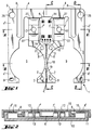
- the one-piece part 1 shown in Fig. 1 includes a system carrier 2, the Has holes 3, so that it to the housing not shown in Fig. 1 z. B. can be screwed on.
- the one-piece part also includes one Load receiver 4/4 ', which is approximately U-shaped and its lateral Leg 4 'are shaped so that between each leg 4' and System carrier 2 each have a circular cavity (opening) 5 for receiving each a battery is created.
- the one-piece part includes a lower one Handlebar 6 and an upper link 7, the upper link in two partial links 7 ' and 7 "is divided.
- the two links 6 and 7 form a in a known manner Parallel guidance, which moves the load receiver 4 in the vertical direction connects the system-fixed system carrier 2.
- Fig. 2 is a vertical section along the line A-A in Fig. 1
- Fig. 4 is a vertical section along the line C-C in Fig. 1.
- the lower Handlebar 6 is located on the underside of the one-piece part 1, the upper one Handlebar 7 on the top, so that the vertical distance between the top and lower handlebar is as large as possible for a given thickness of the one-piece part.
- the strain gauges 14 are only on the top of the lower link 6 attached and therefore extend - just like the associated ones Soldering points (17 in Fig. 1 and 4) and the associated wiring (lines 18 in Fig. 1 and 4) - only in the interior of the one-piece part 1 and therefore do not increase the height of the scale, as strain gauges do the bottom of the lower handlebar 6 would do.
- the weighing pan 15 is supported at four points on the normal weighing operation Load receiver 4/4 '/ 4' 'from: In the two legs 4' of the load receiver there is a recess 9 '(can be seen in Fig. 1 and 5), in the hemispherical ridges 16 'on the underside of the weighing pan 15 protrude and also fix the weighing pan against lateral forces. On the arms 4 '' are only on the weighing pan 15, each with a round intermediate piece 16 (recognizable in FIGS. 2 and 5) at the support point 9 (in FIG. 1).
- the force transmitted from the weighing pan 15 to the load receiver 4 leads to an elastic bending of the handlebars 6 and 7, which in turn by the Strain gauges 14 on the handlebar 6 converted into an electrical signal becomes.
- This electrical signal is in a downstream electronics amplified, digitized and displayed in a display unit. - All these Electronic parts of the scales are state of the art and therefore not here individual explained.
- Fig. 2 you can also see measures to secure the scale against Overload.
- the weighing pan 15 is supported on the side walls 11 of the housing 10/11.
- the lower housing part (housing base) 10 two supports (ridges) 13, which are through holes (openings) 12 in divided handlebars 7 'and 7' 'extend through and also the central areas support the weighing pan 15 in the event of an overload and thus deflect the weighing pan 15 prevent.
- Appropriate supports can also be used at other points in the Lower housing part 10 may be provided.
- the arms 4 '' have the the slot 8 are separated from the rest of the load sensor 4, not the full height of the remaining one-piece part 1 on the arms 4 "are so far weakened that their spring constant is as large as the spring constant of Leg 4 'of the load receiver. This lowers the weighing pan 15 central load without tilting.
- the arms 4 '' and the legs 4 ' are also so resilient that the forces that occur when the weighing pan 15th be transferred to the load receiver 4 on their overload stops, which Do not overload handlebars 6 and 7. -
- the necessary Resilience of the arms 4 '' and the legs 4 ' also by a corresponding narrower design can be achieved.
- Fig. 3 which is a vertical section through the one-piece part 1 along the dashed line B-B in Fig. 1 and through the housing 10/11 recognizes one that the leg 4 'is slightly less high than the rest of the one-piece Part 1 can be designed to ensure the equality of the spring constants of the legs 4 'and the arms 4' 'and to make this spring constant sufficiently small do.
- the lower housing part 10 two Has battery compartments 20, which are in the cavities 5 of the one-piece part 1st extend into it.
- the battery compartments 20 rest on the system carrier 2 and thus increase its stiffness, while compared to the legs 4 'of the Load receiver are of course spaced.
- the two batteries are inserted from below; the means of electrical Contact and the cap for the battery compartments are the Not shown for clarity.
- the battery compartments 20 do not increase only the stability of the housing 10/11 and the housing-fixed system carrier 2, they also serve as a large-scale overload stop for the weighing pan 15.
- the Strain gauges 14 can e.g. from four individual strain gauges consist of a common slide. As a position aid when sticking the Strain gauge film can be seen in Fig. 1 and 4, a small step 21 the top of the lower handlebar 6 Strain gauge film pushed to this stage 21 and fixed there.
- a step 22 can be seen in FIG. 4 in the lower housing part 10.
- the system carrier 2 is directly on the lower housing part 10 attached, to the right of step 22 have the handlebar 6 and the load sensor 4th Space to compress under load.
- the Load receiver 4 supported by the lower housing part 10.
- a vertical section through the one-piece part 1 of Fig. 1 along the dashed line D-D, through the lower housing part 10 and through the Weighing pan 15 shown it can still be seen how the weighing pan 15 is mounted how it is secured against taking off and how it is protected for the Can be locked when not in use.
- the weighing pan has two pawls 30 which, when mounted in corresponding holes 32 in the side wall 11 are pushed in, and two pawls 31, which in corresponding openings in Housing next to the weighing pan. Jacks 30 and 31 have play and on all sides in the normal weighing position shown in FIG secure the weighing pan 15 against lifting.
- the weighing pan 15 is locked by lateral displacement (to the right in FIG. 5) become.
- the pawls 30 with their bulge 34 in the holes 32 fixed, the pawls 31 snap behind the projections 33, continue to push the round spacers 16 through the holes 29 in the arms 4 '' of the Load receiver and the hemispheres (ridges) 16 'slide out of the Depressions 9 'out.
- This will make the connections between the Weighing pan 15 and the load receiver 4/4 '/ 4' 'interrupted and none Forces are transferred to the load receiver.
- the weighing pan is held by the pawls 31 and can only be overcome a rash resistor can be pushed back into the normal weighing position.
- other configurations of this locking device are also possible.
- the one-piece part 1 can e.g. from a piece of sheet metal by milling from above and be made from below. - Of course it can also be the other way around be installed so that the upper link becomes the lower link and vice versa. This reversal does not change the function. Only that Wells 9 'for fixing the weighing pan 15 must then of course on the be attached to the other side of the one-piece part 1.
Landscapes
- Physics & Mathematics (AREA)
- General Physics & Mathematics (AREA)
- Chemical & Material Sciences (AREA)
- Chemical Kinetics & Catalysis (AREA)
- Electrochemistry (AREA)
- General Chemical & Material Sciences (AREA)
- Measurement Of Force In General (AREA)
- Battery Mounting, Suspending (AREA)
- Machines For Laying And Maintaining Railways (AREA)
- Cookers (AREA)
Abstract
Description
- Fig. 1
- das einstückige Teil, das Lastaufnehmer, Lenker und Systemträger bildet, in Aufsicht,
- Fig. 2
- einen vertikalen Schnitt durch das einstückige Teil aus Fig. 1 längs der gestrichelten Linie A-A in Fig. 1, durch das Gehäuseunterteil und durch die Waagschale,
- Fig. 3
- einen vertikalen Schnitt durch das einstückige Teil aus Fig. 1 längs der gestrichelten Linie B-B in Fig. 1 und durch das Gehäuseunterteil,
- Fig. 4
- einen vertikalen Schnitt durch das einstückige Teil aus Fig. 1 längs der gestrichelten Linie C-C, in Fig. 1 und durch das Gehäuseunterteil und
- Fig. 5
- einen vertikalen Schnitt durch das einstückige Teil aus Fig. 1 längs der gestrichelten Linie D-D in Fig. 1, durch das Gehäuseunterteil und durch die Waagschale.
Claims (10)
- Oberschalige Waage mit einem Gehäuse, mit einer Waagschale, mit einem Lastaufnehmer, der durch eine Parallelführung aus einem oberen Lenker und einem unteren Lenker mit einem gehäusfesten Systemträger verbunden ist, wobei einer der Lenker in zwei Teillenker unterteilt ist, die sich - in Aufsicht gesehen - auf beiden Seiten des ungeteilten Lenkers befinden, so daß sich die Lenker nicht überdecken, wobei weiterhin der Lastaufnehmer, die Lenker und der Systemträger ein einstückiges Teil bilden, und mit Dehnungsmeßstreifen auf mindestens einem der Lenker zur Erzeugung eines belastungsabhängigen elektrischen Signals, dadurch gekennzeichnet, daß das einstückige Teil (1) zwei Durchbrüche (5) für zwei Batterien aufweist, daß sich der Systemträger (2) zwischen den beiden Batteriedurchbrüchen (5) hindurch erstreckt, daß der Lastaufnehmer (4,4',4'') etwa U-förmig ausgebildet ist und die beiden Schenkel (4') des U sich seitlich neben den Batteriedurchbrüchen (5) befinden und daß die Dehnungsmeßstreifen (14) nur auf der Innenseite des ungeteilten Lenkers (6) angeordnet sind.
- Oberschalige Waage nach Anspruch 1, dadurch gekennzeichnet, daß im Lastaufnehmer (4) durch zwei Schlitze (8) zwei federnde Arme (4'') abgetrennt sind, die je einen Auflagepunkt (9) für die Waagschale (15) auf dem Lastaufnehmer (4) bilden.
- Oberschalige Waage nach einem der Ansprüche 1 oder 2, dadurch gekennzeichnet, daß der Gehäuseboden (10) an mehreren Stellen Erhöhungen (13) aufweist, die als Überlastanschläge für die Waagschale (15) dienen.
- Oberschalige Waage nach Anspruch 3, dadurch gekennzeichnet, daß die beiden Teillenker (7',7'') des geteilten Lenkers (7) etwa in der Mitte Durchbrüche (12) aufweisen, durch die hindurch sich zwei Erhöhungen (13) des Gehäusebodens (10) als Überlastanschläge erstrecken.
- Oberschalige Waage nach einem der Ansprüche 1 bis 4, dadurch gekennzeichnet, daß in den Gehäuseboden (10) zwei nach unten offene Batteriefächer (20) integriert sind, die sich in die beiden Batteriedurchbrüche (5) des einstückigen Teiles (1) hinein erstrecken und daß diese Batteriefächer (20) gleichzeitig Überlastanschläge für die Waagschale (15) bilden.
- Oberschalige Waage nach einem der Ansprüche 1 bis 5, dadurch gekennzeichnet, daß der Systemträger (2) eine Nut (19) aufweist, in der die Leitungen (18) zum Anschluß der Dehnungsmeßstreifen (14) verlegt sind.
- Oberschalige Waage nach einem der Ansprüche 1 bis 6, dadurch gekennzeichnet, daß vier Dehnungsmeßstreifen (14) auf einer gemeinsamen Folie auf der Innenseite des ungeteilten Lenkers (6) angeordnet sind.
- Oberschalige Waage nach einem der Ansprüche 1 bis 7, dadurch gekennzeichnet, daß der ungeteilte Lenker (6) auf seiner Innenseite eine Stufe (21) aufweist, die als Positionierhilfe beim Aufkleben der Dehnungsmeßstreifen (14) dient.
- Oberschalige Waage nach einem der Ansprüche 1 bis 8, dadurch gekennzeichnet, daß die Elektronik der Waage und die Anzeige sich neben dem einstückigen Teil (1) befinden.
- Oberschalige Waage nach einem der Ansprüche 1 bis 9, dadurch gekennzeichnet, daß die Waagschale (15) aus ihrer normalen Wägestellung heraus seitlich versehiebbar ist und im verschobenen Zustand am Gehäuse (10,11) fixiert ist.
Applications Claiming Priority (2)
| Application Number | Priority Date | Filing Date | Title |
|---|---|---|---|
| DE19756719A DE19756719C1 (de) | 1997-12-19 | 1997-12-19 | Flache batteriebetriebene Waage |
| DE19756719 | 1997-12-19 |
Publications (1)
| Publication Number | Publication Date |
|---|---|
| EP0924497A1 true EP0924497A1 (de) | 1999-06-23 |
Family
ID=7852644
Family Applications (1)
| Application Number | Title | Priority Date | Filing Date |
|---|---|---|---|
| EP98119358A Withdrawn EP0924497A1 (de) | 1997-12-19 | 1998-10-14 | Flache batteriebetriebene Waage |
Country Status (6)
| Country | Link |
|---|---|
| US (1) | US6211472B1 (de) |
| EP (1) | EP0924497A1 (de) |
| JP (1) | JP2983980B2 (de) |
| CN (1) | CN1133869C (de) |
| DE (2) | DE19756719C1 (de) |
| TW (1) | TW365649B (de) |
Families Citing this family (5)
| Publication number | Priority date | Publication date | Assignee | Title |
|---|---|---|---|---|
| US9018545B2 (en) * | 2012-09-28 | 2015-04-28 | Symbol Technologies, Inc. | Arrangement for and method of preventing overhanging weighing platter of scale from tipping at product checkout system and method of mounting and removing the weighing platter without tools |
| US10309823B2 (en) * | 2016-01-08 | 2019-06-04 | Withings | Thin weighing scale with a sandwich structure |
| US10151623B2 (en) * | 2016-07-28 | 2018-12-11 | Hall Labs, Llc | Thin weight scale |
| USD1031246S1 (en) * | 2022-03-04 | 2024-06-18 | Nike, Inc. | Shoe |
| USD1005662S1 (en) * | 2022-03-04 | 2023-11-28 | Nike, Inc. | Shoe |
Citations (5)
| Publication number | Priority date | Publication date | Assignee | Title |
|---|---|---|---|---|
| US4177868A (en) * | 1978-01-30 | 1979-12-11 | Bio-Dynamics Inc. | Weight-measuring and display device |
| US4653822A (en) * | 1984-10-31 | 1987-03-31 | Canon Kabushiki Kaisha | Electronic apparatus with a battery |
| US4800973A (en) * | 1988-03-04 | 1989-01-31 | Shlomo Angel | Portable electronic scale of minimal thickness and weight |
| US5072799A (en) * | 1990-07-11 | 1991-12-17 | Pitney Bowes Inc. | Load cell supporting member and weighing scale incorporating the same |
| DE4427088A1 (de) * | 1994-07-30 | 1996-02-01 | Sartorius Gmbh | Oberschalige Waage mit einstückiger Parallelführung |
Family Cites Families (20)
| Publication number | Priority date | Publication date | Assignee | Title |
|---|---|---|---|---|
| GB1263182A (en) * | 1969-03-07 | 1972-02-09 | Avery Ltd W & T | Improvements in weighing apparatus |
| US3949822A (en) * | 1974-09-30 | 1976-04-13 | Jerry L. McCauley | Vehicle wheel weighing system |
| US4381826A (en) * | 1980-10-27 | 1983-05-03 | Mettler Instrumente Ag | Weighing scale of unitary construction |
| US4396079A (en) * | 1981-07-29 | 1983-08-02 | Sensor Developments, Inc. | Weighing system |
| US4433741A (en) * | 1982-04-12 | 1984-02-28 | General Electric Company | Strain gage scale |
| US4515232A (en) * | 1983-11-07 | 1985-05-07 | Hottinger Baldwin Measurements, Inc. | Platform transducer beams |
| US4598781A (en) * | 1984-05-25 | 1986-07-08 | Pitney Bowes Inc. | Load cell having a flexure connector |
| US4583607A (en) * | 1984-06-07 | 1986-04-22 | Pitney Bowes Inc. | Load cell assembly with adjustable stiffness |
| JPS61262621A (ja) * | 1985-05-16 | 1986-11-20 | Tokyo Electric Co Ltd | ロ−ドセル秤 |
| US4949799A (en) * | 1986-02-03 | 1990-08-21 | Wernimont T August | Electronic weighing structure |
| US4848493A (en) * | 1988-10-20 | 1989-07-18 | Revere Corporation Of America | Load sensing structure for weighing apparatus |
| US4993506A (en) * | 1989-12-11 | 1991-02-19 | Shlomo Angel | Mass-produced flat one-piece load cell and scales incorporating it |
| US5319161A (en) * | 1992-12-24 | 1994-06-07 | Pitney Bowes Inc. | Mechanism for preventing overload on a weighing scale |
| US5308934A (en) * | 1992-12-24 | 1994-05-03 | Pitney Bowes Inc. | Load cell scale mounting device |
| US5425278A (en) * | 1993-09-17 | 1995-06-20 | Pneumatic Scale Corporation | Weigh scale with sapphire load cell |
| JP2678880B2 (ja) * | 1994-03-17 | 1997-11-19 | 株式会社タニタ | 一体構成の薄型重量センサ |
| US5510581A (en) * | 1994-05-18 | 1996-04-23 | Angel; Shlomo | Mass-produced flat multiple-beam load cell and scales incorporating it |
| US5521334A (en) * | 1994-12-27 | 1996-05-28 | Pitney Bowes Inc. | Multiple overload protection for electronic scales |
| FR2734050B1 (fr) * | 1995-05-09 | 1997-07-11 | Seb Sa | Capteur de poids autoporteur et appareil de pesage comportant de tels capteurs |
| US5929391A (en) * | 1996-05-02 | 1999-07-27 | Measurement Specialties, Inc. | Load cell for an electrical weighing scale |
-
1997
- 1997-12-19 DE DE19756719A patent/DE19756719C1/de not_active Expired - Fee Related
-
1998
- 1998-07-22 DE DE29813066U patent/DE29813066U1/de not_active Expired - Lifetime
- 1998-10-12 TW TW087116862A patent/TW365649B/zh not_active IP Right Cessation
- 1998-10-14 EP EP98119358A patent/EP0924497A1/de not_active Withdrawn
- 1998-11-13 US US09/192,117 patent/US6211472B1/en not_active Expired - Lifetime
- 1998-11-26 CN CNB981228046A patent/CN1133869C/zh not_active Expired - Fee Related
- 1998-12-08 JP JP10348404A patent/JP2983980B2/ja not_active Expired - Fee Related
Patent Citations (5)
| Publication number | Priority date | Publication date | Assignee | Title |
|---|---|---|---|---|
| US4177868A (en) * | 1978-01-30 | 1979-12-11 | Bio-Dynamics Inc. | Weight-measuring and display device |
| US4653822A (en) * | 1984-10-31 | 1987-03-31 | Canon Kabushiki Kaisha | Electronic apparatus with a battery |
| US4800973A (en) * | 1988-03-04 | 1989-01-31 | Shlomo Angel | Portable electronic scale of minimal thickness and weight |
| US5072799A (en) * | 1990-07-11 | 1991-12-17 | Pitney Bowes Inc. | Load cell supporting member and weighing scale incorporating the same |
| DE4427088A1 (de) * | 1994-07-30 | 1996-02-01 | Sartorius Gmbh | Oberschalige Waage mit einstückiger Parallelführung |
Also Published As
| Publication number | Publication date |
|---|---|
| US6211472B1 (en) | 2001-04-03 |
| CN1133869C (zh) | 2004-01-07 |
| DE29813066U1 (de) | 1999-09-02 |
| TW365649B (en) | 1999-08-01 |
| JP2983980B2 (ja) | 1999-11-29 |
| DE19756719C1 (de) | 1999-04-08 |
| CN1229190A (zh) | 1999-09-22 |
| JPH11237276A (ja) | 1999-08-31 |
Similar Documents
| Publication | Publication Date | Title |
|---|---|---|
| DE69532163T2 (de) | Massenproduzierte kraftmesszelle mit flachen mehrfachbiegebalken und deren anwendung in waagen | |
| DE2924886C2 (de) | ||
| DE112007002443T5 (de) | Ausgleichsrasteradapter für Spielzeugkonstruktionssets | |
| EP1564534B1 (de) | Wägezellenmodul | |
| EP0924497A1 (de) | Flache batteriebetriebene Waage | |
| DE9312286U1 (de) | Hebebühne mit mehreren Tragarmen | |
| DE2711316C3 (de) | Elektronische Uhr | |
| DE69420455T2 (de) | In der Höhe verstellbare Plattform | |
| DE3014259C2 (de) | Vorrichtung zur Signalabgabe | |
| DE3203979C2 (de) | ||
| DE3618663C2 (de) | Kreuzbandgelenk für eine elektronische Waage | |
| EP0338371B1 (de) | Digital arbeitendes Schalt- bzw. Regelgerät, insbesondere Schaltuhr | |
| EP1118844B1 (de) | Abstützvorrichtung für eine Wägezelle und Waage mit einer Abstützvorrichtung | |
| DE3743526A1 (de) | Plattformwaage | |
| CH635194A5 (en) | Balance for the weighing of persons or loads | |
| DE102019112871B4 (de) | Wägemodul und Wägeeinrichtung | |
| DE8524187U1 (de) | Überlastsicherung für eine oberschalige Waage | |
| DE8438006U1 (de) | Elektronische Waage mit Kalibriergewicht | |
| EP0026449A1 (de) | Mehrfach-Druckschalter | |
| DE2152504C3 (de) | Einbaugehäuse für eine elektromechanische Wägezelle | |
| DE202025107725U1 (de) | Wiegeeinrichtung | |
| EP0600926A1 (de) | Wägezelle für eine elektronische waage. | |
| EP1075645B1 (de) | Elektronische waage für den mobilen einsatz | |
| EP0795968A2 (de) | Akku-Pack für ein elektronisches Handgerät | |
| DE202022105084U1 (de) | Tastatur und ihre Tastenstruktur zur Anzeige eines Sofortbildes |
Legal Events
| Date | Code | Title | Description |
|---|---|---|---|
| PUAI | Public reference made under article 153(3) epc to a published international application that has entered the european phase |
Free format text: ORIGINAL CODE: 0009012 |
|
| 17P | Request for examination filed |
Effective date: 19981014 |
|
| AK | Designated contracting states |
Kind code of ref document: A1 Designated state(s): CH FR GB LI |
|
| AX | Request for extension of the european patent |
Free format text: AL;LT;LV;MK;RO;SI |
|
| AKX | Designation fees paid |
Free format text: CH FR GB LI |
|
| REG | Reference to a national code |
Ref country code: DE Ref legal event code: 8566 |
|
| GRAP | Despatch of communication of intention to grant a patent |
Free format text: ORIGINAL CODE: EPIDOSNIGR1 |
|
| STAA | Information on the status of an ep patent application or granted ep patent |
Free format text: STATUS: THE APPLICATION IS DEEMED TO BE WITHDRAWN |
|
| 18D | Application deemed to be withdrawn |
Effective date: 20040309 |