EP0924015B1 - Procédé de revêtement d'une vis d'extrudeuse - Google Patents
Procédé de revêtement d'une vis d'extrudeuse Download PDFInfo
- Publication number
- EP0924015B1 EP0924015B1 EP98123099A EP98123099A EP0924015B1 EP 0924015 B1 EP0924015 B1 EP 0924015B1 EP 98123099 A EP98123099 A EP 98123099A EP 98123099 A EP98123099 A EP 98123099A EP 0924015 B1 EP0924015 B1 EP 0924015B1
- Authority
- EP
- European Patent Office
- Prior art keywords
- coating
- hardness
- wall
- crown
- raised part
- Prior art date
- Legal status (The legal status is an assumption and is not a legal conclusion. Google has not performed a legal analysis and makes no representation as to the accuracy of the status listed.)
- Expired - Lifetime
Links
- 238000000576 coating method Methods 0.000 title claims description 46
- 239000000463 material Substances 0.000 claims description 59
- 239000011248 coating agent Substances 0.000 claims description 40
- 235000019589 hardness Nutrition 0.000 claims description 39
- PXHVJJICTQNCMI-UHFFFAOYSA-N Nickel Chemical compound [Ni] PXHVJJICTQNCMI-UHFFFAOYSA-N 0.000 claims description 14
- 238000000034 method Methods 0.000 claims description 12
- 229910045601 alloy Inorganic materials 0.000 claims description 8
- 239000000956 alloy Substances 0.000 claims description 8
- 229910052759 nickel Inorganic materials 0.000 claims description 7
- 238000000151 deposition Methods 0.000 claims description 6
- 238000003466 welding Methods 0.000 claims description 6
- 230000008021 deposition Effects 0.000 claims description 5
- WFKWXMTUELFFGS-UHFFFAOYSA-N tungsten Chemical compound [W] WFKWXMTUELFFGS-UHFFFAOYSA-N 0.000 claims description 5
- 239000010937 tungsten Substances 0.000 claims description 5
- 229910052721 tungsten Inorganic materials 0.000 claims description 5
- 229910010293 ceramic material Inorganic materials 0.000 claims description 3
- 239000007769 metal material Substances 0.000 claims description 3
- 239000002184 metal Substances 0.000 description 6
- 229910052751 metal Inorganic materials 0.000 description 6
- 229910001092 metal group alloy Inorganic materials 0.000 description 6
- 238000001125 extrusion Methods 0.000 description 5
- 238000004898 kneading Methods 0.000 description 5
- 239000011324 bead Substances 0.000 description 4
- 229920001971 elastomer Polymers 0.000 description 4
- 239000012634 fragment Substances 0.000 description 4
- 238000002156 mixing Methods 0.000 description 4
- 238000009418 renovation Methods 0.000 description 4
- 239000000203 mixture Substances 0.000 description 3
- 239000005060 rubber Substances 0.000 description 3
- 229910001347 Stellite Inorganic materials 0.000 description 2
- AHICWQREWHDHHF-UHFFFAOYSA-N chromium;cobalt;iron;manganese;methane;molybdenum;nickel;silicon;tungsten Chemical compound C.[Si].[Cr].[Mn].[Fe].[Co].[Ni].[Mo].[W] AHICWQREWHDHHF-UHFFFAOYSA-N 0.000 description 2
- 239000011261 inert gas Substances 0.000 description 2
- 238000003754 machining Methods 0.000 description 2
- 238000004519 manufacturing process Methods 0.000 description 2
- 238000012544 monitoring process Methods 0.000 description 2
- 238000010008 shearing Methods 0.000 description 2
- 238000005299 abrasion Methods 0.000 description 1
- 239000010953 base metal Substances 0.000 description 1
- 238000005452 bending Methods 0.000 description 1
- 239000000919 ceramic Substances 0.000 description 1
- 239000002131 composite material Substances 0.000 description 1
- 238000005137 deposition process Methods 0.000 description 1
- 239000012895 dilution Substances 0.000 description 1
- 238000010790 dilution Methods 0.000 description 1
- 239000000806 elastomer Substances 0.000 description 1
- 239000000945 filler Substances 0.000 description 1
- 238000011010 flushing procedure Methods 0.000 description 1
- 238000010030 laminating Methods 0.000 description 1
- 230000002045 lasting effect Effects 0.000 description 1
- 239000002245 particle Substances 0.000 description 1
- 239000004033 plastic Substances 0.000 description 1
- 229920003023 plastic Polymers 0.000 description 1
- 238000002360 preparation method Methods 0.000 description 1
- 230000000717 retained effect Effects 0.000 description 1
- 239000000243 solution Substances 0.000 description 1
- 230000003313 weakening effect Effects 0.000 description 1
Images
Classifications
-
- B—PERFORMING OPERATIONS; TRANSPORTING
- B23—MACHINE TOOLS; METAL-WORKING NOT OTHERWISE PROVIDED FOR
- B23K—SOLDERING OR UNSOLDERING; WELDING; CLADDING OR PLATING BY SOLDERING OR WELDING; CUTTING BY APPLYING HEAT LOCALLY, e.g. FLAME CUTTING; WORKING BY LASER BEAM
- B23K9/00—Arc welding or cutting
- B23K9/04—Welding for other purposes than joining, e.g. built-up welding
- B23K9/044—Built-up welding on three-dimensional surfaces
-
- B—PERFORMING OPERATIONS; TRANSPORTING
- B29—WORKING OF PLASTICS; WORKING OF SUBSTANCES IN A PLASTIC STATE IN GENERAL
- B29C—SHAPING OR JOINING OF PLASTICS; SHAPING OF MATERIAL IN A PLASTIC STATE, NOT OTHERWISE PROVIDED FOR; AFTER-TREATMENT OF THE SHAPED PRODUCTS, e.g. REPAIRING
- B29C48/00—Extrusion moulding, i.e. expressing the moulding material through a die or nozzle which imparts the desired form; Apparatus therefor
- B29C48/25—Component parts, details or accessories; Auxiliary operations
- B29C48/36—Means for plasticising or homogenising the moulding material or forcing it through the nozzle or die
- B29C48/395—Means for plasticising or homogenising the moulding material or forcing it through the nozzle or die using screws surrounded by a cooperating barrel, e.g. single screw extruders
-
- B—PERFORMING OPERATIONS; TRANSPORTING
- B29—WORKING OF PLASTICS; WORKING OF SUBSTANCES IN A PLASTIC STATE IN GENERAL
- B29C—SHAPING OR JOINING OF PLASTICS; SHAPING OF MATERIAL IN A PLASTIC STATE, NOT OTHERWISE PROVIDED FOR; AFTER-TREATMENT OF THE SHAPED PRODUCTS, e.g. REPAIRING
- B29C48/00—Extrusion moulding, i.e. expressing the moulding material through a die or nozzle which imparts the desired form; Apparatus therefor
- B29C48/25—Component parts, details or accessories; Auxiliary operations
- B29C48/36—Means for plasticising or homogenising the moulding material or forcing it through the nozzle or die
- B29C48/50—Details of extruders
- B29C48/505—Screws
- B29C48/507—Screws characterised by the material or their manufacturing process
- B29C48/509—Materials, coating or lining therefor
-
- B—PERFORMING OPERATIONS; TRANSPORTING
- B29—WORKING OF PLASTICS; WORKING OF SUBSTANCES IN A PLASTIC STATE IN GENERAL
- B29C—SHAPING OR JOINING OF PLASTICS; SHAPING OF MATERIAL IN A PLASTIC STATE, NOT OTHERWISE PROVIDED FOR; AFTER-TREATMENT OF THE SHAPED PRODUCTS, e.g. REPAIRING
- B29C48/00—Extrusion moulding, i.e. expressing the moulding material through a die or nozzle which imparts the desired form; Apparatus therefor
- B29C48/25—Component parts, details or accessories; Auxiliary operations
- B29C48/36—Means for plasticising or homogenising the moulding material or forcing it through the nozzle or die
- B29C48/50—Details of extruders
- B29C48/505—Screws
- B29C48/59—Screws characterised by details of the thread, i.e. the shape of a single thread of the material-feeding screw
- B29C48/60—Thread tops
-
- B—PERFORMING OPERATIONS; TRANSPORTING
- B29—WORKING OF PLASTICS; WORKING OF SUBSTANCES IN A PLASTIC STATE IN GENERAL
- B29C—SHAPING OR JOINING OF PLASTICS; SHAPING OF MATERIAL IN A PLASTIC STATE, NOT OTHERWISE PROVIDED FOR; AFTER-TREATMENT OF THE SHAPED PRODUCTS, e.g. REPAIRING
- B29C48/00—Extrusion moulding, i.e. expressing the moulding material through a die or nozzle which imparts the desired form; Apparatus therefor
- B29C48/03—Extrusion moulding, i.e. expressing the moulding material through a die or nozzle which imparts the desired form; Apparatus therefor characterised by the shape of the extruded material at extrusion
Definitions
- the invention relates to equipment for mixing and / or plasticizing with a mechanical work and extrusion equipment of different materials such as for example rubber.
- This invention relates more particularly to a coating method providing protection against wear by contact friction between at least one part in rotation and a fixed part. It also relates to an extruder screw provided with this coating on at least some of its raised parts.
- the field of application of the invention is of course not only reserved to rubbers but can easily be extended to plastics and mixtures elastomers or any material that can be mixed and extruded after undergoing a more or less important mechanical work.
- extrusion machines composed of a metal mixing cylinder in which at minus a metal screw formed of a core surrounded by one or more threads is rotated.
- thread any raised part on the core and intended to knead / shear the base material (s) in order to be able to extrude the mixture obtained through a stream of a given profile.
- the material to be plasticized is introduced into the kneading cylinder of said machine and undergoes mechanical deformation work (mainly shearing) by the rotation of each internal screw; the dimensions of each screw and each thread are a function of the work required for laminating; the more important this work, the more screw will be very long in front of the diameter of its core.
- the material tends to oppose a significant mechanical resistance which causes more or less significant bending deformations of the core, said core then being able to come into contact with the inner wall of the cylinder.
- This contact results in wear of the top parts of the threads of the screws, i.e. the parts of the threads closest to each other and opposite the internal wall of the mixing cylinder.
- the same phenomenon occurs on the raised parts of the extrusion heads intended to push the plasticized material to the exterior of the extruder.
- a known coating process consists in carrying out, after manufacture of the screw, a alloy deposit by welding; a finishing operation is necessary and consists of a rectification of the thread surfaces to obtain the desired surface condition and dimensions. He is at note that, given the high hardness of the coating, this machining requires tools specific and that consequently the rectification operation is made more difficult by this fact.
- the top wall is located closest to the cylindrical body hollow compared to other points on the outer wall surface of the core and is bounded by side walls, the intersection of each of said side walls with said top wall forming an edge intended to cut (that is to say to shear) a material which can be plasticized by mechanical work.
- the width of the top part is defined as the dimension measured according to a direction parallel to the axis of rotation of the part to be coated.
- the method according to the invention applies equally to the manufacture of parts new than for the renovation of kneading and / or extruder parts after subsequent wear to use.
- the deposition of the material of hardness strictly lower than that of the other material can also be done before or after the deposition of the other material.
- the material deposited on and in the vicinity of at least one edge is a metallic material obtained, for example, by depositing a weld bead.
- the second material of hardness D2 composing the coating is a material chosen from nickel-based metallic materials of high hardness or among the ceramic materials of high hardness.
- the invention also relates to an extruder screw as claimed in claim 4.
- the coating material on and in the vicinity of the edge of the top part, performing the shearing work of the material to be laminated and / or extrude, has a hardness D 1 lower by at least 5 HRc than the hardness D2 of the material covering covering the rest of said top part.
- the coating obtained by the process according to the invention makes it possible to improve sensitive resistance to abrasion by friction while reducing the appearance of flaking phenomenon of usual coatings.
- An advantage of the coating according to the invention is that it makes it possible to widen the possibilities of choice of covering materials since it is then possible to use very hard materials in areas with little risk of chipping, said materials which can be chosen, for example, from nickel-based materials or from ceramic materials.
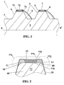
- This net 4 is delimited by two side walls 5 and 6 bearing on the wall external of the core 2 and by a top part 7 situated between said two walls side 5 and 6.
- the top part 7 of the net 4 is cylindrical and concentric with the external wall 3 of the core 2; this summit wall 7 is intended, once screw 1 in place in the kneading body of an extruder, to be located closer to the inner wall of said kneading body (not shown here).
- the part top 7 with a width of approximately 15 mm is provided with a covering layer with a thickness close to 1.5 mm, said layer according to the invention being formed, seen in the direction of axis XX ', of three parts placed side by side in direction XX'.
- a first part 71 and a third part 73 both made of a metallic alloy of hardness D1, cover the top wall 7 of the thread 4 in the vicinity of the two edges 8 and 9 determined respectively by the intersection of the side walls 5 and 6 of the net 4 with said top part 7; a second part 72 composed of a second metallic alloy hardness D2, D2 being strictly greater than D1 in the example presented, covers the part of the top wall 7 located between the edges 8 and 9 and not covered by the first part 71 and the third part 73 to form the covering.
- a screw 1 for an extruder comprising a thread 4 provided with a high-performance coating against contact wear and the phenomenon flaking under high shear stresses resulting from mixing work and / or extrusion of the materials to be extruded.
- the hardness difference is at least 5HRc.
- thicknesses of coating ranging from 0.5 mm to 4 mm.
- the coating materials are nickel-based alloys (advantageous from the point of view of welding characteristics and malleability therefore of formatting) and present hardnesses, for the parts close to edges, at most equal to 52 HRc (measured on the Rockwell scale) while for the intermediate part of the coating, the chosen alloy has a hardness close to 62 HRc.
- nickel-based metal alloys loaded with tungsten in proportions ranging from 30 to 60% so as to produce a composite material having improved resistance to wear by the presence of very high hardness tungsten filler (greater than 70HRc); an alloy loaded with tungsten will preferably be placed at the less on the middle part of the coating.
- Another interesting variant of coating is to use for at least the intermediate part of said coating a ceramic type material known for its characteristics of high hardness and its low coefficient of friction; this provision also offers the possibility, with retained wear performance, of a significant reduction of the thickness of said coating.
- Figure 2 is shown only part of a thread 77 of a screw extruder seen in cross section along a plane containing the axis of rotation of the screw carrying said net.
- the thread 77 of FIG. 2 corresponds to a thread on which we have represented superimposed on the different stages of the process according to the invention to allow a better understanding of said process.
Landscapes
- Engineering & Computer Science (AREA)
- Mechanical Engineering (AREA)
- Manufacturing & Machinery (AREA)
- Physics & Mathematics (AREA)
- Plasma & Fusion (AREA)
- Extrusion Moulding Of Plastics Or The Like (AREA)
- Processing And Handling Of Plastics And Other Materials For Molding In General (AREA)
Applications Claiming Priority (2)
| Application Number | Priority Date | Filing Date | Title |
|---|---|---|---|
| FR9716558A FR2772656A1 (fr) | 1997-12-22 | 1997-12-22 | Procede de revetement d'une vis d'extrudeuse |
| FR9716558 | 1997-12-22 |
Publications (2)
| Publication Number | Publication Date |
|---|---|
| EP0924015A1 EP0924015A1 (fr) | 1999-06-23 |
| EP0924015B1 true EP0924015B1 (fr) | 2003-08-27 |
Family
ID=9515177
Family Applications (1)
| Application Number | Title | Priority Date | Filing Date |
|---|---|---|---|
| EP98123099A Expired - Lifetime EP0924015B1 (fr) | 1997-12-22 | 1998-12-11 | Procédé de revêtement d'une vis d'extrudeuse |
Country Status (6)
| Country | Link |
|---|---|
| US (2) | US6155705A (enExample) |
| EP (1) | EP0924015B1 (enExample) |
| JP (1) | JP4294134B2 (enExample) |
| CN (1) | CN1098149C (enExample) |
| DE (1) | DE69817521T2 (enExample) |
| FR (1) | FR2772656A1 (enExample) |
Families Citing this family (23)
| Publication number | Priority date | Publication date | Assignee | Title |
|---|---|---|---|---|
| US6634781B2 (en) * | 2001-01-10 | 2003-10-21 | Saint Gobain Industrial Ceramics, Inc. | Wear resistant extruder screw |
| DE10352202B4 (de) * | 2003-11-05 | 2017-06-01 | Entex Rust & Mitschke Gmbh | Planetwalzenextruder mit Planetenspindeln und Anlaufring |
| US7316557B2 (en) * | 2004-05-08 | 2008-01-08 | Good Earth Tools, Inc. | Die for extruding material |
| US7513676B2 (en) | 2004-05-08 | 2009-04-07 | Good Earth Tools, Inc. | Extruder screw with long wearing surfaces |
| US8678637B2 (en) * | 2004-09-03 | 2014-03-25 | Leistritz Aktiengesellschaft | Extruder screw, extruder and shaft-hub connection |
| KR100857426B1 (ko) | 2007-05-11 | 2008-09-08 | 박상구 | 스크류의 이송블레이드 용접코팅장치 |
| US7934593B2 (en) * | 2007-10-10 | 2011-05-03 | Wam Industriale S.P.A. | Transport device |
| US20090098234A1 (en) * | 2007-10-11 | 2009-04-16 | Husky Injection Molding Systems Ltd. | Screw with Carbide Inserts |
| US8579623B2 (en) * | 2008-04-10 | 2013-11-12 | Edward Williams | Extruder stabilizer assembly |
| JP4926191B2 (ja) * | 2009-02-18 | 2012-05-09 | 株式会社日本製鋼所 | スクリュー及びその製造方法 |
| ES2637005T3 (es) | 2009-04-01 | 2017-10-10 | Mec Holding Gmbh | Rodillo resistente al desgaste y método para producirlo |
| JP5625444B2 (ja) * | 2010-03-30 | 2014-11-19 | 住友ベークライト株式会社 | 混練装置および半導体封止用樹脂組成物の製造方法 |
| KR101182095B1 (ko) | 2011-05-30 | 2012-09-19 | 주상규 | 용접코팅부가 형성된 스크류 및 이의 제작방법 |
| US10462963B2 (en) | 2012-03-06 | 2019-11-05 | Kondex Corporation | Laser clad cutting edge for agricultural cutting components |
| US9044820B2 (en) * | 2013-07-10 | 2015-06-02 | Kondex Corporation | Auger with laser cladding and/or laser heat treatment and method |
| EP2875891A1 (de) * | 2013-11-25 | 2015-05-27 | Böhler-Uddeholm Precision Strip GmbH | Verfahren zur Herstellung eines Vormaterials für ein Zerspanungswerkzeug und entsprechendes Vormaterial |
| BR202014001709Y1 (pt) * | 2014-01-24 | 2020-06-02 | João Augusto Streit | Rosca transportadora helicoidal produzida em aço ligado e temperada por indução eletromagnética ou chama |
| US9686911B2 (en) | 2014-05-12 | 2017-06-27 | Kondex Corporation | Cutting blade with transverse hardened regions |
| WO2015175418A1 (en) | 2014-05-12 | 2015-11-19 | Kondex Corporation | Slicing disc mower knives |
| US9717176B2 (en) | 2014-09-15 | 2017-08-01 | Kondex Corporation | Agricultural blades and machine parts with amorphous metal laser cladding |
| US10648051B2 (en) | 2015-04-24 | 2020-05-12 | Kondex Corporation | Reciprocating cutting blade with cladding |
| DE102020201895A1 (de) | 2020-02-17 | 2021-08-19 | Coperion Gmbh | Behandlungselement für eine Behandlungselementwelle einer Schneckenmaschine und Verfahren zum Herstellen eines Behandlungselements |
| CN116288333A (zh) * | 2023-02-25 | 2023-06-23 | 浙江栋斌橡塑螺杆有限公司 | 一种用于制作螺杆螺棱侧面上熔覆层的激光熔覆方法 |
Family Cites Families (24)
| Publication number | Priority date | Publication date | Assignee | Title |
|---|---|---|---|---|
| US3592128A (en) * | 1968-06-06 | 1971-07-13 | French Oil Mill Machinery | Screw press |
| US3968533A (en) * | 1973-04-23 | 1976-07-13 | Litton Fastening Systems | Fastener manufacturing apparatus |
| US3998318A (en) * | 1975-03-31 | 1976-12-21 | The Pantasote Company | Extruder screw |
| US4003115A (en) * | 1975-09-25 | 1977-01-18 | Bird Machine Company, Inc. | Method of making centrifuge conveyor |
| DE2745391A1 (de) * | 1977-10-08 | 1979-04-19 | Krupp Gmbh | Druckschnecke |
| AU8505082A (en) * | 1981-07-17 | 1983-01-20 | Deere & Company | Hardfacing |
| US4425044A (en) * | 1981-10-21 | 1984-01-10 | Union Carbide Corporation | Mixer heads for polyolefin extruders |
| US4440076A (en) * | 1982-02-08 | 1984-04-03 | Mansfield Pete W | System for improving efficiency of screw presses |
| US4449967A (en) * | 1982-06-17 | 1984-05-22 | Pennwalt Corporation | Conveyor flight configuration |
| JPS60153927A (ja) * | 1984-01-23 | 1985-08-13 | Masao Moriyama | 混練機等のブレイドの製造方法 |
| US4746220A (en) * | 1985-04-18 | 1988-05-24 | Noritake Co., Limited | Screw type extruding or kneading machine and screw used therein |
| JPH0677677B2 (ja) * | 1985-04-23 | 1994-10-05 | 三井東圧化学株式会社 | 混練装置 |
| JPS61266209A (ja) * | 1985-05-20 | 1986-11-25 | Hitachi Metals Ltd | 非磁性耐食、耐摩スクリユ− |
| US4838700A (en) * | 1987-04-30 | 1989-06-13 | Williamson Kirk E | Assemblies for a worm press |
| JPS63291632A (ja) * | 1987-05-25 | 1988-11-29 | Mitsubishi Heavy Ind Ltd | 可塑化スクリュ |
| DE3718779A1 (de) * | 1987-06-04 | 1988-12-22 | Krauss Maffei Ag | Schnecke od. dgl. maschinenteil fuer kunststoffverarbeitende maschinen |
| US4996919A (en) * | 1988-05-06 | 1991-03-05 | The Dupps Company | Bi-metal feed screw for screw presses |
| US5156860A (en) * | 1989-01-20 | 1992-10-20 | Idemitsu Petrochemical Co., Ltd. | Apparatus for manufacturing an optical disk substrate by injection molding |
| US5135378A (en) * | 1990-04-19 | 1992-08-04 | Catton Larry D | Extruder and screw with wear surfaces |
| US5348453A (en) * | 1990-12-24 | 1994-09-20 | James River Corporation Of Virginia | Positive displacement screw pump having pressure feedback control |
| US5088397A (en) * | 1991-01-11 | 1992-02-18 | The Dupps Co. | Cast formed bi-metallic worm assembly |
| US5429581A (en) * | 1994-03-07 | 1995-07-04 | Dorr-Oliver Incorporated | Wear-resistant tile surfacing for a centrifuge conveyor |
| US6085963A (en) * | 1994-05-26 | 2000-07-11 | Bgm (Patents) Limited | Work piece repair |
| US5673618A (en) * | 1996-03-11 | 1997-10-07 | Little; Ramond P. | Screw press flight with wear resistant surface |
-
1997
- 1997-12-22 FR FR9716558A patent/FR2772656A1/fr active Pending
-
1998
- 1998-12-11 DE DE69817521T patent/DE69817521T2/de not_active Expired - Fee Related
- 1998-12-11 EP EP98123099A patent/EP0924015B1/fr not_active Expired - Lifetime
- 1998-12-17 US US09/215,567 patent/US6155705A/en not_active Expired - Fee Related
- 1998-12-22 CN CN98125869A patent/CN1098149C/zh not_active Expired - Fee Related
- 1998-12-22 JP JP36506198A patent/JP4294134B2/ja not_active Expired - Fee Related
-
2000
- 2000-05-10 US US09/567,741 patent/US6346293B1/en not_active Expired - Fee Related
Also Published As
| Publication number | Publication date |
|---|---|
| JP4294134B2 (ja) | 2009-07-08 |
| US6346293B1 (en) | 2002-02-12 |
| DE69817521T2 (de) | 2004-06-17 |
| US6155705A (en) | 2000-12-05 |
| JPH11245282A (ja) | 1999-09-14 |
| EP0924015A1 (fr) | 1999-06-23 |
| CN1098149C (zh) | 2003-01-08 |
| DE69817521D1 (de) | 2003-10-02 |
| CN1221674A (zh) | 1999-07-07 |
| FR2772656A1 (fr) | 1999-06-25 |
Similar Documents
| Publication | Publication Date | Title |
|---|---|---|
| EP0924015B1 (fr) | Procédé de revêtement d'une vis d'extrudeuse | |
| EP1949995B1 (fr) | Fil electrode pour electroerosion | |
| EP2007544B1 (fr) | Procede de soudage par friction malaxage avec un dispositif a pion retractable avec retraction le pion retractable en fin de trajectoire | |
| WO2011064406A1 (fr) | Procede de realisation d' un renfort metallique d' aube de turbomachine | |
| FR2492296A1 (fr) | Fil pour soudage automatique a l'arc | |
| FR2843552A3 (fr) | Procede de realisation de jonctions integrees indetachables entre des matieres metalliques a dispersion d'oxydes(ods) ou de pieces en matieres metalliques a dispersion d'oxydes(ods) par soudage | |
| FR2962453A1 (fr) | Cable metallique a trois couches, gomme in situ par un elastomere thermoplastique insature | |
| EP2042618B1 (fr) | Procédé de récupération d'éléments de turbomachine | |
| EP3969213A1 (fr) | Procédé de fabrication additive pour une pièce métallique | |
| EP3402626B1 (fr) | Procédé et installation de fabrication d'un objet tridimensionnel | |
| EP3084112B1 (fr) | Élément de garniture de forage doté d'une couche de rechargement améliorée | |
| WO2018167384A1 (fr) | Procede de fabrication de pieces en alliage metallique de forme complexe | |
| EP2653260B1 (fr) | Procédé de fabrication de fil fourré par soudage laser avec préparation préalable des bords du feuillard | |
| EP2753455B1 (fr) | Meule de faconnage pour verre plat | |
| EP4251397B1 (fr) | Installation de coextrusion et procédé permettant de realiser une bande de roulement presentant des inserts de renfort enfouis en profondeur dans les blocs de sculpture | |
| EP3481570A2 (fr) | Procédé de fabrication additive avec enlèvement de matière entre deux couches | |
| FR2745208A1 (fr) | Procede de fabrication d'un fil stratifie de petit diametre et en particulier d'un fil electrode pour usinage par electroerosion et fil electrode obtenu | |
| FR2750638A1 (fr) | Moule d'injection et son procede de fabrication pour la realisation de pieces thermoplastiques | |
| EP4093606B1 (fr) | Elément de blindage anti-abrasion et procédé de fabrication associé | |
| EP0661136B1 (fr) | Procédé de rodage de la surface d'une pièce et rodoir pour la mise en oeuvre de ce procédé | |
| FR3122112A1 (fr) | Procédé de fabrication par injection-compression d’une roue dentée | |
| EP4587223A1 (fr) | Outil manuel d'ébavurage | |
| WO2025191222A1 (fr) | Procédé de réparation de pièces présentant un trou et dont la surface bordant le trou est détériorée | |
| WO2004069460A1 (fr) | Fil pour electroerosion a ame en laiton et couche superficielle en cuivre | |
| WO2020030778A1 (fr) | Electrode d'usinage par electroerosion par enfoncage, procede d'usinage par electroersion et procede de fabrication d'une telle electrode |
Legal Events
| Date | Code | Title | Description |
|---|---|---|---|
| PUAI | Public reference made under article 153(3) epc to a published international application that has entered the european phase |
Free format text: ORIGINAL CODE: 0009012 |
|
| AK | Designated contracting states |
Kind code of ref document: A1 Designated state(s): DE ES FR GB IT NL |
|
| AX | Request for extension of the european patent |
Free format text: AL;LT;LV;MK;RO;SI |
|
| 17P | Request for examination filed |
Effective date: 19991223 |
|
| AKX | Designation fees paid |
Free format text: DE ES FR GB IT NL |
|
| 17Q | First examination report despatched |
Effective date: 20020319 |
|
| GRAH | Despatch of communication of intention to grant a patent |
Free format text: ORIGINAL CODE: EPIDOS IGRA |
|
| GRAH | Despatch of communication of intention to grant a patent |
Free format text: ORIGINAL CODE: EPIDOS IGRA |
|
| GRAA | (expected) grant |
Free format text: ORIGINAL CODE: 0009210 |
|
| AK | Designated contracting states |
Designated state(s): DE ES FR GB IT NL |
|
| PG25 | Lapsed in a contracting state [announced via postgrant information from national office to epo] |
Ref country code: NL Free format text: LAPSE BECAUSE OF FAILURE TO SUBMIT A TRANSLATION OF THE DESCRIPTION OR TO PAY THE FEE WITHIN THE PRESCRIBED TIME-LIMIT Effective date: 20030827 Ref country code: IT Free format text: LAPSE BECAUSE OF FAILURE TO SUBMIT A TRANSLATION OF THE DESCRIPTION OR TO PAY THE FEE WITHIN THE PRESCRIBED TIME-LIMIT;WARNING: LAPSES OF ITALIAN PATENTS WITH EFFECTIVE DATE BEFORE 2007 MAY HAVE OCCURRED AT ANY TIME BEFORE 2007. THE CORRECT EFFECTIVE DATE MAY BE DIFFERENT FROM THE ONE RECORDED. Effective date: 20030827 |
|
| REG | Reference to a national code |
Ref country code: GB Ref legal event code: FG4D Free format text: NOT ENGLISH |
|
| REF | Corresponds to: |
Ref document number: 69817521 Country of ref document: DE Date of ref document: 20031002 Kind code of ref document: P |
|
| PG25 | Lapsed in a contracting state [announced via postgrant information from national office to epo] |
Ref country code: ES Free format text: LAPSE BECAUSE OF FAILURE TO SUBMIT A TRANSLATION OF THE DESCRIPTION OR TO PAY THE FEE WITHIN THE PRESCRIBED TIME-LIMIT Effective date: 20031208 |
|
| GBT | Gb: translation of ep patent filed (gb section 77(6)(a)/1977) |
Effective date: 20040107 |
|
| NLV1 | Nl: lapsed or annulled due to failure to fulfill the requirements of art. 29p and 29m of the patents act | ||
| PLBE | No opposition filed within time limit |
Free format text: ORIGINAL CODE: 0009261 |
|
| STAA | Information on the status of an ep patent application or granted ep patent |
Free format text: STATUS: NO OPPOSITION FILED WITHIN TIME LIMIT |
|
| 26N | No opposition filed |
Effective date: 20040528 |
|
| PGFP | Annual fee paid to national office [announced via postgrant information from national office to epo] |
Ref country code: GB Payment date: 20061221 Year of fee payment: 9 |
|
| GBPC | Gb: european patent ceased through non-payment of renewal fee |
Effective date: 20071211 |
|
| PG25 | Lapsed in a contracting state [announced via postgrant information from national office to epo] |
Ref country code: GB Free format text: LAPSE BECAUSE OF NON-PAYMENT OF DUE FEES Effective date: 20071211 |
|
| PGFP | Annual fee paid to national office [announced via postgrant information from national office to epo] |
Ref country code: FR Payment date: 20081212 Year of fee payment: 11 |
|
| PGFP | Annual fee paid to national office [announced via postgrant information from national office to epo] |
Ref country code: DE Payment date: 20081219 Year of fee payment: 11 |
|
| REG | Reference to a national code |
Ref country code: FR Ref legal event code: ST Effective date: 20100831 |
|
| PG25 | Lapsed in a contracting state [announced via postgrant information from national office to epo] |
Ref country code: FR Free format text: LAPSE BECAUSE OF NON-PAYMENT OF DUE FEES Effective date: 20091231 |
|
| PG25 | Lapsed in a contracting state [announced via postgrant information from national office to epo] |
Ref country code: DE Free format text: LAPSE BECAUSE OF NON-PAYMENT OF DUE FEES Effective date: 20100701 |