EP0924015B1 - Screw extruder coating process - Google Patents
Screw extruder coating process Download PDFInfo
- Publication number
- EP0924015B1 EP0924015B1 EP98123099A EP98123099A EP0924015B1 EP 0924015 B1 EP0924015 B1 EP 0924015B1 EP 98123099 A EP98123099 A EP 98123099A EP 98123099 A EP98123099 A EP 98123099A EP 0924015 B1 EP0924015 B1 EP 0924015B1
- Authority
- EP
- European Patent Office
- Prior art keywords
- coating
- hardness
- wall
- crown
- raised part
- Prior art date
- Legal status (The legal status is an assumption and is not a legal conclusion. Google has not performed a legal analysis and makes no representation as to the accuracy of the status listed.)
- Expired - Lifetime
Links
Images
Classifications
-
- B—PERFORMING OPERATIONS; TRANSPORTING
- B23—MACHINE TOOLS; METAL-WORKING NOT OTHERWISE PROVIDED FOR
- B23K—SOLDERING OR UNSOLDERING; WELDING; CLADDING OR PLATING BY SOLDERING OR WELDING; CUTTING BY APPLYING HEAT LOCALLY, e.g. FLAME CUTTING; WORKING BY LASER BEAM
- B23K9/00—Arc welding or cutting
- B23K9/04—Welding for other purposes than joining, e.g. built-up welding
- B23K9/044—Built-up welding on three-dimensional surfaces
-
- B—PERFORMING OPERATIONS; TRANSPORTING
- B29—WORKING OF PLASTICS; WORKING OF SUBSTANCES IN A PLASTIC STATE IN GENERAL
- B29C—SHAPING OR JOINING OF PLASTICS; SHAPING OF MATERIAL IN A PLASTIC STATE, NOT OTHERWISE PROVIDED FOR; AFTER-TREATMENT OF THE SHAPED PRODUCTS, e.g. REPAIRING
- B29C48/00—Extrusion moulding, i.e. expressing the moulding material through a die or nozzle which imparts the desired form; Apparatus therefor
- B29C48/25—Component parts, details or accessories; Auxiliary operations
- B29C48/36—Means for plasticising or homogenising the moulding material or forcing it through the nozzle or die
- B29C48/395—Means for plasticising or homogenising the moulding material or forcing it through the nozzle or die using screws surrounded by a cooperating barrel, e.g. single screw extruders
-
- B—PERFORMING OPERATIONS; TRANSPORTING
- B29—WORKING OF PLASTICS; WORKING OF SUBSTANCES IN A PLASTIC STATE IN GENERAL
- B29C—SHAPING OR JOINING OF PLASTICS; SHAPING OF MATERIAL IN A PLASTIC STATE, NOT OTHERWISE PROVIDED FOR; AFTER-TREATMENT OF THE SHAPED PRODUCTS, e.g. REPAIRING
- B29C48/00—Extrusion moulding, i.e. expressing the moulding material through a die or nozzle which imparts the desired form; Apparatus therefor
- B29C48/25—Component parts, details or accessories; Auxiliary operations
- B29C48/36—Means for plasticising or homogenising the moulding material or forcing it through the nozzle or die
- B29C48/50—Details of extruders
- B29C48/505—Screws
- B29C48/507—Screws characterised by the material or their manufacturing process
- B29C48/509—Materials, coating or lining therefor
-
- B—PERFORMING OPERATIONS; TRANSPORTING
- B29—WORKING OF PLASTICS; WORKING OF SUBSTANCES IN A PLASTIC STATE IN GENERAL
- B29C—SHAPING OR JOINING OF PLASTICS; SHAPING OF MATERIAL IN A PLASTIC STATE, NOT OTHERWISE PROVIDED FOR; AFTER-TREATMENT OF THE SHAPED PRODUCTS, e.g. REPAIRING
- B29C48/00—Extrusion moulding, i.e. expressing the moulding material through a die or nozzle which imparts the desired form; Apparatus therefor
- B29C48/25—Component parts, details or accessories; Auxiliary operations
- B29C48/36—Means for plasticising or homogenising the moulding material or forcing it through the nozzle or die
- B29C48/50—Details of extruders
- B29C48/505—Screws
- B29C48/59—Screws characterised by details of the thread, i.e. the shape of a single thread of the material-feeding screw
- B29C48/60—Thread tops
-
- B—PERFORMING OPERATIONS; TRANSPORTING
- B29—WORKING OF PLASTICS; WORKING OF SUBSTANCES IN A PLASTIC STATE IN GENERAL
- B29C—SHAPING OR JOINING OF PLASTICS; SHAPING OF MATERIAL IN A PLASTIC STATE, NOT OTHERWISE PROVIDED FOR; AFTER-TREATMENT OF THE SHAPED PRODUCTS, e.g. REPAIRING
- B29C48/00—Extrusion moulding, i.e. expressing the moulding material through a die or nozzle which imparts the desired form; Apparatus therefor
- B29C48/03—Extrusion moulding, i.e. expressing the moulding material through a die or nozzle which imparts the desired form; Apparatus therefor characterised by the shape of the extruded material at extrusion
Definitions
- the invention relates to equipment for mixing and / or plasticizing with a mechanical work and extrusion equipment of different materials such as for example rubber.
- This invention relates more particularly to a coating method providing protection against wear by contact friction between at least one part in rotation and a fixed part. It also relates to an extruder screw provided with this coating on at least some of its raised parts.
- the field of application of the invention is of course not only reserved to rubbers but can easily be extended to plastics and mixtures elastomers or any material that can be mixed and extruded after undergoing a more or less important mechanical work.
- extrusion machines composed of a metal mixing cylinder in which at minus a metal screw formed of a core surrounded by one or more threads is rotated.
- thread any raised part on the core and intended to knead / shear the base material (s) in order to be able to extrude the mixture obtained through a stream of a given profile.
- the material to be plasticized is introduced into the kneading cylinder of said machine and undergoes mechanical deformation work (mainly shearing) by the rotation of each internal screw; the dimensions of each screw and each thread are a function of the work required for laminating; the more important this work, the more screw will be very long in front of the diameter of its core.
- the material tends to oppose a significant mechanical resistance which causes more or less significant bending deformations of the core, said core then being able to come into contact with the inner wall of the cylinder.
- This contact results in wear of the top parts of the threads of the screws, i.e. the parts of the threads closest to each other and opposite the internal wall of the mixing cylinder.
- the same phenomenon occurs on the raised parts of the extrusion heads intended to push the plasticized material to the exterior of the extruder.
- a known coating process consists in carrying out, after manufacture of the screw, a alloy deposit by welding; a finishing operation is necessary and consists of a rectification of the thread surfaces to obtain the desired surface condition and dimensions. He is at note that, given the high hardness of the coating, this machining requires tools specific and that consequently the rectification operation is made more difficult by this fact.
- the top wall is located closest to the cylindrical body hollow compared to other points on the outer wall surface of the core and is bounded by side walls, the intersection of each of said side walls with said top wall forming an edge intended to cut (that is to say to shear) a material which can be plasticized by mechanical work.
- the width of the top part is defined as the dimension measured according to a direction parallel to the axis of rotation of the part to be coated.
- the method according to the invention applies equally to the manufacture of parts new than for the renovation of kneading and / or extruder parts after subsequent wear to use.
- the deposition of the material of hardness strictly lower than that of the other material can also be done before or after the deposition of the other material.
- the material deposited on and in the vicinity of at least one edge is a metallic material obtained, for example, by depositing a weld bead.
- the second material of hardness D2 composing the coating is a material chosen from nickel-based metallic materials of high hardness or among the ceramic materials of high hardness.
- the invention also relates to an extruder screw as claimed in claim 4.
- the coating material on and in the vicinity of the edge of the top part, performing the shearing work of the material to be laminated and / or extrude, has a hardness D 1 lower by at least 5 HRc than the hardness D2 of the material covering covering the rest of said top part.
- the coating obtained by the process according to the invention makes it possible to improve sensitive resistance to abrasion by friction while reducing the appearance of flaking phenomenon of usual coatings.
- An advantage of the coating according to the invention is that it makes it possible to widen the possibilities of choice of covering materials since it is then possible to use very hard materials in areas with little risk of chipping, said materials which can be chosen, for example, from nickel-based materials or from ceramic materials.
- This net 4 is delimited by two side walls 5 and 6 bearing on the wall external of the core 2 and by a top part 7 situated between said two walls side 5 and 6.
- the top part 7 of the net 4 is cylindrical and concentric with the external wall 3 of the core 2; this summit wall 7 is intended, once screw 1 in place in the kneading body of an extruder, to be located closer to the inner wall of said kneading body (not shown here).
- the part top 7 with a width of approximately 15 mm is provided with a covering layer with a thickness close to 1.5 mm, said layer according to the invention being formed, seen in the direction of axis XX ', of three parts placed side by side in direction XX'.
- a first part 71 and a third part 73 both made of a metallic alloy of hardness D1, cover the top wall 7 of the thread 4 in the vicinity of the two edges 8 and 9 determined respectively by the intersection of the side walls 5 and 6 of the net 4 with said top part 7; a second part 72 composed of a second metallic alloy hardness D2, D2 being strictly greater than D1 in the example presented, covers the part of the top wall 7 located between the edges 8 and 9 and not covered by the first part 71 and the third part 73 to form the covering.
- a screw 1 for an extruder comprising a thread 4 provided with a high-performance coating against contact wear and the phenomenon flaking under high shear stresses resulting from mixing work and / or extrusion of the materials to be extruded.
- the hardness difference is at least 5HRc.
- thicknesses of coating ranging from 0.5 mm to 4 mm.
- the coating materials are nickel-based alloys (advantageous from the point of view of welding characteristics and malleability therefore of formatting) and present hardnesses, for the parts close to edges, at most equal to 52 HRc (measured on the Rockwell scale) while for the intermediate part of the coating, the chosen alloy has a hardness close to 62 HRc.
- nickel-based metal alloys loaded with tungsten in proportions ranging from 30 to 60% so as to produce a composite material having improved resistance to wear by the presence of very high hardness tungsten filler (greater than 70HRc); an alloy loaded with tungsten will preferably be placed at the less on the middle part of the coating.
- Another interesting variant of coating is to use for at least the intermediate part of said coating a ceramic type material known for its characteristics of high hardness and its low coefficient of friction; this provision also offers the possibility, with retained wear performance, of a significant reduction of the thickness of said coating.
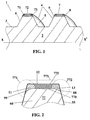
- Figure 2 is shown only part of a thread 77 of a screw extruder seen in cross section along a plane containing the axis of rotation of the screw carrying said net.
- the thread 77 of FIG. 2 corresponds to a thread on which we have represented superimposed on the different stages of the process according to the invention to allow a better understanding of said process.
Description
L'invention concerne le matériel pour mélanger et/ou de plastification par un travail mécanique et le matériel d'extrusion de différentes matières comme par exemple le caoutchouc. Cette invention concerne plus particulièrement un procédé de revêtement assurant la protection contre l'usure par frottement de contact entre au moins une pièce en rotation et une pièce fixe. Elle concerne également une vis pour extrudeuse pourvue de ce revêtement sur au moins certaines de ses parties en relief.The invention relates to equipment for mixing and / or plasticizing with a mechanical work and extrusion equipment of different materials such as for example rubber. This invention relates more particularly to a coating method providing protection against wear by contact friction between at least one part in rotation and a fixed part. It also relates to an extruder screw provided with this coating on at least some of its raised parts.
Sont notamment concernés par l'invention, les filets des vis de malaxage et d'extrusion ainsi que les parties en relief des têtes d'extrusion au voisinage des orifices d'éjection de la matière plastifiée, lesdites parties ayant pour fonction d'éjecter ladite matière.Are notably concerned by the invention, the threads of the kneading screws and as well as the raised parts of the extrusion heads in the vicinity of the orifices for ejecting the plasticized material, said parts having the function of ejecting said material.
Le domaine d'application de l'invention n'est bien entendu pas uniquement réservé aux caoutchoucs mais peut être aisément étendu aux matières plastiques et aux mélanges d'élastomères ou à toute matière pouvant être mélangée et extrudée après avoir subi un travail mécanique plus ou moins important.The field of application of the invention is of course not only reserved to rubbers but can easily be extended to plastics and mixtures elastomers or any material that can be mixed and extruded after undergoing a more or less important mechanical work.
Dans le domaine de la préparation des mélanges de caoutchouc, on emploie des machines d'extrusion composées d'un cylindre métallique de malaxage dans lequel au moins une vis métallique formée d'un noyau entouré d'un ou plusieurs filets de forme appropriée est mise en rotation.In the field of the preparation of rubber mixtures, extrusion machines composed of a metal mixing cylinder in which at minus a metal screw formed of a core surrounded by one or more threads is rotated.
Par filet, on entend toute partie en relief sur le noyau et destinée à malaxer / à cisailler la/les matière(s) de base afin de pouvoir extruder le mélange obtenu à travers une filière d'un profil donné.By thread is meant any raised part on the core and intended to knead / shear the base material (s) in order to be able to extrude the mixture obtained through a stream of a given profile.
La matière à plastifier est introduite dans le cylindre de malaxage de ladite machine et subit un travail mécanique de déformation (principalement de cisaillement) par la mise en rotation de chaque vis interne; les dimensions de chaque vis et de chaque filet sont fonction du travail nécessaire à la plastification; plus ce travail est important et plus la vis sera de grande longueur devant le diamètre de son noyau. Sous l'action de la rotation de la vis, la matière a tendance à opposer une importante résistance mécanique ce qui entraíne des déformations de flexion plus ou moins importantes du noyau, ledit noyau pouvant alors venir en contact avec la paroi interne du cylindre. De ce contact, il s'ensuit une usure des parties sommitales des filets des vis, c'est-à-dire des parties des filets situées au plus près et en regard de la paroi interne du cylindre de malaxage. Le même phénomène se produit sur les parties en relief des têtes d'extrusion destinées à pousser la matière plastifiée à l'extérieur de l'extrudeuse.The material to be plasticized is introduced into the kneading cylinder of said machine and undergoes mechanical deformation work (mainly shearing) by the rotation of each internal screw; the dimensions of each screw and each thread are a function of the work required for laminating; the more important this work, the more screw will be very long in front of the diameter of its core. Under the action of the rotation of the screw, the material tends to oppose a significant mechanical resistance which causes more or less significant bending deformations of the core, said core then being able to come into contact with the inner wall of the cylinder. This contact results in wear of the top parts of the threads of the screws, i.e. the parts of the threads closest to each other and opposite the internal wall of the mixing cylinder. The same phenomenon occurs on the raised parts of the extrusion heads intended to push the plasticized material to the exterior of the extruder.
Ce problème d'usure des filets de vis est bien connu et il a été proposé, pour
augmenter la durée de vie des pièces mobiles pouvant frotter contre des parties fixes tout
en maintenant un faible prix de revient, des vis d'extrudeuses dont les parties sommitales
des filets sont pourvues d'un revêtement à base d'un alliage métallique dont la
caractéristique en usure est améliorée par rapport à celle du matériau de base constitutif du
filet. On emploie par exemple des alliages dénommés Stellite 6 ou Stellite 12 dont les
caractéristiques de dureté et d'usure permettent d'améliorer de façon sensible la durée de
vie des vis d'extrudeuses.This problem of wear of the screw threads is well known and it has been proposed, for
increase the service life of moving parts that can rub against fixed parts while
while maintaining a low cost price, extruder screws, the top parts of which
nets are provided with a coating based on a metal alloy, the
wear characteristic is improved compared to that of the basic material constituting the
net. For example, alloys called Stellite 6 or
Un procédé de revêtement connu consiste à réaliser, après fabrication de la vis un dépôt d'alliage par soudure; une opération de finition est nécessaire et consiste en une rectification des surfaces de filet pour obtenir l'état de surface et les cotes désirées. Il est à noter que, compte tenu de la dureté élevée du revêtement, cet usinage nécessite un outillage spécifique et qu'en conséquence l'opération de rectification est rendue plus difficile de ce fait.A known coating process consists in carrying out, after manufacture of the screw, a alloy deposit by welding; a finishing operation is necessary and consists of a rectification of the thread surfaces to obtain the desired surface condition and dimensions. He is at note that, given the high hardness of the coating, this machining requires tools specific and that consequently the rectification operation is made more difficult by this fact.
L'expérience a montré que le dépôt d'un matériau de dureté maximale est préférable du point de vue de l'usure; toutefois les revêtements de dureté élevée, très performant en usure, présentent l'inconvénient d'être fragiles lorsqu'ils sont soumis aux sollicitations mécaniques de cisaillement qui sont par exemple celles rencontrées dans les extrudeuses. Il se produit ce que l'on appelle un phénomène d'écaillage consistant en ce que la surface du revêtement de dureté élevée se fissure dans un plan sensiblement parallèle à la surface sur laquelle agit la sollicitation. Progressivement, il se forme dans le revêtement un écaillage suivi d'un arrachement de fragments dudit revêtement; par fragment, on entend des morceaux de matière de taille sensiblement plus importante que la taille des particules formées habituellement par une usure régulière. Suite à cette fragilisation du dépôt de dureté élevée, il peut se faire que des fragments arrachés au revêtement se retrouvent dans la matière mélangée, ce qui se traduit par la présence d'éléments étrangers de taille relativement importante et pouvant affecter la performance desdits matériaux extrudés dans leur emploi ultérieur. Une conséquence de ce phénomène d'écaillage est qu'il est nécessaire de prévoir, pour éviter la présence de fragments de dépôt dans le matériau extrudé, un dispositif de surveillance de l'état de surface des filets; cette opération de surveillance implique bien entendu des surcoûts. En outre, les pièces revêtues nécessitent d'être renouvelées assez fréquemment; la restauration ou rénovation du dépôt est une opération qui est certes pratiquée mais qui reste néanmoins délicate à mettre en oeuvre avec des matériaux de revêtement de dureté élevée.Experience has shown that the deposition of a material of maximum hardness is preferable from the point of view of wear; however high hardness coatings, very effective in wear, have the disadvantage of being fragile when subjected to mechanical shear stresses which are, for example, those encountered in extruders. There is what is called a phenomenon of flaking consisting in that the surface of the high hardness coating cracks in a plane substantially parallel to the surface on which the stress acts. Gradually, it forms in the coating a flaking followed by tearing off of fragments of said coating; by fragment is meant pieces of material significantly larger than the particle size usually formed by regular wear. Following this weakening of the deposit of high hardness, it may be that fragments torn from the coating are found in mixed material, which results in the presence of foreign elements of size relatively large and may affect the performance of said extruded materials in their subsequent use. One consequence of this chipping phenomenon is that it is necessary to provide, to avoid the presence of fragments of deposit in the extruded material, a device for monitoring the surface condition of the nets; this monitoring operation of course involves additional costs. In addition, coated parts need to be renewed fairly frequently; restoration or renovation of the warehouse is an operation which is certainly practiced but which nevertheless remains delicate to implement with high hardness coating materials.
Selon un aspect de l'invention, il est proposé dans la revendication 1 un procédé de revêtement d'une paroi sommitale d'au moins une partie en relief sur la paroi externe d'un noyau tournant à l'intérieur d'un corps cylindrique creux présentant une paroi interne en regard de ladite paroi externe dudit noyau. La paroi sommitale est située au plus près du corps cylindrique creux comparativement aux autres points de la surface de paroi externe du noyau et est limitée par des parois latérales, l'intersection de chacune desdites parois latérales avec ladite paroi sommitale formant une arête destinée à couper (c'est-à-dire à cisailler) un matériau pouvant être plastifié par un travail mécanique.According to one aspect of the invention, there is provided in claim 1 a method of coating a wall apex of at least part in relief on the external wall of a core rotating at the interior of a hollow cylindrical body having an internal wall opposite said outer wall of said core. The top wall is located closest to the cylindrical body hollow compared to other points on the outer wall surface of the core and is bounded by side walls, the intersection of each of said side walls with said top wall forming an edge intended to cut (that is to say to shear) a material which can be plasticized by mechanical work.
Le procédé de revêtement des parties sommitales selon l'invention, conférant à ladite partie des propriétés d'endurance améliorées par rapport à celles habituellement obtenues avec les procédés connus, comporte les étapes suivantes :
- on dépose un premier matériau de
dureté D 1 sur et au voisinage d'au moins une arête de la partie sommitale de chaque partie en relief à revêtir et sur une fraction seulement de la largeur de ladite partie sommitale; - on dépose un deuxième matériau de dureté D2 sur le reste de la partie sommitale non revêtue, ladite dureté D2 étant strictement supérieure à la dureté D1;
- on rectifie les dépôts réalisés aux étapes précédentes de façon à obtenir le profil et les cotes de chaque partie en relief sur le noyau.
- a first material of
hardness D 1 is deposited on and in the vicinity of at least one edge of the top part of each raised part to be coated and over only a fraction of the width of said top part; - a second material of hardness D2 is deposited on the rest of the uncoated top part, said hardness D2 being strictly greater than hardness D1;
- the deposits made in the preceding steps are corrected so as to obtain the profile and the dimensions of each part in relief on the core.
La largeur de la partie sommitale est définie comme la dimension mesurée suivant une direction parallèle à l'axe de rotation de la pièce à revêtir.The width of the top part is defined as the dimension measured according to a direction parallel to the axis of rotation of the part to be coated.
Le procédé selon l'invention s'applique tout autant à la fabrication de pièces neuves qu'à la rénovation de pièces de malaxage et/ou d'extrudeuse après usure consécutive à une utilisation.The method according to the invention applies equally to the manufacture of parts new than for the renovation of kneading and / or extruder parts after subsequent wear to use.
Le dépôt du matériau de dureté strictement inférieure à celle de l'autre matériau peut être aussi bien réalisé avant ou après le dépôt de l'autre matériau. Préférentiellement, le matériau déposé sur et au voisinage d'au moins une arête est un matériau métallique obtenu, par exemple, en déposant un cordon de soudure.The deposition of the material of hardness strictly lower than that of the other material can also be done before or after the deposition of the other material. Preferably, the material deposited on and in the vicinity of at least one edge is a metallic material obtained, for example, by depositing a weld bead.
De façon à obtenir une performance optimale, il est avantageux que le deuxième matériau de dureté D2 composant le revêtement soit un matériau choisi parmi les matériaux métalliques à base nickel de dureté élevée ou parmi les matériaux céramiques de dureté élevée.In order to obtain optimal performance, it is advantageous that the second material of hardness D2 composing the coating is a material chosen from nickel-based metallic materials of high hardness or among the ceramic materials of high hardness.
L'invention a également trait à une vis d'extrudeuse selon la revendicshion 4. The invention also relates to an extruder screw as claimed in
De manière préférentielle, le matériau de revêtement, sur et au voisinage de l'arête
de la partie sommitale, effectuant le travail de cisaillement de la matière à plastifier et/ou à
extruder, a une dureté D 1 inférieure d'au moins 5 HRc à la dureté D2 du matériau de
revêtement recouvrant le reste de ladite partie sommitale.Preferably, the coating material, on and in the vicinity of the edge
of the top part, performing the shearing work of the material to be laminated and / or
extrude, has a
Le revêtement obtenu par le procédé selon l'invention permet d'améliorer de façon sensible la résistance à l'abrasion par frottement tout en réduisant l'apparition du phénomène d'écaillage des revêtement usuels.The coating obtained by the process according to the invention makes it possible to improve sensitive resistance to abrasion by friction while reducing the appearance of flaking phenomenon of usual coatings.
Un avantage du revêtement conforme à l'invention est qu'il permet d'élargir les possibilités de choix des matériaux de recouvrement puisqu'il est alors possible d'employer des matériaux très durs dans des zones présentant peu de risque d'écaillage, lesdits matériaux pouvant être choisis, par exemple, parmi des matériaux à base nickel ou parmi des matériaux céramiques.An advantage of the coating according to the invention is that it makes it possible to widen the possibilities of choice of covering materials since it is then possible to use very hard materials in areas with little risk of chipping, said materials which can be chosen, for example, from nickel-based materials or from ceramic materials.
Des variantes de la présente invention, qui ne doivent être considérées que comme des exemples aidant à la compréhension de l'invention, sont décrites ci-après à l'aide du dessin accompagnant la présente description et suivant lequel :
- la figure 1 montre une coupe schématique d'une vis pour extrudeuse comportant un filet revêtu sur sa partie sommitale d'un revêtement selon l'invention;
- la figure 2 montre une coupe d'un filet d'une vis d'extrudeuse en cours de rénovation selon le procédé de l'invention.
- Figure 1 shows a schematic section of a screw for an extruder having a thread coated on its top part with a coating according to the invention;
- Figure 2 shows a section of a thread of an extruder screw being renovated according to the method of the invention.
Une partie seulement d'une vis d'extrudeuse 1 selon l'invention est représentée à la
figure 1 suivant laquelle cette vis 1 est constituée d'un noyau métallique 2 ayant la forme
d'un cylindre allongé d'axe XX' et comportant sur sa paroi externe 3 un filet 4 enroulé en
hélice autour du même axe XX'.Only part of an
Ce filet 4 est délimité par deux parois latérales 5 et 6 prenant appui sur la paroi
externe du noyau 2 et par une partie sommitale 7 située entre lesdites deux parois
latérales 5 et 6. Dans l'exemple présenté à la figure 1, la partie sommitale 7 du filet 4 est
cylindrique et concentrique à la paroi externe 3 du noyau 2; cette paroi sommitale 7 est
destinée, une fois la vis 1 en place dans le corps de malaxage d'une extrudeuse, à être située
au plus près de la paroi interne dudit corps de malaxage (non représenté ici).This net 4 is delimited by two
Pour augmenter la durée de vie sur usure du filet 4 de cette vis 1, la partie
sommitale 7 de largeur égale environ à 15 mm est pourvue d'une couche de revêtement
d'une épaisseur voisine de 1.5 mm, ladite couche selon l'invention étant formée, vu dans la
direction de l'axe XX', de trois parties placées côte à côte dans le sens XX'. Une première
partie 71 et une troisième partie 73, constituées toutes les deux d'un alliage métallique de
dureté D1, recouvrent la paroi sommitale 7 du filet 4 au voisinage des deux arêtes 8 et 9
déterminées respectivement par l'intersection des parois latérales 5 et 6 du filet 4 avec
ladite partie sommitale 7; une deuxième partie 72 composée d'un second alliage métallique
de dureté D2, D2 étant strictement supérieure à D1 dans l'exemple présenté, recouvre la
partie de la paroi sommitale 7 située entre les arêtes 8 et 9 et non recouverte par la première
partie 71 et la troisième partie 73 pour former le revêtement.To increase the life on wear of the
On obtient ainsi une vis 1 pour extrudeuse comportant un filet 4 pourvu d'un
revêtement performant vis-à-vis de l'usure par contact et vis-à-vis du phénomène
d'écaillage sous les fortes sollicitations de cisaillement résultant du travail de malaxage
et/ou d'extrusion des matières à extruder. A
Préférentiellement, l'écart de dureté est au moins de 5HRc. De manière à obtenir un revêtement assurant une protection efficace et durable, on utilise des épaisseurs de revêtement allant de 0.5 mm à 4 mm.Preferably, the hardness difference is at least 5HRc. In order to obtain a coating ensuring effective and lasting protection, thicknesses of coating ranging from 0.5 mm to 4 mm.
Dans une variante de l'exemple présenté, les matériaux de revêtement sont des alliages à base de nickel (avantageux du point de vue des caractéristiques de soudage et de malléabilité donc de mise en forme) et présentent des duretés, pour les parties proches des arêtes, au plus égales à 52 HRc (mesurée sur l'échelle de Rockwell) tandis que pour la partie intermédiaire du revêtement, l'alliage choisi a une dureté voisine de 62 HRc.In a variant of the example presented, the coating materials are nickel-based alloys (advantageous from the point of view of welding characteristics and malleability therefore of formatting) and present hardnesses, for the parts close to edges, at most equal to 52 HRc (measured on the Rockwell scale) while for the intermediate part of the coating, the chosen alloy has a hardness close to 62 HRc.
Dans une autre variante avantageuse de l'exemple présenté, il est proposé d'employer des alliages métalliques à base nickel chargés avec du tungstène dans des proportions pouvant aller de 30 à 60% de façon à réaliser un matériau composite présentant une résistance améliorée à l'usure par la présence de charge tungstène de très haute dureté (supérieure à 70HRc); un alliage chargé en tungstène sera préférentiellement placé au moins sur la partie intermédiaire du revêtement.In another advantageous variant of the example presented, it is proposed to use nickel-based metal alloys loaded with tungsten in proportions ranging from 30 to 60% so as to produce a composite material having improved resistance to wear by the presence of very high hardness tungsten filler (greater than 70HRc); an alloy loaded with tungsten will preferably be placed at the less on the middle part of the coating.
Une autre variante intéressante de revêtement consiste à employer pour au moins la partie intermédiaire dudit revêtement un matériau de type céramique connu pour ses caractéristiques de dureté élevée et son faible coefficient de frottement; cette disposition offre également la possibilité, à performance en usure conservée, d'une réduction sensible de l'épaisseur dudit revêtement.Another interesting variant of coating is to use for at least the intermediate part of said coating a ceramic type material known for its characteristics of high hardness and its low coefficient of friction; this provision also offers the possibility, with retained wear performance, of a significant reduction of the thickness of said coating.
Les dispositions précédemment décrites sont transposables à toute pièce comportant des parties susceptibles de s'user plus ou moins rapidement et nécessitant la mise en oeuvre d'un revêtement permettant de retarder ladite usure sans pour autant être limité dans le choix du matériau de revêtement au moins pour une partie des surfaces de paroi à recouvrir.The previously described provisions can be transposed to any room comprising parts liable to wear out more or less rapidly and requiring the implementation of a coating making it possible to delay said wear without being limited in the choice of coating material at least for part of the surfaces of wall to be covered.
Sur la figure 2 est représentée une partie seulement d'un filet 77 d'une vis
d'extrudeuse vue en coupe transversale suivant un plan contenant l'axe de rotation de la vis
portant ledit filet. Le filet 77 de la figure 2 correspond à un filet sur lequel on a représenté
de façon superposée les différentes étapes du procédé selon l'invention pour permettre une
meilleure compréhension dudit procédé.In Figure 2 is shown only part of a
La courbe 770 correspond au contour de la partie sommitale du filet 77 après une usure dudit filet nécessitant une rénovation de ladite paroi sommitale. Sous cette forme usée, le filet est préalablement soumis à un examen pour contrôler l'absence de toute fissure avant d'être éventuellement soumis à une légère rectification par usinage de la surface sommitale dudit filet avant de mettre en oeuvre les étapes du procédé selon l'invention de la façon suivante :
- on dépose un
premier cordon 11 et undeuxième cordon 13 d'un alliage métallique de dureté D1 sur et au voisinage desarêtes 88 et 99 dufilet 77 usé (on a représenté schématiquement lescontours 771 et 772 desdits cordons sous la forme de courbes partiellement en traits pointillés); - ensuite, on dépose un deuxième alliage métallique de dureté D2, D2 étant
strictement supérieure à D1, sur la partie intermédiaire 12 de la partie sommitale du filet
délimitée par les deux
cordons 11 et 13 (le contour externe 773 de cette partie intermédiaire est montré en traits pointillés); - on achève la rénovation du
filet 77 en réalisant une rectification de la paroi sommitale, ainsi qu'un affleurage des soudures sur les parois latérales 55 et 66 dudit filet de manière à obtenir la forme et les cotes désirées pour ledit filet (lecontour 775 de cette forme finale est représenté en traits pleins sur la figure 2).
- a
first bead 11 and asecond bead 13 of a metallic alloy of hardness D1 are deposited on and in the vicinity of theedges contours - then, a second metal alloy of hardness D2 is deposited, D2 being strictly greater than D1, on the
intermediate part 12 of the top part of the net delimited by the twobeads 11 and 13 (theexternal contour 773 of this intermediate part is shown in dotted lines); - the renovation of the net 77 is completed by carrying out a rectification of the top wall, as well as flushing of the welds on the
side walls contour 775 of this final shape is shown in solid lines in Figure 2).
En pratique, on procède au dépôt des cordons métalliques sur la partie sommitale du filet notamment par soudure TIG (Tungsten Inert Gas), ou encore avec un robot de soudure MIG (Metal Inert Gas) ou par soudure PTA (Plasma Transfer Arc). Ce dernier procédé de dépôt par soudure permet d'obtenir un alliage très pur tout en limitant le phénomène de dilution du métal apporté dans le métal de base formant le filet.In practice, we proceed with the deposition of metal cords on the top part of the net, in particular by TIG (Tungsten Inert Gas) welding, or even with a robot MIG (Metal Inert Gas) or PTA (Plasma Transfer Arc) welding. This last welding deposition process makes it possible to obtain a very pure alloy while limiting the phenomenon of dilution of the metal brought into the base metal forming the thread.
Enfin, il a été constaté, sur des vis destinées à tourner toujours dans le même sens pour effectuer le travail de plastification et/ou pour extruder la matière plastifiée, qu'il était suffisant de recouvrir la partie sommitale d'un filet de vis uniquement au voisinage de l'arête d'attaque de ladite partie avec un revêtement dont la dureté est inférieure à celle du revêtement sur le reste de la partie sommitale y compris l'autre arête. Cette solution est particulièrement intéressante dans le cas de filet de vis de faible largeur, c'est-à-dire de largeur inférieure à environ 15 mm. Par arête d'attaque d'une vis, on entend l'arête la plus proche de la sortie de la matière extrudée, ladite arête exerçant la majorité des efforts de cisaillement sur la matière à plastifier.Finally, it was found, on screws intended to always rotate in the same direction to perform the plasticizing work and / or to extrude the plasticized material, that it was sufficient to cover the top part with a screw thread only in the vicinity of the leading edge of said part with a coating whose hardness is less than that of coating on the rest of the top part including the other edge. This solution is particularly interesting in the case of a narrow screw thread, that is to say of width less than about 15 mm. By the leading edge of a screw is meant the most close to the outlet of the extruded material, said edge exerting the majority of the shear on the material to be laminated.
Claims (10)
- A process of coating a raised part projecting on the outer wall of a core (2) intended to plasticise and/or extrude a material capable of being plasticised, said core (2) being rotatably mounted inside a hollow roll barrel having an inner wall opposite the outer wall of the core, said raised part (4) comprising a crown wall (7) limited by side walls (5, 6) , the intersection between each of said side walls (5, 6) and said crown wall (7) forming an edge (8, 9) intended to cut the material during the work of plasticisation, and said raised part (4) being so placed that its crown part (7) is situated as close as possible to the hollow roll barrel, by comparison with the other points of the outer wall surface of the core, said coating process comprising the following steps:a first material of hardness Dl is deposited on and in proximity to at least one edge (8, 9) of the crown part (7) of each raised part (4) to be coated and on only a fraction of the width of said crown part;a second material of hardness D2 is deposited on the rest of the uncoated crown part (7), said hardness D2 being strictly greater than the hardness D1;the depositions made in the preceding stages are ground in order to obtain the profile and the dimensions of each raised part on the core.
- A process according to Claim 1, characterised in that the second material of hardness D2 of which the coating is composed is selected from among nickel-based metal materials or from among ceramic materials of elevated hardness.
- A process according to Claim 2, characterised in that the deposit of at least one material of which the coating is composed is carried out by welding.
- An extruder screw (1) comprising at least one raised part (4) projecting on a core (2) intended to be rotatably mounted inside an extruder roll and intended either for plasticising a material capable of being plasticised or for extruding said material after plasticisation, said raised part comprising a crown wall (7) and side walls (5, 6) , the intersection between each of said side walls and said crown wall (7) forming an edge (8, 9) intended to cut the material during plasticisation, the crown wall (7) of said raised part (4) is provided with a coating, characterised in that consisting of at least two materials of strictly different hardnesses D1 and D2, said materials being placed side by side on said crown wall (7), the material of lesser thickness being placed on at least one of the edges (8, 9).
- An extruder screw (10) according to Claim 4, characterised in that the coating material placed on and in proximity to at least one edge (8, 9) formed by the intersection of the crown part (7) of a raised part (4) and a side wall (5, 6) of said raised part (4) has a hardness D1 at least 5HRc less than the hardness D2 of the second coating material.
- An extruder screw (1) according to Claim 4, characterised in that the coating material placed on and in proximity to each edge (8, 9) has a hardness D1 at least 5 HRc less than the hardness D2 of the coating material covering the intermediate part of the crown of the thread situated between said edges.
- An extruder screw (1) according to Claims 5 or 6, characterised in that the coating material on and in proximity to at least one edge (8, 9) has a hardness D1 equal at most to 52 HRc.
- An extruder screw (1) according to one of Claims 4 to 7, characterised in that at least one of the coating materials is a nickel-based alloy.
- An extruder screw (1) according to Claim 8, characterised in that at least one of the coating materials is a tungsten-filled nickel-based alloy.
- An extruder screw (1) according to one of Claims 4 to 8, characterised in that at least one of the coating materials is a ceramic-type material.
Applications Claiming Priority (2)
| Application Number | Priority Date | Filing Date | Title |
|---|---|---|---|
| FR9716558A FR2772656A1 (en) | 1997-12-22 | 1997-12-22 | METHOD FOR COATING AN EXTRUDER SCREW |
| FR9716558 | 1997-12-22 |
Publications (2)
| Publication Number | Publication Date |
|---|---|
| EP0924015A1 EP0924015A1 (en) | 1999-06-23 |
| EP0924015B1 true EP0924015B1 (en) | 2003-08-27 |
Family
ID=9515177
Family Applications (1)
| Application Number | Title | Priority Date | Filing Date |
|---|---|---|---|
| EP98123099A Expired - Lifetime EP0924015B1 (en) | 1997-12-22 | 1998-12-11 | Screw extruder coating process |
Country Status (6)
| Country | Link |
|---|---|
| US (2) | US6155705A (en) |
| EP (1) | EP0924015B1 (en) |
| JP (1) | JP4294134B2 (en) |
| CN (1) | CN1098149C (en) |
| DE (1) | DE69817521T2 (en) |
| FR (1) | FR2772656A1 (en) |
Families Citing this family (22)
| Publication number | Priority date | Publication date | Assignee | Title |
|---|---|---|---|---|
| US6634781B2 (en) * | 2001-01-10 | 2003-10-21 | Saint Gobain Industrial Ceramics, Inc. | Wear resistant extruder screw |
| DE10352202B4 (en) * | 2003-11-05 | 2017-06-01 | Entex Rust & Mitschke Gmbh | Planetary roller extruder with planetary spindles and thrust ring |
| US7316557B2 (en) * | 2004-05-08 | 2008-01-08 | Good Earth Tools, Inc. | Die for extruding material |
| US7513676B2 (en) | 2004-05-08 | 2009-04-07 | Good Earth Tools, Inc. | Extruder screw with long wearing surfaces |
| WO2006027096A1 (en) * | 2004-09-03 | 2006-03-16 | Leistritz Ag | Extruder screw, extruder and shaft-hub connection |
| KR100857426B1 (en) | 2007-05-11 | 2008-09-08 | 박상구 | Screw conveying blade welding coating apparatus |
| BRPI0722018A2 (en) * | 2007-10-10 | 2014-03-25 | Wam Spa | TRANSPORT DEVICE |
| US20090098234A1 (en) * | 2007-10-11 | 2009-04-16 | Husky Injection Molding Systems Ltd. | Screw with Carbide Inserts |
| US8579623B2 (en) * | 2008-04-10 | 2013-11-12 | Edward Williams | Extruder stabilizer assembly |
| JP4926191B2 (en) * | 2009-02-18 | 2012-05-09 | 株式会社日本製鋼所 | Screw and manufacturing method thereof |
| EP2239058B1 (en) | 2009-04-01 | 2017-05-10 | MEC Holding GmbH | Wear-resistant roll and method of making it |
| JP5625444B2 (en) * | 2010-03-30 | 2014-11-19 | 住友ベークライト株式会社 | Kneading apparatus and manufacturing method of resin composition for semiconductor encapsulation |
| KR101182095B1 (en) | 2011-05-30 | 2012-09-19 | 주상규 | Screw having welding coating unit and manufacturing method therefor |
| US10462963B2 (en) | 2012-03-06 | 2019-11-05 | Kondex Corporation | Laser clad cutting edge for agricultural cutting components |
| US9044820B2 (en) * | 2013-07-10 | 2015-06-02 | Kondex Corporation | Auger with laser cladding and/or laser heat treatment and method |
| EP2875891A1 (en) * | 2013-11-25 | 2015-05-27 | Böhler-Uddeholm Precision Strip GmbH | Method for producing a precursor material for a cutting tool and corresponding precursor material |
| BR202014001709Y1 (en) * | 2014-01-24 | 2020-06-02 | João Augusto Streit | HELICOIDAL CONVEYOR THREAD PRODUCED IN ALLOY STEEL AND TEMPERED BY ELECTROMAGNETIC INDUCTION OR FLAME |
| EP3142476B1 (en) | 2014-05-12 | 2020-08-12 | Kondex Corporation | Cutting blade with transverse hardened regions |
| US9992930B2 (en) | 2014-05-12 | 2018-06-12 | Kondex Corporation | Slicing disc mower knives |
| US9717176B2 (en) | 2014-09-15 | 2017-08-01 | Kondex Corporation | Agricultural blades and machine parts with amorphous metal laser cladding |
| US10648051B2 (en) | 2015-04-24 | 2020-05-12 | Kondex Corporation | Reciprocating cutting blade with cladding |
| DE102020201895A1 (en) * | 2020-02-17 | 2021-08-19 | Coperion Gmbh | Treatment element for a treatment element shaft of a screw machine and method for producing a treatment element |
Family Cites Families (24)
| Publication number | Priority date | Publication date | Assignee | Title |
|---|---|---|---|---|
| US3592128A (en) * | 1968-06-06 | 1971-07-13 | French Oil Mill Machinery | Screw press |
| US3968533A (en) * | 1973-04-23 | 1976-07-13 | Litton Fastening Systems | Fastener manufacturing apparatus |
| US3998318A (en) * | 1975-03-31 | 1976-12-21 | The Pantasote Company | Extruder screw |
| US4003115A (en) * | 1975-09-25 | 1977-01-18 | Bird Machine Company, Inc. | Method of making centrifuge conveyor |
| DE2745391A1 (en) * | 1977-10-08 | 1979-04-19 | Krupp Gmbh | PRESSURE SNAIL |
| AU8505082A (en) * | 1981-07-17 | 1983-01-20 | Deere & Company | Hardfacing |
| US4425044A (en) * | 1981-10-21 | 1984-01-10 | Union Carbide Corporation | Mixer heads for polyolefin extruders |
| US4440076A (en) * | 1982-02-08 | 1984-04-03 | Mansfield Pete W | System for improving efficiency of screw presses |
| US4449967A (en) * | 1982-06-17 | 1984-05-22 | Pennwalt Corporation | Conveyor flight configuration |
| JPS60153927A (en) * | 1984-01-23 | 1985-08-13 | Masao Moriyama | Preparation of blade of kneader |
| US4746220A (en) * | 1985-04-18 | 1988-05-24 | Noritake Co., Limited | Screw type extruding or kneading machine and screw used therein |
| JPH0677677B2 (en) * | 1985-04-23 | 1994-10-05 | 三井東圧化学株式会社 | Kneading equipment |
| JPS61266209A (en) * | 1985-05-20 | 1986-11-25 | Hitachi Metals Ltd | Non-magnetic corrosion-resistant and abrasion-resistant screw |
| US4838700A (en) * | 1987-04-30 | 1989-06-13 | Williamson Kirk E | Assemblies for a worm press |
| JPS63291632A (en) * | 1987-05-25 | 1988-11-29 | Mitsubishi Heavy Ind Ltd | Plasticized screw |
| DE3718779A1 (en) * | 1987-06-04 | 1988-12-22 | Krauss Maffei Ag | SNAIL OD. DGL. MACHINE PART FOR PLASTIC MACHINERY |
| US4996919A (en) * | 1988-05-06 | 1991-03-05 | The Dupps Company | Bi-metal feed screw for screw presses |
| US5156860A (en) * | 1989-01-20 | 1992-10-20 | Idemitsu Petrochemical Co., Ltd. | Apparatus for manufacturing an optical disk substrate by injection molding |
| US5135378A (en) * | 1990-04-19 | 1992-08-04 | Catton Larry D | Extruder and screw with wear surfaces |
| US5348453A (en) * | 1990-12-24 | 1994-09-20 | James River Corporation Of Virginia | Positive displacement screw pump having pressure feedback control |
| US5088397A (en) * | 1991-01-11 | 1992-02-18 | The Dupps Co. | Cast formed bi-metallic worm assembly |
| US5429581A (en) * | 1994-03-07 | 1995-07-04 | Dorr-Oliver Incorporated | Wear-resistant tile surfacing for a centrifuge conveyor |
| WO1995032831A1 (en) * | 1994-05-26 | 1995-12-07 | Bgm (Patents) Limited | Work piece repair |
| US5673618A (en) * | 1996-03-11 | 1997-10-07 | Little; Ramond P. | Screw press flight with wear resistant surface |
-
1997
- 1997-12-22 FR FR9716558A patent/FR2772656A1/en active Pending
-
1998
- 1998-12-11 DE DE69817521T patent/DE69817521T2/en not_active Expired - Fee Related
- 1998-12-11 EP EP98123099A patent/EP0924015B1/en not_active Expired - Lifetime
- 1998-12-17 US US09/215,567 patent/US6155705A/en not_active Expired - Fee Related
- 1998-12-22 CN CN98125869A patent/CN1098149C/en not_active Expired - Fee Related
- 1998-12-22 JP JP36506198A patent/JP4294134B2/en not_active Expired - Fee Related
-
2000
- 2000-05-10 US US09/567,741 patent/US6346293B1/en not_active Expired - Fee Related
Also Published As
| Publication number | Publication date |
|---|---|
| CN1221674A (en) | 1999-07-07 |
| DE69817521D1 (en) | 2003-10-02 |
| CN1098149C (en) | 2003-01-08 |
| FR2772656A1 (en) | 1999-06-25 |
| DE69817521T2 (en) | 2004-06-17 |
| JP4294134B2 (en) | 2009-07-08 |
| US6346293B1 (en) | 2002-02-12 |
| EP0924015A1 (en) | 1999-06-23 |
| US6155705A (en) | 2000-12-05 |
| JPH11245282A (en) | 1999-09-14 |
Similar Documents
| Publication | Publication Date | Title |
|---|---|---|
| EP0924015B1 (en) | Screw extruder coating process | |
| EP2007544B1 (en) | Friction stir welding process using a device with a retractable pin with retraction of the retractable pin at the end of the welded path | |
| EP1949995B1 (en) | Electrode wire for electric discharge machining | |
| EP2572031B1 (en) | Triple-layered metal cord rubberised in situ by an unsaturated thermoplastic elastomer | |
| WO2011064406A1 (en) | Method for making a metal reinforcement for a turbine engine blade | |
| FR2492296A1 (en) | WIRE FOR AUTOMATIC ARC WELDING | |
| FR2843552A3 (en) | Production of permanent integrated joints between oxide-dispersed metallic materials, especially oxide-dispersed noble metal alloys, for production of molten glass handling components, involves diffusion welding and mechanical compaction | |
| EP3038561B1 (en) | Endodontic instrument with rough surfaces, and method for producing such an instrument | |
| CA2449005C (en) | Method for the production of metal profiles | |
| EP3402626B1 (en) | Method and facility for manufacturing a three-dimensional object | |
| EP3084112B1 (en) | Drill string element having an improved refill layer | |
| EP3969213A1 (en) | Method for the additive manufacturing of a metal part | |
| EP2653260B1 (en) | Method for manufacturing a cored wire by laser welding with prior preparation of the edges of the metal strip | |
| EP3595842A1 (en) | Method for producing metal alloy parts with complex shape | |
| FR3076763A1 (en) | METHOD FOR MANUFACTURING A MOLD SEGMENT FOR COOKING AND VULCANIZING A TIRE | |
| EP3481570A2 (en) | Additive manufacturing process with material removal between two layers | |
| EP2753455B1 (en) | Grinding wheel for shaping flat glass | |
| FR2745208A1 (en) | METHOD FOR MANUFACTURING A LAMINATED WIRE OF SMALL DIAMETER AND IN PARTICULAR AN ELECTRODE WIRE FOR ELECTROEROSION MACHINING AND ELECTRODE WIRE OBTAINED | |
| FR2750638A1 (en) | Aluminium or alloy injection mould with hardened cavity sealing edges | |
| FR3122112A1 (en) | Manufacturing process by injection-compression of a toothed wheel | |
| WO2020030778A1 (en) | Machining electrode for electrical discharge machining using hubbing, machining method using electrical discharge machining, and process for manufacturing an electrode of said type | |
| WO2024056957A1 (en) | Manual deburring tool | |
| FR2518580A1 (en) | METHOD FOR CEMENTING STEEL COMPONENT AND PRODUCTS OBTAINED BY SAID METHOD | |
| CH518145A (en) | Method for manufacturing a thread, tool for implementing this method, application of this method and threaded rod resulting from this method | |
| WO2004069460A1 (en) | Wire for electrical discharge machining, comprising a brass core and a copper surface layer |
Legal Events
| Date | Code | Title | Description |
|---|---|---|---|
| PUAI | Public reference made under article 153(3) epc to a published international application that has entered the european phase |
Free format text: ORIGINAL CODE: 0009012 |
|
| AK | Designated contracting states |
Kind code of ref document: A1 Designated state(s): DE ES FR GB IT NL |
|
| AX | Request for extension of the european patent |
Free format text: AL;LT;LV;MK;RO;SI |
|
| 17P | Request for examination filed |
Effective date: 19991223 |
|
| AKX | Designation fees paid |
Free format text: DE ES FR GB IT NL |
|
| 17Q | First examination report despatched |
Effective date: 20020319 |
|
| GRAH | Despatch of communication of intention to grant a patent |
Free format text: ORIGINAL CODE: EPIDOS IGRA |
|
| GRAH | Despatch of communication of intention to grant a patent |
Free format text: ORIGINAL CODE: EPIDOS IGRA |
|
| GRAA | (expected) grant |
Free format text: ORIGINAL CODE: 0009210 |
|
| AK | Designated contracting states |
Designated state(s): DE ES FR GB IT NL |
|
| PG25 | Lapsed in a contracting state [announced via postgrant information from national office to epo] |
Ref country code: NL Free format text: LAPSE BECAUSE OF FAILURE TO SUBMIT A TRANSLATION OF THE DESCRIPTION OR TO PAY THE FEE WITHIN THE PRESCRIBED TIME-LIMIT Effective date: 20030827 Ref country code: IT Free format text: LAPSE BECAUSE OF FAILURE TO SUBMIT A TRANSLATION OF THE DESCRIPTION OR TO PAY THE FEE WITHIN THE PRESCRIBED TIME-LIMIT;WARNING: LAPSES OF ITALIAN PATENTS WITH EFFECTIVE DATE BEFORE 2007 MAY HAVE OCCURRED AT ANY TIME BEFORE 2007. THE CORRECT EFFECTIVE DATE MAY BE DIFFERENT FROM THE ONE RECORDED. Effective date: 20030827 |
|
| REG | Reference to a national code |
Ref country code: GB Ref legal event code: FG4D Free format text: NOT ENGLISH |
|
| REF | Corresponds to: |
Ref document number: 69817521 Country of ref document: DE Date of ref document: 20031002 Kind code of ref document: P |
|
| PG25 | Lapsed in a contracting state [announced via postgrant information from national office to epo] |
Ref country code: ES Free format text: LAPSE BECAUSE OF FAILURE TO SUBMIT A TRANSLATION OF THE DESCRIPTION OR TO PAY THE FEE WITHIN THE PRESCRIBED TIME-LIMIT Effective date: 20031208 |
|
| GBT | Gb: translation of ep patent filed (gb section 77(6)(a)/1977) |
Effective date: 20040107 |
|
| NLV1 | Nl: lapsed or annulled due to failure to fulfill the requirements of art. 29p and 29m of the patents act | ||
| PLBE | No opposition filed within time limit |
Free format text: ORIGINAL CODE: 0009261 |
|
| STAA | Information on the status of an ep patent application or granted ep patent |
Free format text: STATUS: NO OPPOSITION FILED WITHIN TIME LIMIT |
|
| 26N | No opposition filed |
Effective date: 20040528 |
|
| PGFP | Annual fee paid to national office [announced via postgrant information from national office to epo] |
Ref country code: GB Payment date: 20061221 Year of fee payment: 9 |
|
| GBPC | Gb: european patent ceased through non-payment of renewal fee |
Effective date: 20071211 |
|
| PG25 | Lapsed in a contracting state [announced via postgrant information from national office to epo] |
Ref country code: GB Free format text: LAPSE BECAUSE OF NON-PAYMENT OF DUE FEES Effective date: 20071211 |
|
| PGFP | Annual fee paid to national office [announced via postgrant information from national office to epo] |
Ref country code: FR Payment date: 20081212 Year of fee payment: 11 |
|
| PGFP | Annual fee paid to national office [announced via postgrant information from national office to epo] |
Ref country code: DE Payment date: 20081219 Year of fee payment: 11 |
|
| REG | Reference to a national code |
Ref country code: FR Ref legal event code: ST Effective date: 20100831 |
|
| PG25 | Lapsed in a contracting state [announced via postgrant information from national office to epo] |
Ref country code: FR Free format text: LAPSE BECAUSE OF NON-PAYMENT OF DUE FEES Effective date: 20091231 |
|
| PG25 | Lapsed in a contracting state [announced via postgrant information from national office to epo] |
Ref country code: DE Free format text: LAPSE BECAUSE OF NON-PAYMENT OF DUE FEES Effective date: 20100701 |