EP0923656B1 - Fer a repasser electrique a semelle - Google Patents
Fer a repasser electrique a semelle Download PDFInfo
- Publication number
- EP0923656B1 EP0923656B1 EP97918989A EP97918989A EP0923656B1 EP 0923656 B1 EP0923656 B1 EP 0923656B1 EP 97918989 A EP97918989 A EP 97918989A EP 97918989 A EP97918989 A EP 97918989A EP 0923656 B1 EP0923656 B1 EP 0923656B1
- Authority
- EP
- European Patent Office
- Prior art keywords
- soleplate
- electric iron
- iron according
- penetrations
- liquid
- Prior art date
- Legal status (The legal status is an assumption and is not a legal conclusion. Google has not performed a legal analysis and makes no representation as to the accuracy of the status listed.)
- Expired - Lifetime
Links
- XEEYBQQBJWHFJM-UHFFFAOYSA-N Iron Chemical compound [Fe] XEEYBQQBJWHFJM-UHFFFAOYSA-N 0.000 title claims description 91
- 229910052742 iron Inorganic materials 0.000 title claims description 46
- 239000007788 liquid Substances 0.000 claims description 51
- 238000010409 ironing Methods 0.000 claims description 40
- 239000012528 membrane Substances 0.000 claims description 20
- 239000000463 material Substances 0.000 claims description 15
- 238000000889 atomisation Methods 0.000 claims description 14
- 238000010438 heat treatment Methods 0.000 claims description 8
- 230000035515 penetration Effects 0.000 claims 14
- 230000002238 attenuated effect Effects 0.000 claims 1
- 239000000443 aerosol Substances 0.000 description 6
- 235000000396 iron Nutrition 0.000 description 5
- 238000009826 distribution Methods 0.000 description 4
- XLYOFNOQVPJJNP-UHFFFAOYSA-N water Substances O XLYOFNOQVPJJNP-UHFFFAOYSA-N 0.000 description 4
- 239000000654 additive Substances 0.000 description 3
- 239000004744 fabric Substances 0.000 description 3
- 238000009499 grossing Methods 0.000 description 3
- -1 slip improvers Substances 0.000 description 3
- 229920000742 Cotton Polymers 0.000 description 2
- 229920002472 Starch Polymers 0.000 description 2
- 238000012387 aerosolization Methods 0.000 description 2
- 238000001035 drying Methods 0.000 description 2
- 238000001704 evaporation Methods 0.000 description 2
- 230000008020 evaporation Effects 0.000 description 2
- 230000005284 excitation Effects 0.000 description 2
- 239000003205 fragrance Substances 0.000 description 2
- 235000019698 starch Nutrition 0.000 description 2
- 230000009172 bursting Effects 0.000 description 1
- 238000009833 condensation Methods 0.000 description 1
- 230000005494 condensation Effects 0.000 description 1
- 238000010276 construction Methods 0.000 description 1
- 230000001419 dependent effect Effects 0.000 description 1
- 239000000645 desinfectant Substances 0.000 description 1
- 238000006073 displacement reaction Methods 0.000 description 1
- 239000012153 distilled water Substances 0.000 description 1
- 238000005485 electric heating Methods 0.000 description 1
- 239000000835 fiber Substances 0.000 description 1
- 150000002505 iron Chemical class 0.000 description 1
- 238000000034 method Methods 0.000 description 1
- 239000000203 mixture Substances 0.000 description 1
- 239000002245 particle Substances 0.000 description 1
- 238000005192 partition Methods 0.000 description 1
- 230000002028 premature Effects 0.000 description 1
- 239000008107 starch Substances 0.000 description 1
- 239000012209 synthetic fiber Substances 0.000 description 1
- 229920002994 synthetic fiber Polymers 0.000 description 1
- 239000004753 textile Substances 0.000 description 1
- 230000007704 transition Effects 0.000 description 1
- 238000009827 uniform distribution Methods 0.000 description 1
- 238000009423 ventilation Methods 0.000 description 1
- 210000002268 wool Anatomy 0.000 description 1
- 230000037303 wrinkles Effects 0.000 description 1
Images


Classifications
-
- B—PERFORMING OPERATIONS; TRANSPORTING
- B05—SPRAYING OR ATOMISING IN GENERAL; APPLYING FLUENT MATERIALS TO SURFACES, IN GENERAL
- B05B—SPRAYING APPARATUS; ATOMISING APPARATUS; NOZZLES
- B05B17/00—Apparatus for spraying or atomising liquids or other fluent materials, not covered by the preceding groups
- B05B17/04—Apparatus for spraying or atomising liquids or other fluent materials, not covered by the preceding groups operating with special methods
- B05B17/06—Apparatus for spraying or atomising liquids or other fluent materials, not covered by the preceding groups operating with special methods using ultrasonic or other kinds of vibrations
- B05B17/0607—Apparatus for spraying or atomising liquids or other fluent materials, not covered by the preceding groups operating with special methods using ultrasonic or other kinds of vibrations generated by electrical means, e.g. piezoelectric transducers
- B05B17/0638—Apparatus for spraying or atomising liquids or other fluent materials, not covered by the preceding groups operating with special methods using ultrasonic or other kinds of vibrations generated by electrical means, e.g. piezoelectric transducers spray being produced by discharging the liquid or other fluent material through a plate comprising a plurality of orifices
-
- D—TEXTILES; PAPER
- D06—TREATMENT OF TEXTILES OR THE LIKE; LAUNDERING; FLEXIBLE MATERIALS NOT OTHERWISE PROVIDED FOR
- D06F—LAUNDERING, DRYING, IRONING, PRESSING OR FOLDING TEXTILE ARTICLES
- D06F75/00—Hand irons
- D06F75/08—Hand irons internally heated by electricity
- D06F75/22—Hand irons internally heated by electricity with means for supplying liquid to the article being ironed
Definitions
- the present invention relates to an electric iron with an iron soleplate, which has a soleplate tip, and with at least one symmetrical to one Center line, which divides the sole of the sole from the tip of the soleplate, Breakthrough arranged in the soleplate in the area of the soleplate tip Passes through a liquid for humidification stored in a liquid tank system an item to be ironed, the liquid being in the form of liquid droplets, by means of a piezo-electrically excited atomizing device above the soleplate generated, emerges from the breakthrough.
- An electric iron of the type mentioned above is from DE-A1 43 10 273 known.
- the best ironing results i.e. optimal smoothness at minimum time spent with steam irons or steam ironing stations.
- the steam outputs of the steam irons are 20 - 30 g / minute and those steam stations at up to 60 g / minute.
- the steam generated here serves both as a convective heat transporter and for moistening the ironed goods, what is essential for smoothing natural fibers such as cotton, linen and wool is.
- Another disadvantage of the steam iron is that the user uses so-called ironing aids such as starch, slip improvers, fragrances, finishes, etc., in a separate operation must apply to the ironing material.
- the known from DE-A1 43 10 273 Iron using a piezo-electric transducer produces liquid droplets.
- the liquid droplets are generated in a side of the ironing surface open, large-sized atomization chamber by the heated soleplate is embraced in a frame shape.
- a disadvantage of this known iron is however, that, due to the very large atomization chamber, the heated one Part of the soleplate is insufficient for the difficult to smooth natural materials to smooth it perfectly and to dry the moistened fabric ready for the closet.
- Another disadvantage is that when ironing in the atomization chamber objects attached to the ironing material, e.g. Buttons, caught and thereby can tear off.
- Another iron is known from DD-PS 214 404. With this iron is in a separate aerosolization room, in which an electro-mechanical Ultrasonic atomization system is arranged, atomized. Via an externally controllable The conveyor then turns the aerosol into another distribution space and from there to individual aerosol distribution channels, which are located in the soleplate Aerosol outlet openings end, supplied. With such an arrangement the risk that along the flow path of the aerosol from the aerosolization space up to the outlet openings, the aerosol on the walls of the flow channels condenses or the individual aerosol droplets become larger Put the drops together so that they come out of the outlet openings in the soleplate Drops of liquid emerge and wet spots appear on the ironing material can not dry again during the normal ironing process become.
- From DE-AS 10 87 107 is a steam iron with a drop evaporator, the is designed as a disc, known.
- the guidance of the steam in the iron takes place in such a way that even in the different positions of the iron the water supply not to the openings or openings in the soleplate from which the steam escapes, can get.
- the breakthroughs in the soleplate from which the steam escaping when ironing is arranged on a circle with circular ones Cross sections or cross sections in the form of an elongated hole.
- EP-A1 0 358 310 is concerned with steam irons, in which the breakthroughs are distributed in the soleplate in such a way that they either lie on a center line, that divides the soleplate from the center of the soleplate, or parallel to it this line.
- These breakthroughs are in the form of elongated holes or slots intended; in one embodiment, a single opening is also approximately in the middle of the soleplate.
- the invention lies the task to create an electric iron, in which the above-mentioned disadvantages are avoided and in particular one guaranteed application of moisture to the items to be ironed without that heavily drenched areas can arise, and that in all Direction of movement of the soleplate of the iron on the item to be ironed comparably good ironing results achieved.
- the atomizing device comprises at least one piezo-electrically excited, thin membrane plate, one a plurality of atomizing openings associated with the respective opening of the soleplate has an average opening width of 30 to 100 ⁇ m, wherein the number of atomizing openings is chosen so that the soleplate a liquid delivery is guaranteed up to a maximum of 8 g / minute, and the openings, regardless of the length, a maximum of 10 mm exhibit.
- the atomization of the liquid takes place immediately in the area of the soleplate, namely at the atomizing openings that are arranged directly at the openings above the bow loop.
- the Atomizing openings are so with an average opening width of 30 to 100 ⁇ m dimensioned that no liquid when the atomizer is not operated can emerge from the openings. Beyond that is the number of atomization openings designed so that a liquid delivery up to about 8 g / minute is guaranteed. About 70 to 100 atomization openings are dependent on this of the average opening width in the range of 30 to 100 microns, required what again leads to fine atomization.
- the individual breakthroughs are symmetrical are arranged to the center line, starting from the soleplate tip dividing the soleplate in the middle ensures that there is movement in all directions uniform moistening of the iron and subsequent Smoothing takes place while drying the items to be ironed.
- the breakthroughs can be relative be long, but it must be ensured that they are wide have a maximum of 10 mm, so that there are none on the ironing material in these openings existing parts, such as buttons, can get caught in such a way that Damage to the items being ironed can be caused. additionally the openings in the transition area to the soleplate surface are rounded off educated. The fact that the individual atomizing openings of the Soleplate are spaced apart, the atomized at the atomizing openings First spread the liquid unhindered into the openings in the soleplate, before the liquid particles hit the items to be ironed.
- bracket arrangement according to the invention is characterized by the uniform distribution of the liquid in the finest droplets by the Pass through openings to reach the ironing material.
- Another advantage is that the user of the iron of any kind suitable additives, such as finishes, starches, brighteners, fragrances, Slip improver, wrinkle remover, disinfectant, etc., in the liquid tank can bring, which then with the droplet rain from the atomizing openings can be finely distributed on the ironing material without the Mix additives from the liquid, usually distilled water or there could be premature evaporation of certain components, which is the case when such additives are used in conventional steam irons become.
- suitable additives such as finishes, starches, brighteners, fragrances, Slip improver, wrinkle remover, disinfectant, etc.
- the active heating of the entire iron surface by the Breakthroughs is enclosed by suitable heating elements as well as thermally Conductive connection of this surface via webs to the surface, which is also heated the soleplate outside the part enclosed by the openings, so that the entire ironing surface has an even heat distribution.
- suitable heating elements as well as thermally Conductive connection of this surface via webs to the surface, which is also heated the soleplate outside the part enclosed by the openings, so that the entire ironing surface has an even heat distribution.
- the individual breakthroughs in the Soleplate and thus also the atomizing openings assigned to these openings arranged in a circle so that the area of the soleplate passed through the circle of the breakthroughs is enclosed represents a sufficient area, to assign a heating element to this surface. If individual breakthroughs are so different are spaced that between these openings, wherein elongated holes are preferably used, webs can remain along this The heating elements are guided on the inside of the soleplate.
- the openings are preferably elongated holes or circular sections should be trained with a preferred maximum number of Breakthroughs in the soleplate of 6, preferably 3 or 4. This will ensures that in all directions when moving the iron on the Ironing is evenly moistened as the soleplate is moved the areas on the ironing material, which are separated by bridges between neighboring areas Breakthroughs are covered and not moistened, then with certainty the subsequent opening seen in the direction of displacement of the soleplate are painted over and thus moistened.
- the atomizing openings have an average opening width of 30 to 100 ⁇ m can have an opening width of 45 to 60 ⁇ m is preferred, a range which ensures that on the one hand sufficient amounts of liquid from the openings are released, but on the other hand the size of the liquid droplets is sufficient is small, and that is also prevented that without actuation of the atomizer Liquid can escape from the atomizing openings.
- the inner structure of the atomizing arrangement chosen so that in the basic position of the iron, i.e. during ironing, the membrane plate or the membrane plates limit or limit the liquid supply as a wall part. This means, that immediately above the membrane plate and thus above the atomizing opening or even the liquid standing in the atomizing openings themselves then, with the membrane plates vibrating, without any delay from the Atomization openings emerges.
- the atomizing device To ensure that when ironing, when the iron is fast is moved back and forth or is inclined differently, with actuation the atomizing device, always a sufficient liquid level above the membrane plate stands, which are atomized directly from the openings can, the liquid supply and the liquid discharge from the membrane plate damped, for example corresponding flow resistances in the form of narrowed channels or the like can be provided.
- the iron as shown in the exploded view of Figure 1, has one Main housing 1 with a power connector 2 for the electrical supply, the has a handle 3 formed on its upper side.
- the main case 1 comprises a central housing extension part 4, around which a U-shaped front housing section 5, which among other things as a water reservoir serves, creates. This front housing section 5 clamps with not shown Elements on the main housing 1 firmly.
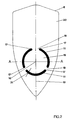
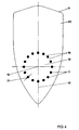
- FIGS to 4 Different arrangements of the openings 11, which in connection with the means of the piezoelectric element 14 made atomization of liquid in the soleplate 6 are suitable, are further shown in Figures 2, 3 and 4.
- the arrangement of the openings 11 is essentially symmetrical the center line 10 and lying on a circle, the center of which is shown in FIGS to 4 is designated by the reference numeral 16.
- the number of breakthroughs 11 in accordance with the embodiment in FIG. 2 is three, these individual openings being constructed as curved elongated holes, each occupying a segment of a circle with respect to the center 16 of approximately 100 °.
- the ends 17 of the respective openings 11 are spaced apart from one another, that in between a web 18 remains, the sole area 19, which of the Breakthroughs 11 is enclosed with the further sole area or sole surface 20 connect.
- FIG. 1 In a third embodiment of the openings 11, which is shown in FIG A total of six openings are provided, which in turn are symmetrical to the center line 10 run.
- Figures 1 and 2 it is contrary to the explanations of Figures 1 and 2 to rectilinear slots that form an imaginary circle with the Center point, which is designated by the reference numeral 16, evenly distributed tangent.
- FIG. 4 shows an arrangement of the openings 11, however is not to be regarded as preferred, in the form of circular holes, namely a total of 16 holes arranged on a circle with the center point 16 are.
- the diameter of the circle on which the respective openings 11 are centered are aligned or tangent to it with their center line, is about 60 to 65 mm.
- the width of the openings in each case, designated by the reference symbol 21, i.e. the dimension transverse to the longitudinal extent of the individual elongated holes is approximately 5 mm; this small width ensures that no parts of the ironing material, such as for example buttons, can get caught in these openings when ironing.
- this dimension of the openings is sufficient to make a necessary one To achieve liquid discharge.
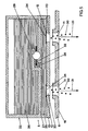
- a tank system 22 which is the front housing section 5 can act, arranged.
- This tank system 22 comprises a carrier plate, which with the carrier part 13 in Figure 1 is comparable, which in turn comprises openings 23 which correspond in size to the openings 11 in the soleplate 6.
- the membrane plate 12 On The top of this carrier part 13 is the membrane plate 12, as also shown in FIG. 1 is shown, which in turn has a plurality of atomizing openings 24.
- This membrane plate 12 is relatively thin, so that it, at the edge of the support part 13 held, in the area of the openings 23 with a corresponding piezoelectric Excitation can swing.
- a space 25 which contains a part of the liquid with which to iron To be moistened well.
- Another liquid reservoir 26 that the Main liquid reservoir in the iron is above room 25, separated from the room 25 by a partition 27.
- the space 25 and the main reservoir 26 are connected to one another via a connecting channel 28 connected.
- a pump 29 or in the connecting channel 28 another suitable facility may be provided.
- this promotes liquid from the main reservoir 26 in all operating states of the iron to the room 25, indicated by the arrow 32, so that the room 25 preferably completely filled with liquid.
- the liquid droplets 30 are immediately in the Area of the soleplate 6, i.e. in the openings 11 of the soleplate or Openings 23 are created in the carrier part 13.
- the membrane plate 12 becomes as shown in FIG is seen through a piezo-electric element 14 which is suitably above the membrane plate 12 is arranged to vibrate to release the liquid droplets 30 in defined quantities.
- a fine drizzle of liquid to achieve the diameter of the individual atomizing openings 24 are in the range from 30 to 100 ⁇ m, with opening widths between 45 up to 60 ⁇ m are preferable.
- the Number of these atomizing openings selected so that a maximum of 8 g / minute of liquid is released from the liquid container 25 onto the ironing material.
Landscapes
- Engineering & Computer Science (AREA)
- Textile Engineering (AREA)
- Irons (AREA)
Claims (16)
- Fer à repasser électrique avec une semelle qui présente une pointe de semelle, et avec au moins un perçage, symétrique à une ligne médiane qui, en partant de la pointe, sépare la semelle au milieu, disposé au voisinage de la pointe de semelle dans la semelle, pour le passage d'un liquide stocké dans un système formant réservoir de liquide pour humidifier un article à repasser, où le liquide sort du perçage sous la forme de gouttelettes de liquide, produites au moyen d'une installation de pulvérisation excitée d'une manière piézoélectrique au-dessus de la semelle, caractérisé en ce que l'installation de pulvérisation (12, 13, 14 ; 29) comporte au moins une plaque de membrane mince (12) excitée d'une manière piézoélectrique qui présente une multitude d'ouvertures de pulvérisation (24) associées au perçage respectif (11) de la semelle (6), qui ont respectivement une largeur d'ouverture moyenne de 30 à 100 µm, où le nombre des ouvertures de pulvérisation (24) est sélectionné de façon que par la semelle (6) soit assurée une émission de liquide jusqu'à environ 8 g/minute au maximum, et où les perçages (11), quelle que soit la longueur, ont une largeur de 10 mm au maximum.
- Fer à repasser électrique selon la revendication 1, caractérisé en ce que les perçages (11) sont répartis autour d'un centre (16) sur la ligne médiane (10) de la semelle (6).
- Fer à repasser électrique selon la revendication 1, caractérisé en ce que des perçages avoisinants (11) sont espacés les uns des autres par des nervures (18).
- Fer à repasser électrique selon la revendication 3, caractérisé en ce que les perçages (11) sont disposés en forme de cercle.
- Fer à repasser électrique selon la revendication 4, caractérisé en ce que les perçages (11) sont réalisés respectivement sous forme de trou oblong ou de tronçon de cercle.
- Fer à repasser électrique selon la revendication 5, caractérisé en ce que les perçages (11) dans la semelle (6) sont au maximum au nombre de six, de préférence au nombre de trois ou de quatre.
- Fer à repasser électrique selon la revendication 6, caractérisé en ce que trois perçages (11) sont prévus qui occupent un tronçon radial respectivement jusqu'à 100° en regardant depuis le centre (16).
- Fer à repasser électrique selon la revendication 6 ou la revendication 7, caractérisé en ce qu'il est associé à la zone (19) de la semelle (6) entourée des perçages (11) un élément chauffant (8).
- Fer à repasser électrique selon la revendication 1, caractérisé en ce que pendant le repassage, une dépression est maintenue au moins dans une zone au-dessus de la plaque de membrane (12) recouverte de liquide.
- Fer à repasser électrique selon la revendication 1, caractérisé en ce que la largeur d'ouverture des ouvertures de pulvérisation (24) est de 45 à 60 µm.
- Fer à repasser électrique selon la revendication 4, caractérisé en ce que les perçages (11) sont disposés sur un cercle d'un diamètre de 50 à 100 mm, de préférence d'environ 70 mm.
- Fer à repasser électrique selon la revendication 1, caractérisé en ce que les perçages (11) ont une largeur maximale (21) de 6 mm.
- Fer à repasser électrique selon la revendication 1, caractérisé en ce que pendant le repassage, la ou les plaques de membrane (12) limite(nt) la réserve de liquide (25) comme partie de paroi.
- Fer à repasser électrique selon la revendication 1, caractérisé en ce que le nombre des ouvertures de pulvérisation (24) est compris entre 70 et 100.
- Fer à repasser électrique selon la revendication 1, caractérisé en ce que l'amenée du liquide vers, et l'évacuation du liquide depuis la plaque de membrane (12) sont amortis.
- Fer à repasser électrique selon la revendication 1, caractérisé en ce que les perçages (11) sont arrondis dans la zone de transition vers la semelle (19, 20).
Applications Claiming Priority (3)
| Application Number | Priority Date | Filing Date | Title |
|---|---|---|---|
| DE19634276 | 1996-08-24 | ||
| DE19634276 | 1996-08-24 | ||
| PCT/EP1997/004518 WO1998007919A1 (fr) | 1996-08-24 | 1997-08-20 | Fer a repasser electrique a semelle |
Publications (2)
| Publication Number | Publication Date |
|---|---|
| EP0923656A1 EP0923656A1 (fr) | 1999-06-23 |
| EP0923656B1 true EP0923656B1 (fr) | 2002-10-09 |
Family
ID=7803606
Family Applications (1)
| Application Number | Title | Priority Date | Filing Date |
|---|---|---|---|
| EP97918989A Expired - Lifetime EP0923656B1 (fr) | 1996-08-24 | 1997-08-20 | Fer a repasser electrique a semelle |
Country Status (6)
| Country | Link |
|---|---|
| US (1) | US6035563A (fr) |
| EP (1) | EP0923656B1 (fr) |
| DE (2) | DE19735214C2 (fr) |
| ES (1) | ES2185007T3 (fr) |
| RU (1) | RU2149935C1 (fr) |
| WO (1) | WO1998007919A1 (fr) |
Cited By (1)
| Publication number | Priority date | Publication date | Assignee | Title |
|---|---|---|---|---|
| USD743662S1 (en) | 2014-09-26 | 2015-11-17 | Morphy Richards Limited | Iron |
Families Citing this family (32)
| Publication number | Priority date | Publication date | Assignee | Title |
|---|---|---|---|---|
| DE29819061U1 (de) | 1998-10-26 | 1999-05-12 | Wagner, Heidemarie, 76327 Pfinztal | Mittel zur Nachparfümierung maschinengetrockneter Wäsche |
| FR2804137B1 (fr) * | 2000-01-20 | 2003-07-04 | Moulinex Sa | Fer a repasser comportant une pompe a melange d'eau et d'adjuvant textile |
| US6785989B2 (en) * | 2000-03-31 | 2004-09-07 | The Procter & Gamble Company | Methods and apparatus for removal of wrinkles from fabrics |
| AU8765001A (en) * | 2000-07-28 | 2002-02-13 | Fry Alan John | Ironing aid composition |
| DE10050344A1 (de) * | 2000-10-11 | 2002-05-02 | Bsh Bosch Siemens Hausgeraete | Kaltnebel-Bügeleisen |
| FR2816963B1 (fr) * | 2000-11-22 | 2003-01-24 | Rowenta Werke Gmbh | Fer a repasser sans cordon avec atomiseur d'eau piezo-electrique |
| EP1214986A1 (fr) | 2000-12-13 | 2002-06-19 | Siemens Aktiengesellschaft | Atomiseur à ultrasons |
| FR2821369B1 (fr) * | 2001-02-27 | 2003-09-05 | Rowenta Werke Gmbh | Fer a repasser a vapeur pulsee |
| US20030136035A1 (en) * | 2002-01-11 | 2003-07-24 | David Lehrman | Fragrance emitting ironing board cover |
| CN100507139C (zh) * | 2002-07-24 | 2009-07-01 | 皇家飞利浦电子股份有限公司 | 具有织物接触检测仪的熨斗 |
| AU2003255958A1 (en) * | 2002-08-26 | 2004-03-11 | Koninklijke Philips Electronics N.V. | Electric steaming device |
| DE10260156A1 (de) * | 2002-12-20 | 2004-07-01 | BSH Bosch und Siemens Hausgeräte GmbH | Wäschetrockner und Verwendung eines Ultraschallzerstäubers |
| US20050028408A1 (en) * | 2003-08-06 | 2005-02-10 | Tobias Andrew J. | Convertible iron/steamer |
| US7062869B1 (en) | 2003-11-19 | 2006-06-20 | Lucy Pilcher | Quick starch spray iron |
| EP1702098B1 (fr) * | 2003-12-16 | 2011-03-09 | Koninklijke Philips Electronics N.V. | Dispositif de repassage a vapeur |
| JP4762975B2 (ja) * | 2004-03-29 | 2011-08-31 | コーニンクレッカ フィリップス エレクトロニクス エヌ ヴィ | 蒸気流において渦を得る渦発生手段を有する蒸気アイロン装置 |
| US20070090073A1 (en) * | 2005-10-26 | 2007-04-26 | The Stanley Works | System for displaying a sample of a product |
| DE102005059505A1 (de) * | 2005-12-06 | 2007-06-14 | E.G.O. Elektro-Gerätebau GmbH | Haushaltsgerät und Verfahren zum Betrieb eines Haushaltsgeräts |
| RU2314373C1 (ru) * | 2006-04-26 | 2008-01-10 | Сергей Александрович Аникин | Оснастка для ручного утюга для предотвращения замятий |
| US7681342B2 (en) * | 2006-05-05 | 2010-03-23 | Lung Wai Choi | Induction ironing apparatus and method |
| US7997018B1 (en) | 2007-10-05 | 2011-08-16 | Lenford, Inc. | Devices and methods of facilitating cooking and ironing using vibration pulses |
| ES2327889B1 (es) * | 2007-12-21 | 2010-09-07 | Bsh Krainel, S.A. | Dispositivo de rociado para una plancha. |
| US8720325B2 (en) | 2010-04-29 | 2014-05-13 | Whirlpool Corporation | Food processor with a lockable adjustable blade assembly |
| US10449685B2 (en) | 2010-04-29 | 2019-10-22 | Whirlpool Corporation | Food processor with adjustable blade assembly |
| EP2418318A1 (fr) | 2010-08-12 | 2012-02-15 | Koninklijke Philips Electronics N.V. | Fer à repasser avec hydratation de vêtement à phase liquide |
| EP2418317A1 (fr) * | 2010-08-12 | 2012-02-15 | Koninklijke Philips Electronics N.V. | Hydratation de vêtement à phase liquide comportant du fer via une plaque |
| GB2485553B (en) | 2010-11-17 | 2014-01-22 | Richards Morphy N I Ltd | Electric iron with nozzle for water mist |
| GB2504896B (en) * | 2011-04-20 | 2016-05-18 | Notable Creations Inc | Apparatus for removing wrinkles from fabric |
| WO2015160890A1 (fr) * | 2014-04-16 | 2015-10-22 | Spectrum Brands, Inc. | Appareil de cuisson utilisant un élément chauffant à film mince |
| US10085599B2 (en) | 2014-12-19 | 2018-10-02 | Whirlpool Corporation | Multi-cook and food processing prep product |
| HK1200643A2 (en) * | 2015-03-13 | 2015-08-07 | 蔡龙威 | Electric steam iron with uv steam sterilization function |
| TR201722472A2 (tr) * | 2017-12-28 | 2019-07-22 | Arcelik As | Bi̇r ütü |
Family Cites Families (13)
| Publication number | Priority date | Publication date | Assignee | Title |
|---|---|---|---|---|
| DE214404C (fr) * | ||||
| US1859167A (en) * | 1931-09-04 | 1932-05-17 | Prenzel Adam Henry | Laundry iron |
| US2802288A (en) * | 1953-02-13 | 1957-08-13 | Gen Electric | Steam irons |
| BE558745A (fr) * | 1956-07-25 | |||
| US3238650A (en) * | 1964-10-15 | 1966-03-08 | Robert Warwick W | Sole plate for laundering irons |
| US3534488A (en) * | 1968-08-07 | 1970-10-20 | Peter D Hardwick | Pressing iron having starch dispenser |
| US4545561A (en) * | 1982-07-30 | 1985-10-08 | Mcdonnell Douglas Corporation | Piezoelectric valve operator |
| US4993175A (en) * | 1988-08-12 | 1991-02-19 | Black & Decker, Inc. | Soleplate steam slot arrangement |
| SU1673668A1 (ru) * | 1989-04-06 | 1991-08-30 | Орловский научно-исследовательский институт легкого машиностроения | Утюг |
| DE4310273C2 (de) * | 1993-03-30 | 1995-03-23 | Rowenta Werke Gmbh | Elektrisches Bügeleisen |
| US5787614A (en) * | 1993-03-30 | 1998-08-04 | Rowenta-Werke Gmbh | Electric steam iron with aerosol sprayer |
| JPH0747197A (ja) * | 1993-08-04 | 1995-02-21 | Matsushita Electric Ind Co Ltd | 噴霧式アイロン |
| FR2740787B1 (fr) * | 1995-11-03 | 1999-06-11 | Moulinex Sa | Fer a repasser a vapeur |
-
1997
- 1997-08-14 DE DE19735214A patent/DE19735214C2/de not_active Expired - Fee Related
- 1997-08-20 DE DE59708450T patent/DE59708450D1/de not_active Expired - Lifetime
- 1997-08-20 WO PCT/EP1997/004518 patent/WO1998007919A1/fr not_active Ceased
- 1997-08-20 RU RU99106582A patent/RU2149935C1/ru active
- 1997-08-20 ES ES97918989T patent/ES2185007T3/es not_active Expired - Lifetime
- 1997-08-20 US US09/242,794 patent/US6035563A/en not_active Expired - Lifetime
- 1997-08-20 EP EP97918989A patent/EP0923656B1/fr not_active Expired - Lifetime
Cited By (1)
| Publication number | Priority date | Publication date | Assignee | Title |
|---|---|---|---|---|
| USD743662S1 (en) | 2014-09-26 | 2015-11-17 | Morphy Richards Limited | Iron |
Also Published As
| Publication number | Publication date |
|---|---|
| EP0923656A1 (fr) | 1999-06-23 |
| DE19735214A1 (de) | 1998-02-26 |
| US6035563A (en) | 2000-03-14 |
| WO1998007919A1 (fr) | 1998-02-26 |
| RU2149935C1 (ru) | 2000-05-27 |
| DE19735214C2 (de) | 1998-07-09 |
| ES2185007T3 (es) | 2003-04-16 |
| DE59708450D1 (de) | 2002-11-14 |
Similar Documents
| Publication | Publication Date | Title |
|---|---|---|
| DE19735214C2 (de) | Elektrisches Bügeleisen mit einer Bügelsohle | |
| EP0908551B1 (fr) | Fer à repasser à vapeur avec sortie de vapeur sur le devant et le côté du fer | |
| DE69417697T2 (de) | Vorrichtung zur Behandlung von Haaren mit Dampf | |
| DE69216562T2 (de) | Elektrisches Dampfbügeleisen | |
| DE60212880T2 (de) | Nebel-bügeleisen | |
| DE2510802A1 (de) | Heizelement fuer elektrisch beheizte fluessigkeitsverdampfer | |
| WO1996006970A1 (fr) | Fer a repasser a vapeur | |
| DE2701047B2 (de) | Elektro-Dampfbügeleisen | |
| EP1959049B1 (fr) | Finisseur à tunnel | |
| DE2145181B2 (de) | Vorrichtung zum aufspruehen von fluessigkeiten auf lockenwickler | |
| DE10050344A1 (de) | Kaltnebel-Bügeleisen | |
| DE4310273C2 (de) | Elektrisches Bügeleisen | |
| DE2356062B2 (de) | Elektrisches dampfbuegeleisen | |
| EP0377803B1 (fr) | Fer à repasser à vapeur électrique | |
| DE1635123B2 (de) | Vorrichtung zum kontinuierlichen waermebehandeln, wie trocknen, daempfen oder farbstoff-fixieren von bahnfoermigen guetern | |
| DE2132844C3 (de) | Trockenvorrichtung für eine Webmaschine | |
| DE2556487C3 (de) | Vorrichtung zum kontinuierlichen Imprägnieren von Textilien in Strangform | |
| WO1994026966A1 (fr) | Dispositif d'application de liquides sur des textiles et similaires, notamment appareil a repasser | |
| EP4528018B1 (fr) | Générateur de vapeur portable pour le traitement à la vapeur d'un produit à vaporiser | |
| DE102018222295A1 (de) | Funktionselement für einen handhaltbaren Dampferzeuger zur Behandlung von Kleidungsstücken und handhaltbarer Dampferzeuger | |
| DE1016226B (de) | Verfahren zum Staerken od. dgl. von Waesche und Dampfbuegeleisen zur Ausuebung dieses Verfahrens | |
| CH557915A (de) | Gas-sengbrenner fuer gewebebahnen. | |
| DE4032743A1 (de) | Waeschetrockner | |
| DE650865C (de) | Verfahren zum Entwaessern und Trocknen von Rohstoffbahnen oder -bogen, wie Cellulose, Holzstoff o. dgl. | |
| DE1295353B (de) | Vorrichtung zum Befeuchten von Papierbahnen od. dgl. |
Legal Events
| Date | Code | Title | Description |
|---|---|---|---|
| PUAI | Public reference made under article 153(3) epc to a published international application that has entered the european phase |
Free format text: ORIGINAL CODE: 0009012 |
|
| 17P | Request for examination filed |
Effective date: 19990127 |
|
| AK | Designated contracting states |
Kind code of ref document: A1 Designated state(s): DE ES FR GB IT PT |
|
| GRAG | Despatch of communication of intention to grant |
Free format text: ORIGINAL CODE: EPIDOS AGRA |
|
| GRAG | Despatch of communication of intention to grant |
Free format text: ORIGINAL CODE: EPIDOS AGRA |
|
| GRAH | Despatch of communication of intention to grant a patent |
Free format text: ORIGINAL CODE: EPIDOS IGRA |
|
| 17Q | First examination report despatched |
Effective date: 20011114 |
|
| GRAH | Despatch of communication of intention to grant a patent |
Free format text: ORIGINAL CODE: EPIDOS IGRA |
|
| GRAA | (expected) grant |
Free format text: ORIGINAL CODE: 0009210 |
|
| AK | Designated contracting states |
Kind code of ref document: B1 Designated state(s): DE ES FR GB IT PT |
|
| REG | Reference to a national code |
Ref country code: GB Ref legal event code: FG4D Free format text: NOT ENGLISH |
|
| REF | Corresponds to: |
Ref document number: 59708450 Country of ref document: DE Date of ref document: 20021114 |
|
| GBT | Gb: translation of ep patent filed (gb section 77(6)(a)/1977) |
Effective date: 20021031 |
|
| PG25 | Lapsed in a contracting state [announced via postgrant information from national office to epo] |
Ref country code: PT Free format text: LAPSE BECAUSE OF FAILURE TO SUBMIT A TRANSLATION OF THE DESCRIPTION OR TO PAY THE FEE WITHIN THE PRESCRIBED TIME-LIMIT Effective date: 20030109 |
|
| REG | Reference to a national code |
Ref country code: ES Ref legal event code: FG2A Ref document number: 2185007 Country of ref document: ES Kind code of ref document: T3 |
|
| ET | Fr: translation filed | ||
| PLBE | No opposition filed within time limit |
Free format text: ORIGINAL CODE: 0009261 |
|
| STAA | Information on the status of an ep patent application or granted ep patent |
Free format text: STATUS: NO OPPOSITION FILED WITHIN TIME LIMIT |
|
| 26N | No opposition filed |
Effective date: 20030710 |
|
| PGFP | Annual fee paid to national office [announced via postgrant information from national office to epo] |
Ref country code: GB Payment date: 20120824 Year of fee payment: 16 |
|
| PGFP | Annual fee paid to national office [announced via postgrant information from national office to epo] |
Ref country code: DE Payment date: 20120808 Year of fee payment: 16 Ref country code: IT Payment date: 20120821 Year of fee payment: 16 Ref country code: FR Payment date: 20120919 Year of fee payment: 16 Ref country code: ES Payment date: 20120828 Year of fee payment: 16 |
|
| GBPC | Gb: european patent ceased through non-payment of renewal fee |
Effective date: 20130820 |
|
| PG25 | Lapsed in a contracting state [announced via postgrant information from national office to epo] |
Ref country code: DE Free format text: LAPSE BECAUSE OF NON-PAYMENT OF DUE FEES Effective date: 20140301 |
|
| REG | Reference to a national code |
Ref country code: DE Ref legal event code: R119 Ref document number: 59708450 Country of ref document: DE Effective date: 20140301 |
|
| REG | Reference to a national code |
Ref country code: FR Ref legal event code: ST Effective date: 20140430 |
|
| PG25 | Lapsed in a contracting state [announced via postgrant information from national office to epo] |
Ref country code: IT Free format text: LAPSE BECAUSE OF NON-PAYMENT OF DUE FEES Effective date: 20130820 |
|
| PG25 | Lapsed in a contracting state [announced via postgrant information from national office to epo] |
Ref country code: GB Free format text: LAPSE BECAUSE OF NON-PAYMENT OF DUE FEES Effective date: 20130820 |
|
| PG25 | Lapsed in a contracting state [announced via postgrant information from national office to epo] |
Ref country code: FR Free format text: LAPSE BECAUSE OF NON-PAYMENT OF DUE FEES Effective date: 20130902 |
|
| REG | Reference to a national code |
Ref country code: ES Ref legal event code: FD2A Effective date: 20140909 |
|
| PG25 | Lapsed in a contracting state [announced via postgrant information from national office to epo] |
Ref country code: ES Free format text: LAPSE BECAUSE OF NON-PAYMENT OF DUE FEES Effective date: 20130821 |