EP0922419B1 - Rückenlehne - Google Patents
Rückenlehne Download PDFInfo
- Publication number
- EP0922419B1 EP0922419B1 EP98119372A EP98119372A EP0922419B1 EP 0922419 B1 EP0922419 B1 EP 0922419B1 EP 98119372 A EP98119372 A EP 98119372A EP 98119372 A EP98119372 A EP 98119372A EP 0922419 B1 EP0922419 B1 EP 0922419B1
- Authority
- EP
- European Patent Office
- Prior art keywords
- frame
- cover
- backrest
- backrest according
- transverse
- Prior art date
- Legal status (The legal status is an assumption and is not a legal conclusion. Google has not performed a legal analysis and makes no representation as to the accuracy of the status listed.)
- Expired - Lifetime
Links
Images





Classifications
-
- A—HUMAN NECESSITIES
- A47—FURNITURE; DOMESTIC ARTICLES OR APPLIANCES; COFFEE MILLS; SPICE MILLS; SUCTION CLEANERS IN GENERAL
- A47C—CHAIRS; SOFAS; BEDS
- A47C5/00—Chairs of special materials
- A47C5/04—Metal chairs, e.g. tubular
- A47C5/06—Special adaptation of seat upholstery or fabric for attachment to tubular chairs
-
- A—HUMAN NECESSITIES
- A47—FURNITURE; DOMESTIC ARTICLES OR APPLIANCES; COFFEE MILLS; SPICE MILLS; SUCTION CLEANERS IN GENERAL
- A47C—CHAIRS; SOFAS; BEDS
- A47C7/00—Parts, details, or accessories of chairs or stools
- A47C7/36—Supports for the head or the back
- A47C7/40—Supports for the head or the back for the back
-
- A—HUMAN NECESSITIES
- A47—FURNITURE; DOMESTIC ARTICLES OR APPLIANCES; COFFEE MILLS; SPICE MILLS; SUCTION CLEANERS IN GENERAL
- A47C—CHAIRS; SOFAS; BEDS
- A47C7/00—Parts, details, or accessories of chairs or stools
- A47C7/36—Supports for the head or the back
- A47C7/40—Supports for the head or the back for the back
- A47C7/42—Supports for the head or the back for the back of detachable or loose type
Definitions
- the invention relates to a backrest, in particular for an office chair, according to the preamble of the first claim.
- Backrests especially for chairs used in the office or commercial area in addition to ergonomic, aesthetic and economic aspects Take into account. From an ergonomic point of view, alongside a kinematic coupling the seat of the chair in particular also the back-shaped and flexible Storage of the backrest a role.
- European Patent EP 0 308 538 in this regard, a movably mounted backrest is specified, which is designed such that supporting both sagittal and torsional and transverse movements of the back gives way.
- This backrest comprises a fixed cushion shell into which a cushion is inserted is.
- the so-called membrane technology is also common. With this technique, a reference to a frame is stretched.
- the invention therefore achieves the object of specifying a backrest in membrane technology, which is easy and inexpensive to manufacture, which is also aesthetic and ergonomic Fully meets requirements and has a long service life.
- This The object is solved by the features of the first claim.
- the essence of the invention is therefore that the frame of the backrest is articulated and open at the bottom.
- the frame is thus rotatable to a certain extent. Therefore, the frame can be easily done refer to the cover.
- the frame can then be inserted by inserting a crossbar be brought into the final form. This will stretch the cover in the transverse direction. By pulling the cover in the longitudinal direction towards the crossbar, a three-dimensional is created Formation of the backrest surface, that in sagittal or vertical and horizontal Level meets ergonomic requirements.
- the frame faces the one opposite the crossbar Corners joints on.
- the joints can be angled to run to withdraw the reference.
- Another preferred exemplary embodiment is characterized in that that the crossbar is equipped with a groove in which a sewn-in profile of the Reference can be inserted. This represents an extremely simple way of attaching the cover on the crossbar and enables a defined tension of the cover in Longitudinal fastening without protruding fringes or annoying stitches. Further Embodiments result from the corresponding dependent claims.
- the frame 1 shows a frame 1 according to the invention and an insertable crossbar 2.
- the frame 1 is open at the bottom and consists essentially of bent tubes. He is therefore very easy to manufacture.
- the tubes are open at the bottom and for receiving appropriate Prepared pin 3 of the crossbar 2.
- the frame has 1 joints 4 at corners.
- the frame points depending on the one you want Backrest shape, for example, essentially the shape of a square "U” on die Leg 5 of the "U” can be pivoted with the help of the joints 4 relative to the cross connection 6 become.
- the frame 1 takes its final shape only by inserting the crossbar 2 a. In order to fix this position, there are 5 fastening tabs 7 on the legs provided with a correspondingly shaped mounting plate 8 of the crossbar screwed or mechanically connected in some other way.
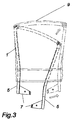
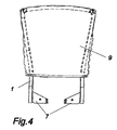
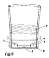
- FIGS. 3 to 7 different stations are shown when covering the frame 1 with a cover 9.
- the cover 9 is bag-shaped and can either be sewn or otherwise Joining at least two parts or by weaving a one-piece Sacks are formed.
- the shape of the cover 9 is essentially due to the design of the chair and given by ergonomic requirements.
- the cover 9 is in this position in the longitudinal and transverse directions not yet excited.
- the tension in the transverse direction is achieved in that, as in Figure 5 is shown, the legs 5 are pressed apart until the crossbar 2 in the provided openings of the frame 1 can be inserted ( Figure 6). Subsequently the cover 9 is stretched against the crossbar to build up a longitudinal tension (FIG 7).
- the cover 9 has at its opening Sewn-in profiles 10, which are inserted into a groove 11 provided in the crossbar 2 can be (piping technique).
- Figure 8 shows this process in detail.
- the profiles 10 are in arranged on both sides of the sewn-in tunnel 12.
- Figure 9 shows the frame 1 from the side. It can clearly be seen how the joints 4 are angled slightly are and the frame 1 forms a light, stepped arc. After stringing of the frame 1 with a cover, is formed in relation to the transverse and longitudinal tension a three-dimensional shape, that of an ergonomically favorable, back-supporting Area corresponds. For the user, the backrest according to the invention is made of this Reason very comfortable. The ergonomic support is particularly noteworthy thanks to the three-dimensional shape of the reference surface and the good ventilation of the backrest. If desired, an additional cushion can be attached to the cover.
- the backrest according to the invention is summarized by a simple and cost-effective production and excellent ergonomic and aesthetic properties out.
Landscapes
- Chair Legs, Seat Parts, And Backrests (AREA)
- Pharmaceuticals Containing Other Organic And Inorganic Compounds (AREA)
- Purses, Travelling Bags, Baskets, Or Suitcases (AREA)
Description
- Fig. 1
- Einen erfindungsgemäßen Rahmen und ein dazu passender Querbügel;
- Fig. 2
- Den erfindungsgemäßen Rahmen in verdrehtem Zustand;
- Fig. 3-7
- Verschiedene Stationen beim Beziehen des Rahmens mit einem Bezug;
- Fig. 8
- Eine Detailansicht des Querbügels;
- Fig. 9
- Einen erfindungsgemäßen Rahmen von der Seite.
- 1
- Rahmen
- 2
- Querbügel
- 3
- Zapfen
- 4
- Gelenk
- 5
- Schenkel
- 6
- Querverbindung
- 7
- Befestigungslasche
- 8
- Befestigungsplatte
- 9
- Bezug
- 10
- Profil
- 11
- Nut
- 12
- Tunnel
Claims (8)
- Rückenlehne, insbesondere geeignet für einen Bürostuhl, umfassend einen Rahmen (1), an welchem ein sackartiger Bezug (9) befestigt ist, dadurch gekennzeichnet, daß der Rahmen (1) gelenkig aufgebaut ist und die Rückenlehne einen in den Rahmen (1) einsteckbaren Querbügel (2) aufweist, wobei der Rahmen (1) durch gelenkiges Verdrehen in den unten offenen Bezug (9) einführbar ist, und der Bezug (9) durch Einstecken des Querbügels (2) in den Rahmen (1) in Querrichtung und durch Befestigen des Bezuges (9) am Querbügel (2) in Längsrichtung spannbar ist.
- Rückenlehne nach Anspruch 1, dadurch gekennzeichnet, daß der Rahmen (1) im wesentlichen eine eckige U-Form aufweist und an den dem Querbügel (2) gegenüberliegenden Ekken Gelenke (4) aufweist.
- Rückenlehne nach Anspruch 2, dadurch gekennzeichnet, daß die Gelenke (4) abgewinkelt und/oder abgerundet sind.
- Rückenlehne nach Anspruch 3, dadurch gekennzeichnet, daß die Gelenke (4) aus einem Leichtmetall oder Kunststoff bestehen.
- Rückenlehne nach einem der vorstehenden Ansprüche, dadurch gekennzeichnet, daß der Querbügel (2) mindestens eine Nut (11) aufweist, in welche beiderseits in den Bezug (9) gesteckte Profile (10) eingeführt werden können.
- Rückenlehne nach Anspruch 4, dadurch gekennzeichnet, daß der Bezug (9) im Bereich der Öffnung beiderseits Tunnels (12) aufweist, in die die Profile (10) einsteckbar sind.
- Rückenlehne nach einem der Ansprüche 1 bis 6, dadurch gekennzeichnet, daß der Querbügel für die mechanische Anlenkung mit einer Sitzfläche ausgebildet ist.
- Rückenlehne nach einem der Ansprüche 1 bis 7, dadurch gekennzeichnet, daß auf dem Bezug (9) ein Polster befestigt ist.
Applications Claiming Priority (2)
| Application Number | Priority Date | Filing Date | Title |
|---|---|---|---|
| DE19754817A DE19754817A1 (de) | 1997-12-10 | 1997-12-10 | Rückenlehne |
| DE19754817 | 1997-12-10 |
Publications (3)
| Publication Number | Publication Date |
|---|---|
| EP0922419A2 EP0922419A2 (de) | 1999-06-16 |
| EP0922419A3 EP0922419A3 (de) | 2001-01-31 |
| EP0922419B1 true EP0922419B1 (de) | 2003-09-24 |
Family
ID=7851398
Family Applications (1)
| Application Number | Title | Priority Date | Filing Date |
|---|---|---|---|
| EP98119372A Expired - Lifetime EP0922419B1 (de) | 1997-12-10 | 1998-10-14 | Rückenlehne |
Country Status (5)
| Country | Link |
|---|---|
| US (1) | US6050646A (de) |
| EP (1) | EP0922419B1 (de) |
| AT (1) | ATE250370T1 (de) |
| DE (2) | DE19754817A1 (de) |
| ES (1) | ES2206806T3 (de) |
Cited By (1)
| Publication number | Priority date | Publication date | Assignee | Title |
|---|---|---|---|---|
| JP2009112359A (ja) * | 2007-11-02 | 2009-05-28 | Okamura Corp | 椅子の背凭れ |
Families Citing this family (82)
| Publication number | Priority date | Publication date | Assignee | Title |
|---|---|---|---|---|
| US6220661B1 (en) * | 1999-04-19 | 2001-04-24 | Steelcase Development Inc. | Chair back and method of assembly |
| DE10018291A1 (de) | 2000-04-13 | 2001-10-25 | Sieghard Schiller Gmbh & Co Kg | Vorrichtung zum Beschichten von Werkstücken |
| DE10032928A1 (de) * | 2000-07-06 | 2002-01-17 | Interstuhl Bueromoebel Gmbh | Rückenlehne eines Stuhls |
| FR2812596B1 (fr) * | 2000-08-04 | 2002-10-31 | Faure Bertrand Equipements Sa | Dossier de siege de vehicule automobile |
| DE10048666A1 (de) * | 2000-09-30 | 2002-04-11 | Dauphin Friedrich W Gmbh | Rückenlehne für einen Stuhl |
| DE10050151C1 (de) * | 2000-10-11 | 2002-03-07 | Mauser Office Gmbh | Rückenlehnenelement für ein Sitzmöbel |
| US6572190B2 (en) | 2001-06-15 | 2003-06-03 | Hon Technology Inc. | Lumbar support for a chair |
| DE10148645A1 (de) | 2001-10-02 | 2003-04-10 | Dauphin Friedrich W Gmbh | Rückenlehne für einen Stuhl |
| US6886890B2 (en) * | 2002-06-07 | 2005-05-03 | David L. Rowland | Panel |
| JP4159316B2 (ja) * | 2002-07-17 | 2008-10-01 | タカノ株式会社 | 背凭れの取付構造 |
| US7055911B2 (en) * | 2003-05-08 | 2006-06-06 | Haworth, Inc. | Mesh chair |
| US20040262975A1 (en) * | 2003-06-27 | 2004-12-30 | Tung-Hua Su | Backrest assembly |
| ATE489874T1 (de) * | 2004-05-13 | 2010-12-15 | Humanscale Corp | Stuhl mit säulenförmigem fuss mit membranplatten |
| US7025424B2 (en) * | 2004-06-07 | 2006-04-11 | Allseating Corporation | Chair back for a chair |
| JP4652767B2 (ja) * | 2004-10-13 | 2011-03-16 | 株式会社岡村製作所 | 椅子の背凭れ等における張材の張設構造 |
| US20060080817A1 (en) * | 2004-10-19 | 2006-04-20 | Scott Klinker | Method of forming a furniture article using heat-shrinkable material, and article formed therefrom |
| US7422287B2 (en) * | 2005-03-08 | 2008-09-09 | Steelcase Inc. | Seating with shape-changing back support frame |
| USD623449S1 (en) | 2005-05-13 | 2010-09-14 | Humanscale Corporation | Mesh backrest for a chair |
| USD549478S1 (en) | 2005-06-07 | 2007-08-28 | Steelcase Development Corporation | Chair |
| US7416251B2 (en) * | 2005-06-10 | 2008-08-26 | Global Total Office | Chair |
| US8061775B2 (en) | 2005-06-20 | 2011-11-22 | Humanscale Corporation | Seating apparatus with reclining movement |
| JP5002835B2 (ja) | 2005-10-27 | 2012-08-15 | コクヨ株式会社 | 部材の接続構造 |
| JP4719905B2 (ja) * | 2005-10-27 | 2011-07-06 | コクヨ株式会社 | 椅子 |
| JP4945781B2 (ja) | 2005-11-11 | 2012-06-06 | コクヨ株式会社 | 椅子 |
| JP4747311B2 (ja) * | 2005-11-11 | 2011-08-17 | コクヨ株式会社 | 椅子 |
| JP5031288B2 (ja) | 2006-07-24 | 2012-09-19 | 株式会社岡村製作所 | 椅子の背凭れ装置 |
| US7540568B2 (en) * | 2007-08-20 | 2009-06-02 | Natura Design Inc. | Three-dimensional unfilled furniture |
| US7926879B2 (en) | 2007-09-20 | 2011-04-19 | Herman Miller, Inc. | Load support structure |
| CN101835408B (zh) | 2007-11-02 | 2014-03-05 | 株式会社冈村制作所 | 椅子的椅背及其安装装置 |
| GB0815410D0 (en) * | 2008-08-22 | 2008-10-01 | Mountway Ltd | Improvements in and relating to adjustable seats |
| WO2010045745A1 (de) * | 2008-10-21 | 2010-04-29 | Vitra Patente Ag | Rückenlehne für einen stuhl |
| EP2359717B1 (de) | 2008-10-29 | 2014-11-26 | Okamura Corporation | Rückenlehne für einen stuhl |
| US8033598B2 (en) | 2008-12-24 | 2011-10-11 | Mity-Lite, Inc. | Mesh folding chair |
| US8317269B2 (en) | 2008-12-24 | 2012-11-27 | Mity-Lite, Inc. | Mesh stacking chair |
| US8454093B2 (en) | 2008-12-24 | 2013-06-04 | Mity-Lite, Inc. | Mesh chair with open-end hoop |
| US8322787B2 (en) | 2008-12-24 | 2012-12-04 | Mity-Lite, Inc. | Clamping joint for a chair |
| JP5405837B2 (ja) * | 2009-01-07 | 2014-02-05 | 株式会社岡村製作所 | 椅子 |
| JP5350808B2 (ja) * | 2009-01-07 | 2013-11-27 | 株式会社岡村製作所 | 椅子における張材の張設構造およびその方法 |
| US7871131B2 (en) * | 2009-01-15 | 2011-01-18 | Rowland David L | Panel |
| US8528182B2 (en) * | 2009-02-23 | 2013-09-10 | L & P Property Management Company | Achieving tension in a seating unit by pre-forming a frame |
| USD599127S1 (en) | 2009-04-13 | 2009-09-01 | Mity-Lite, Inc. | Mesh folding chair |
| JP5606717B2 (ja) | 2009-10-19 | 2014-10-15 | 株式会社岡村製作所 | 椅子の背凭れ |
| JP5524564B2 (ja) | 2009-10-19 | 2014-06-18 | 株式会社岡村製作所 | 椅子の背凭れ |
| USD648554S1 (en) | 2009-11-04 | 2011-11-15 | Mity-Lite, Inc. | Mesh stacking chair |
| US9185974B2 (en) | 2010-06-02 | 2015-11-17 | Steelcase Inc. | Frame type workstation configurations |
| US8534752B2 (en) | 2010-06-02 | 2013-09-17 | Steelcase Inc. | Reconfigurable table assemblies |
| USD660612S1 (en) | 2010-11-16 | 2012-05-29 | Mity-Lite, Inc. | Mesh banquet chair |
| US20120242130A1 (en) * | 2011-03-21 | 2012-09-27 | Yu-Ching Hung | Chair with waist rest and armrests |
| US9504326B1 (en) | 2012-04-10 | 2016-11-29 | Humanscale Corporation | Reclining chair |
| US12376677B1 (en) | 2012-10-10 | 2025-08-05 | Steelcase Inc. | Ergonomic seating system, tilt-lock control and remote powering method and apparatus |
| JP5976508B2 (ja) * | 2012-11-19 | 2016-08-23 | トヨタ紡織株式会社 | 車両用シート |
| USD708466S1 (en) | 2013-05-16 | 2014-07-08 | Steelcase Inc. | Chair |
| USD704945S1 (en) | 2013-05-16 | 2014-05-20 | Steelcase Inc. | Chair |
| USD705561S1 (en) | 2013-05-16 | 2014-05-27 | Steelcase Inc. | Chair |
| JP6414964B2 (ja) * | 2014-10-24 | 2018-10-31 | 株式会社オカムラ | 椅子用荷重支持部材および椅子 |
| EP3210498B1 (de) * | 2014-10-24 | 2019-06-12 | Okamura Corporation | Möbelstück, lastträgerelement für einen stuhl und stuhl |
| EP3244777B1 (de) | 2015-01-16 | 2020-09-30 | Herman Miller, Inc. | Verfahren zur herstellung eines aufhängungselements |
| USD779222S1 (en) | 2015-11-03 | 2017-02-21 | Mity-Lite, Inc. | Stacking chair |
| USD779221S1 (en) | 2015-11-03 | 2017-02-21 | Mity-Lite, Inc. | Stacking chair |
| USD784038S1 (en) | 2015-11-03 | 2017-04-18 | Mity-Lite, Inc. | Stacking chair |
| US10010178B2 (en) | 2015-11-05 | 2018-07-03 | Mity-Lite, Inc. | Stacking chair |
| WO2017197395A1 (en) | 2016-05-13 | 2017-11-16 | Steelcase Inc. | Multi-tiered workstation assembly |
| US10517392B2 (en) | 2016-05-13 | 2019-12-31 | Steelcase Inc. | Multi-tiered workstation assembly |
| JP6585023B2 (ja) * | 2016-11-14 | 2019-10-02 | 中央可鍛工業株式会社 | 椅子の背もたれの製造方法 |
| US11589678B2 (en) | 2019-01-17 | 2023-02-28 | Hni Technologies Inc. | Chairs including flexible frames |
| AU2020224628B2 (en) | 2019-02-21 | 2025-04-24 | Steelcase Inc. | Body support assembly and methods for the use and assembly thereof |
| IT201900010683A1 (it) * | 2019-07-02 | 2021-01-02 | Ivars S P A | Schienale per seduta e metodo di realizzazione di detto schienale |
| USD931668S1 (en) * | 2019-11-23 | 2021-09-28 | Clive Rawlinson Paige | Stackable chair frame |
| US11357329B2 (en) | 2019-12-13 | 2022-06-14 | Steelcase Inc. | Body support assembly and methods for the use and assembly thereof |
| USD937595S1 (en) | 2020-02-19 | 2021-12-07 | Steelcase Inc. | Chair |
| USD937024S1 (en) | 2020-02-19 | 2021-11-30 | Steelcase Inc. | Backrest |
| USD961317S1 (en) | 2020-02-19 | 2022-08-23 | Steelcase Inc. | Backrest |
| USD961281S1 (en) | 2020-02-19 | 2022-08-23 | Steelcase Inc. | Chair |
| USD936985S1 (en) | 2020-02-19 | 2021-11-30 | Steelcase Inc. | Chair |
| USD936984S1 (en) | 2020-02-19 | 2021-11-30 | Steelcase Inc. | Chair |
| USD935824S1 (en) | 2020-02-19 | 2021-11-16 | Steelcase Inc. | Seat |
| USD961280S1 (en) | 2020-02-19 | 2022-08-23 | Steelcase Inc. | Chair |
| US11051624B1 (en) * | 2020-02-27 | 2021-07-06 | Comfordy Co., Ltd. | Twistable chair backrest frame |
| USD995179S1 (en) | 2021-01-20 | 2023-08-15 | Steelcase Inc. | Chair with lumbar support |
| USD988048S1 (en) | 2021-01-20 | 2023-06-06 | Steelcase Inc. | Lumbar support |
| USD995180S1 (en) | 2021-05-12 | 2023-08-15 | Steelcase Inc. | Chair with lumbar support |
| USD988049S1 (en) | 2021-05-12 | 2023-06-06 | Steelcase Inc. | Lumbar support |
Family Cites Families (6)
| Publication number | Priority date | Publication date | Assignee | Title |
|---|---|---|---|---|
| US2534502A (en) * | 1946-10-30 | 1950-12-19 | Clarence L Dewey | Chair cover construction |
| US3995892A (en) * | 1975-12-29 | 1976-12-07 | Uop Inc. | Seat cover fastening system |
| US4784436A (en) * | 1985-10-28 | 1988-11-15 | Larry A. Peterson | Travel chair |
| ATE70415T1 (de) * | 1987-09-25 | 1992-01-15 | Stoll Kg Christof | Stuhl-rueckenteil. |
| CH688076A5 (de) * | 1994-10-18 | 1997-05-15 | Syntech Sa | Schnell wechselbarer textiler Ueberzug fuer Polsterstuehle. |
| DE29507702U1 (de) * | 1995-05-10 | 1995-07-06 | Eberlein, Herbert, Dipl.-Ing., 89347 Bubesheim | Sitzmöbel |
-
1997
- 1997-12-10 DE DE19754817A patent/DE19754817A1/de not_active Withdrawn
-
1998
- 1998-10-14 ES ES98119372T patent/ES2206806T3/es not_active Expired - Lifetime
- 1998-10-14 DE DE59809708T patent/DE59809708D1/de not_active Expired - Fee Related
- 1998-10-14 AT AT98119372T patent/ATE250370T1/de not_active IP Right Cessation
- 1998-10-14 EP EP98119372A patent/EP0922419B1/de not_active Expired - Lifetime
- 1998-12-09 US US09/208,242 patent/US6050646A/en not_active Expired - Fee Related
Cited By (1)
| Publication number | Priority date | Publication date | Assignee | Title |
|---|---|---|---|---|
| JP2009112359A (ja) * | 2007-11-02 | 2009-05-28 | Okamura Corp | 椅子の背凭れ |
Also Published As
| Publication number | Publication date |
|---|---|
| ATE250370T1 (de) | 2003-10-15 |
| DE19754817A1 (de) | 1999-06-17 |
| EP0922419A2 (de) | 1999-06-16 |
| EP0922419A3 (de) | 2001-01-31 |
| ES2206806T3 (es) | 2004-05-16 |
| US6050646A (en) | 2000-04-18 |
| DE59809708D1 (de) | 2003-10-30 |
Similar Documents
| Publication | Publication Date | Title |
|---|---|---|
| EP0922419A2 (de) | Rückenlehne | |
| DE2353341C3 (de) | Stapelbarer Kufenstuhl mit einem aus Metallrohr oder -profil gebildeten Gestell | |
| EP0649618B1 (de) | Sitzmöbel | |
| DE3923989A1 (de) | Fahrzeugsitzgelenk | |
| DE3417945A1 (de) | Hilfssitzeinrichtung fuer die verwendung in fahrzeugen | |
| DE102010008675B4 (de) | Stütze einer Armlehne für einen Kraftfahrzeugsitz | |
| DE1529554A1 (de) | Federsitze | |
| DE3223186A1 (de) | Wandelbares sitzmoebel | |
| DE3913830A1 (de) | Kraftfahrzeug nach art eines kabrioletts | |
| DE69102988T2 (de) | Schnappverbindungsvorrichtung und ihre Anwendung, insbesondere für Rahmen von Fahrzeugsitzen. | |
| DE60003442T2 (de) | Verbesserter sitzblock für flughäfen | |
| DE4423912B4 (de) | Fahrzeugsitz, insbesondere Kraftfahrzeugsitz | |
| DE19804174B4 (de) | Sitz | |
| DE4206561A1 (de) | Schonbezug fuer einen sitz, insbesondere fuer einen kfz-sitz | |
| DE2727948A1 (de) | Fahrzeugsitz | |
| DE4332302C2 (de) | Stuhl oder Sessel | |
| DE4026304A1 (de) | Sitz- bzw. liegemoebel | |
| DE19758398B4 (de) | Konstruktion eines Kraftfahrzeugsitzes | |
| DE602004002446T2 (de) | Fahrzeugsitz mit einem schwenkbaren Kissen, welches zur Herstellung eines Stütz- oder Halteelementes geeignet ist. | |
| DE102004044359B4 (de) | Lehne für Kraftfahrzeugsitze | |
| DE19533222C1 (de) | Polstermöbelgestell | |
| DE8201948U1 (de) | Sitzmoebel, insbesondere sessel, stuhl oder dgl., bestehend aus einem auf einen sockel oder fuss montierbaren gestell und einem abnehmbaren bezug | |
| DE20210430U1 (de) | Kinderwagen mit einem Fahrgestell | |
| DE10346128B3 (de) | Fond-Kraftfahrzeugsitz | |
| EP4714302A1 (de) | Bausatz zum zusammenbau eines bettrahmens |
Legal Events
| Date | Code | Title | Description |
|---|---|---|---|
| PUAI | Public reference made under article 153(3) epc to a published international application that has entered the european phase |
Free format text: ORIGINAL CODE: 0009012 |
|
| AK | Designated contracting states |
Kind code of ref document: A2 Designated state(s): AT CH DE ES FR GB IT LI NL |
|
| AX | Request for extension of the european patent |
Free format text: AL;LT;LV;MK;RO;SI |
|
| PUAL | Search report despatched |
Free format text: ORIGINAL CODE: 0009013 |
|
| AK | Designated contracting states |
Kind code of ref document: A3 Designated state(s): AT BE CH CY DE DK ES FI FR GB GR IE IT LI LU MC NL PT SE |
|
| AX | Request for extension of the european patent |
Free format text: AL;LT;LV;MK;RO;SI |
|
| RIC1 | Information provided on ipc code assigned before grant |
Free format text: 7A 47C 7/40 A, 7A 47C 31/10 B, 7A 47C 7/42 B |
|
| 17P | Request for examination filed |
Effective date: 20010522 |
|
| AKX | Designation fees paid |
Free format text: AT CH DE ES FR GB IT LI NL |
|
| GRAH | Despatch of communication of intention to grant a patent |
Free format text: ORIGINAL CODE: EPIDOS IGRA |
|
| GRAS | Grant fee paid |
Free format text: ORIGINAL CODE: EPIDOSNIGR3 |
|
| GRAA | (expected) grant |
Free format text: ORIGINAL CODE: 0009210 |
|
| AK | Designated contracting states |
Kind code of ref document: B1 Designated state(s): AT CH DE ES FR GB IT LI NL |
|
| REG | Reference to a national code |
Ref country code: GB Ref legal event code: FG4D Free format text: NOT ENGLISH |
|
| REG | Reference to a national code |
Ref country code: CH Ref legal event code: EP |
|
| REF | Corresponds to: |
Ref document number: 59809708 Country of ref document: DE Date of ref document: 20031030 Kind code of ref document: P |
|
| GBT | Gb: translation of ep patent filed (gb section 77(6)(a)/1977) |
Effective date: 20031222 |
|
| REG | Reference to a national code |
Ref country code: ES Ref legal event code: FG2A Ref document number: 2206806 Country of ref document: ES Kind code of ref document: T3 |
|
| ET | Fr: translation filed | ||
| PLBE | No opposition filed within time limit |
Free format text: ORIGINAL CODE: 0009261 |
|
| STAA | Information on the status of an ep patent application or granted ep patent |
Free format text: STATUS: NO OPPOSITION FILED WITHIN TIME LIMIT |
|
| 26N | No opposition filed |
Effective date: 20040625 |
|
| PGFP | Annual fee paid to national office [announced via postgrant information from national office to epo] |
Ref country code: GB Payment date: 20041004 Year of fee payment: 7 |
|
| PGFP | Annual fee paid to national office [announced via postgrant information from national office to epo] |
Ref country code: NL Payment date: 20041007 Year of fee payment: 7 |
|
| PGFP | Annual fee paid to national office [announced via postgrant information from national office to epo] |
Ref country code: DE Payment date: 20041008 Year of fee payment: 7 |
|
| PGFP | Annual fee paid to national office [announced via postgrant information from national office to epo] |
Ref country code: CH Payment date: 20041011 Year of fee payment: 7 |
|
| PGFP | Annual fee paid to national office [announced via postgrant information from national office to epo] |
Ref country code: FR Payment date: 20041012 Year of fee payment: 7 Ref country code: AT Payment date: 20041012 Year of fee payment: 7 |
|
| PGFP | Annual fee paid to national office [announced via postgrant information from national office to epo] |
Ref country code: ES Payment date: 20041020 Year of fee payment: 7 |
|
| PG25 | Lapsed in a contracting state [announced via postgrant information from national office to epo] |
Ref country code: IT Free format text: LAPSE BECAUSE OF NON-PAYMENT OF DUE FEES Effective date: 20051014 Ref country code: AT Free format text: LAPSE BECAUSE OF NON-PAYMENT OF DUE FEES Effective date: 20051014 |
|
| PG25 | Lapsed in a contracting state [announced via postgrant information from national office to epo] |
Ref country code: ES Free format text: LAPSE BECAUSE OF NON-PAYMENT OF DUE FEES Effective date: 20051015 |
|
| PG25 | Lapsed in a contracting state [announced via postgrant information from national office to epo] |
Ref country code: LI Free format text: LAPSE BECAUSE OF NON-PAYMENT OF DUE FEES Effective date: 20051031 Ref country code: CH Free format text: LAPSE BECAUSE OF NON-PAYMENT OF DUE FEES Effective date: 20051031 |
|
| PG25 | Lapsed in a contracting state [announced via postgrant information from national office to epo] |
Ref country code: NL Free format text: LAPSE BECAUSE OF NON-PAYMENT OF DUE FEES Effective date: 20060501 |
|
| PG25 | Lapsed in a contracting state [announced via postgrant information from national office to epo] |
Ref country code: DE Free format text: LAPSE BECAUSE OF NON-PAYMENT OF DUE FEES Effective date: 20060503 |
|
| REG | Reference to a national code |
Ref country code: CH Ref legal event code: PL |
|
| GBPC | Gb: european patent ceased through non-payment of renewal fee |
Effective date: 20051014 |
|
| PG25 | Lapsed in a contracting state [announced via postgrant information from national office to epo] |
Ref country code: FR Free format text: LAPSE BECAUSE OF NON-PAYMENT OF DUE FEES Effective date: 20060630 |
|
| NLV4 | Nl: lapsed or anulled due to non-payment of the annual fee |
Effective date: 20060501 |
|
| REG | Reference to a national code |
Ref country code: FR Ref legal event code: ST Effective date: 20060630 |
|
| REG | Reference to a national code |
Ref country code: ES Ref legal event code: FD2A Effective date: 20051015 |