EP0918913B1 - Vorrichtung zum reinigen von wannen, die bei betriebsbedingungen flüssigkeit enthalten und verwendung der vorrichtung in einer wäscherkammer - Google Patents
Vorrichtung zum reinigen von wannen, die bei betriebsbedingungen flüssigkeit enthalten und verwendung der vorrichtung in einer wäscherkammer Download PDFInfo
- Publication number
- EP0918913B1 EP0918913B1 EP97943812A EP97943812A EP0918913B1 EP 0918913 B1 EP0918913 B1 EP 0918913B1 EP 97943812 A EP97943812 A EP 97943812A EP 97943812 A EP97943812 A EP 97943812A EP 0918913 B1 EP0918913 B1 EP 0918913B1
- Authority
- EP
- European Patent Office
- Prior art keywords
- suction
- suction device
- chamber
- tub
- tank
- Prior art date
- Legal status (The legal status is an assumption and is not a legal conclusion. Google has not performed a legal analysis and makes no representation as to the accuracy of the status listed.)
- Expired - Lifetime
Links
Images


Classifications
-
- E—FIXED CONSTRUCTIONS
- E04—BUILDING
- E04H—BUILDINGS OR LIKE STRUCTURES FOR PARTICULAR PURPOSES; SWIMMING OR SPLASH BATHS OR POOLS; MASTS; FENCING; TENTS OR CANOPIES, IN GENERAL
- E04H4/00—Swimming or splash baths or pools
- E04H4/14—Parts, details or accessories not otherwise provided for
- E04H4/16—Parts, details or accessories not otherwise provided for specially adapted for cleaning
- E04H4/1654—Self-propelled cleaners
-
- E—FIXED CONSTRUCTIONS
- E04—BUILDING
- E04H—BUILDINGS OR LIKE STRUCTURES FOR PARTICULAR PURPOSES; SWIMMING OR SPLASH BATHS OR POOLS; MASTS; FENCING; TENTS OR CANOPIES, IN GENERAL
- E04H4/00—Swimming or splash baths or pools
- E04H4/14—Parts, details or accessories not otherwise provided for
- E04H4/16—Parts, details or accessories not otherwise provided for specially adapted for cleaning
Definitions
- the invention relates to a device for cleaning tubs, which Operating conditions contain liquid. It is preferably especially for Laundry chambers of ventilation systems but also for water tanks Cooling towers or cooling water pools can be used in air conditioning systems, wherever constant inflow of liquid takes place.
- An automatic cleaner for swimming pools is known from GB 1 459 853, being at the bottom of the pool one by means of a with a pressure line connected suction device movable drive is arranged, the drive is carried out by a hydraulic fluid and drives a water wheel, that with a vehicle contacting the floor of the tub is non-positively coupled, and with a filter system connected to a suction line connected.
- the bottom of the swimming pool must be inclined in this way be designed that the suction device equipped with three wheels at their Movement cannot overturn.
- the suction device has a Collection bag for soaked up components on a constant periodic Emptying is required.
- 51 529 is a device for removing sediments from a clarifier, in which sediments are contained during operation settle the liquid to be clarified with a liquid that can be submerged in the liquid Dirt collecting device, with a switching device, the first part has, which is movable with respect to a second part, with a Means for alternately stopping the movement of each of the two parts with respect to the container, the non-stopped part with respect to the container and is movable with respect to the stopped part, and with a Drive means for moving the non-stopped part with respect to other part, the dirt collecting device during operation the container bottom is movable, the switching device in the liquid is submersible adjacent to their sediment and thereby the Dirt collecting device is arranged on the switching device and the Stopping device a clamping device which can be actuated by liquid pressure, a diaphragm which has an inlet for feeding and discharging Liquid to expand and contract the diaphragm, and also has a clamping plate which, when the dia
- the object of the invention is a device according to GB 1 459 853 to improve in that they operate continuously and a predetermined It is possible to clean the surface without having to shut it down permanently would be required.
- the invention also relates to a use of the device according to the invention in laundry rooms.
- the claim 13 relates to the use of the device in laundry rooms.
- the laundry chamber 1 shown in FIG. 1 has one arranged on the floor Tub 2 on. On one side wall is outside the laundry chamber 1 Fan 3 arranged for supply air. On the side facing the fan 3 the laundry chamber 1 are rectifier profiles 3a for the fan 3 supplied supply air arranged. Output side, with the lower end in the Trough 2 protruding, drip profiles 4 are arranged. At the bottom 6 of the tub 2 is a suction device 5 arranged movably over the bottom 6 of the tub 2.
- the Suction device 5 preferably covers and is a cross section of the tub 2 preferably parallel to the rectifier profiles 3a and the drip profiles 4 arranged to move back and forth in the tub 2, as shown in Figure 2 is indicated by the double arrow.
- a brush unit 7 is arranged such that their bristles can enter the entrance area of the drip profiles 4, whereby when the brush unit 7 moves up and down, the drip profiles 4 from Deposits can be cleaned mechanically.
- the brush unit 7 can be made of rigid arranged brushes with stiff bristles and / or from a brush roller with flexible and / or stiff bristles.
- spray nozzles 8 arranged (see. Fig. 2).
- the spray nozzles 8 are over a Pipe system 9 connected to a pump 10, the intake 11 in a side or end wall of the tub 2 below the constantly existing Liquid level 12 opens into the tub.
- a preferably replaceable filter 13 may be arranged in front of or behind the pump 10 in the intake manifold 11 or in the piping system 9 .
- a particularly preferred version consists of filter 13 in the straight part of a branch bend (in Fig. 2 indicated) to be arranged. This will quickly replace the Tube diameter adapted by opening the cover, Remove the round filter, rinse it if necessary and Reinstall or insert a new filter in the flow passage and The lid can be closed again.
- the suction device 5 is by means of a flexible suction line 14 in one known filter system shown connected, which in addition to a filter, Valves, pumps also a pressure line 15 for returning the cleaned Contains liquid (of water).
- the filter system can be designed accordingly be that the filter is replaceable and backflushable and nozzle for Emptying and draining, which is also controlled by timers Valves, e.g. B. solenoid valves a predetermined or due to Operating program controlled by measuring parameters also automatically if necessary can also be carried out with the involvement of sensors. Because like that Filter systems and their designs are widely known here No description. By means of the pressure line 15 of the filter system cleaned liquid are fed back to the tub 2.
- the suction device 5 should move forward and inside the tub 2 be arranged to be moved back.
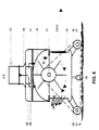
- the suction device 5 contains a central pressure chamber 16 (see FIGS. 3 and 5), in which on an axis of rotation 17 or rotatable about a fixed axis Water wheel 18 is arranged.
- the pressure line 15 merges into a nozzle 19, which ends in two separate passages 20, 21 in the pressure chamber 16, the are arranged symmetrically to the central axis ZA (Fig. 5) at a distance from this.
- the passages 20, 21 is preceded by a two-way valve 22, which is optional closes one of the two passages and opens the other or vice versa.
- the central pressure chamber 16 longitudinal slots 23 with flaps 24, the Flaps 24 are arranged so that they move with a flow close from above and open when there is a flow from below (see the arrows with black heads in Fig. 5).
- the axis 17 or that is Water wheel 18 with a vehicle in the form of belts preferably two spaced-apart toothed belt 25 coupled (in the 3 is shown only one).
- the timing belt 25 are with preferably at the end of arms 26 on the housing of the suction device 5 rotatably mounted deflection rollers or deflection gears 27 and can in the intermediate area at least via a support roller or a support gear 28 be guided.
- the toothed belt 25 preferably also have double-sided teeth. At a Such execution form inclinations of the floor and also slight Levels no problem.
- brushes 29 There are fixed and / or rotating between the vehicle and the side of it and / or up and down and / or forward and backward movements executing brushes 29 (see. Fig. 3) provided in contact with the bottom 6th the tub 2 stand.
- the brushes 29 can, in order to compensate for wear, be arranged adjustable and possibly also be driven what preferably via a coupling with the drive of the vehicle, if necessary with the involvement of a gear to change the Movement speed or the rotation speed or the Frequency of the intended rotational and / or forward and backward movements of the Brushes 29 may be arranged.
- Rotating brushes can also be used as Vehicle are used.
- suction spaces 30 In particular on both sides of the central pressure chamber 16 there are suction spaces 30 (in Fig. 1 is shown on one side only, a suction chamber) arranged over a arranged above the central chamber 16 channel 31 with the Connection piece 32 of the suction line 14 are connected.
- Towards the Bottom 6 of the tub 2 have the suction spaces 30 in the vicinity of the brushes 29 Intake openings 33 (see Fig. 4).
- each end with the Suction chambers 30 is connected.
- These channels 34 can be slit-shaped and / or have annular suction openings 33 '.
- the suction device 5 should preferably be one Cross section of the tub 2, preferably the one with the smallest dimensions, be carried out overlapping. If necessary, this can be done by side approaches or boom (not shown), which is then also fixed or movable Brushes should be achieved. To make a directional move too ensure and tilting of the suction device 5 during its To prevent longitudinal movements within the tub 2, the Suction device 5 can be designed with a guide system that also Arrangements in the side walls of the laundry chamber 1 includes.
- 3 is a possible guidance system of this type is indicated, which consists of two spaced apart Guide rollers 37 (only one of which is shown) on each face of the Suction device 5 and one each in the side walls of the tub 2, guide rail 38, preferably above the water level 12 there is, if necessary, brushing devices for cleaning the Guide rails 38 may be provided (not shown).
- Guide rollers 37 only one of which is shown
- guide rail 38 preferably above the water level 12 there is, if necessary, brushing devices for cleaning the Guide rails 38 may be provided (not shown).
- anyone can any other known guide can be used, e.g. B. also a remote-controlled system that the vacuum cleaner any free or allows predetermined movement across the floor, which is especially true for larger ones Tubs make sense where a cross-sectional vacuum cleaner only would be difficult or impossible to handle.
- Suction devices 5 arranged side by side and coupled together be used.
- Each of the suction devices 5 can be practically identical be constructed and coupled purely mechanically. But there is also the possibility, especially smaller modules, at both ends of one Arrange suction device 5, the drive of the water wheel 18 via a Coupling with the rotatable axis 17 are transmitted to the secondary modules can.
- a flexible connecting line can connect the suction chamber 30 connect to corresponding chambers of the secondary modules. This can also be done by a direct connection via a closable opening 39 (see FIG. 3) in the Suction chamber 30 can be done.
- the device for cleaning tubs works as follows: In the case of one arranged on the bottom of a tub in accordance with the above Description executed suction device 5 is cleaned liquid (Water) through the pressure line 15 into the suction device 5. Depending on Position of the two-way valve 22 is laterally the central axis ZA pressurized water fed to the wings of the water wheel 18. This turns the waterwheel 18 in Rotation offset and indicated by closed arrows in Fig. 5 Water flow achieved. This flow closes the downward movement Flaps 24 of the slots 23 so that there is a closed wall.
- the suction device 5 thus driven actuates one end of the tub 2 Limit switch, not shown, on the suction device 5 in contact with the Front wall of the two-way valve 22, whereby the passage 21 is closed and the passage 20 is opened, whereby the new supply of the Pressurized water flow according to the open arrow in Fig. 5 a reversal of the direction Movement of the water wheel 18 is caused, which also causes a Reversal of movement is achieved.
- the suction device 5 moves automatically over the entire tub floor, constantly moving it back and forth and holding suction and mechanical cleaning with the brushes free of deposits.
- the speed of the movement can be changed by changing the feed Water pressure may also be influenced by adjustable throttle valves become.
- the bottom 6 of the tub 2 is always mechanical processed so that no deposits build up on the bottom of the tub can.
- Sinking particles are whirled up from the floor so that they can be particularly easily detected by the suction flow.
- the suction areas at the ends of the device become the most vulnerable Edge areas vacuumed more intensely, so that at these critical edge areas Deposits can be prevented.
- the measures according to the invention allow one continuous cleaning of the tub from inorganic and / or organic Deposits and allow the service life of facilities that the Subject of the invention included to extend significantly.
Landscapes
- Engineering & Computer Science (AREA)
- Architecture (AREA)
- Civil Engineering (AREA)
- Structural Engineering (AREA)
- Cleaning By Liquid Or Steam (AREA)
- Cleaning In General (AREA)
- Separation Of Particles Using Liquids (AREA)
- Basic Packing Technique (AREA)
- Cleaning Or Drying Semiconductors (AREA)
- Manufacturing Of Printed Wiring (AREA)
- Vehicle Cleaning, Maintenance, Repair, Refitting, And Outriggers (AREA)
Priority Applications (1)
| Application Number | Priority Date | Filing Date | Title |
|---|---|---|---|
| SI9730401T SI0918913T1 (en) | 1996-08-16 | 1997-08-14 | Device for cleaning tubs which contain liquid in working conditions, and use of the device in a washer chamber |
Applications Claiming Priority (3)
| Application Number | Priority Date | Filing Date | Title |
|---|---|---|---|
| DE19633057A DE19633057C1 (de) | 1996-08-16 | 1996-08-16 | Vorrichtung zum Reinigen von Wannen, die bei Betriebsbedingungen Flüssigkeit enthalten |
| DE19633057 | 1996-08-16 | ||
| PCT/EP1997/004470 WO1998007936A1 (de) | 1996-08-16 | 1997-08-14 | Vorrichtung zum reinigen von wannen, die bei betriebsbedingungen flüssigkeit enthalten und verwendung der vorrichtung in einer wäscherkammer |
Publications (2)
| Publication Number | Publication Date |
|---|---|
| EP0918913A1 EP0918913A1 (de) | 1999-06-02 |
| EP0918913B1 true EP0918913B1 (de) | 2002-07-03 |
Family
ID=7802802
Family Applications (1)
| Application Number | Title | Priority Date | Filing Date |
|---|---|---|---|
| EP97943812A Expired - Lifetime EP0918913B1 (de) | 1996-08-16 | 1997-08-14 | Vorrichtung zum reinigen von wannen, die bei betriebsbedingungen flüssigkeit enthalten und verwendung der vorrichtung in einer wäscherkammer |
Country Status (19)
| Country | Link |
|---|---|
| US (1) | US6163914A (pl) |
| EP (1) | EP0918913B1 (pl) |
| JP (1) | JP2000516505A (pl) |
| KR (1) | KR20000068259A (pl) |
| CN (1) | CN1095916C (pl) |
| AT (1) | ATE220166T1 (pl) |
| AU (1) | AU720917B2 (pl) |
| CA (1) | CA2264114A1 (pl) |
| DE (2) | DE19633057C1 (pl) |
| DK (1) | DK0918913T3 (pl) |
| ES (1) | ES2179371T3 (pl) |
| NO (1) | NO312849B1 (pl) |
| NZ (1) | NZ334094A (pl) |
| PL (1) | PL184474B1 (pl) |
| PT (1) | PT918913E (pl) |
| RU (1) | RU2198042C2 (pl) |
| SK (1) | SK20799A3 (pl) |
| TR (1) | TR199900316T2 (pl) |
| WO (1) | WO1998007936A1 (pl) |
Families Citing this family (8)
| Publication number | Priority date | Publication date | Assignee | Title |
|---|---|---|---|---|
| DE19835239A1 (de) * | 1998-08-04 | 2000-02-24 | Johnson & Johnson Gmbh | Schäumende Ölzubereitung und deren Verwendung |
| US6532684B1 (en) * | 2000-10-12 | 2003-03-18 | General Electric Company | System for cleaning pressurized containers |
| US6926776B1 (en) | 2000-10-12 | 2005-08-09 | General Electric Company | Method for cleaning pressurized containers containing chlorine gas or sulfur dioxide gas |
| US6793740B1 (en) | 2000-10-12 | 2004-09-21 | General Electric Company | Method for cleaning pressurized containers containing moisture sensitive chemicals |
| US6758913B1 (en) | 2000-10-12 | 2004-07-06 | General Electric Company | Method of cleaning pressurized containers containing anhydrous ammonia |
| US8510889B2 (en) * | 2010-10-28 | 2013-08-20 | Wing-kin HUI | Automated pool cleaning vehicle with middle roller |
| CN110952808B (zh) * | 2019-12-19 | 2021-04-06 | 冯厉 | 一种具有自净功能的泳池及其使用方法 |
| CN113231391B (zh) * | 2021-05-28 | 2022-09-06 | 安徽普仁中药饮片有限公司 | 一种用于中药饮片加工的清洗装置 |
Family Cites Families (15)
| Publication number | Priority date | Publication date | Assignee | Title |
|---|---|---|---|---|
| US3254355A (en) * | 1965-01-22 | 1966-06-07 | James R Shaw | Swimming pool cleaning device |
| GB1459853A (en) * | 1974-02-19 | 1976-12-31 | Henkin M L | Automatic swimming pool cleaner |
| US4401576A (en) * | 1980-12-29 | 1983-08-30 | Meurer Industries, Inc. | Sediment collecting device |
| FR2535226A1 (fr) * | 1982-10-27 | 1984-05-04 | Sfermi | Dispositif a brosse pour le nettoyage et/ou la decontamination de surfaces |
| US4449265A (en) * | 1983-03-01 | 1984-05-22 | Hoy James S | Swimming pool sweep |
| DE3320923C2 (de) * | 1983-06-09 | 1987-04-16 | Peacock Investments (Proprietary) Ltd., Johannesburg, Transvaal | Saugreinigungsvorrichtung |
| FR2549745B1 (fr) * | 1983-07-27 | 1986-10-10 | Scp Biscornet | Procede de nettoyage par ultra-sons de surfaces et dispositif et installation mettant en oeuvre le procede |
| US4589986A (en) * | 1984-01-26 | 1986-05-20 | Alopex Industries, Inc. | Pool cleaner |
| US4558479A (en) * | 1984-01-26 | 1985-12-17 | Alopex Industries, Inc. | Pool cleaner |
| US5099535A (en) * | 1988-02-18 | 1992-03-31 | Daniel J. D. Chauvier | Cleaner for submerged surfaces |
| DE3808407A1 (de) * | 1988-03-14 | 1989-09-28 | Maisenhaelder Siegfried | Handbetaetigtes saugreinigungsgeraet fuer schwimmbecken |
| ES2021813B3 (es) * | 1988-08-20 | 1991-11-16 | Pooltec Estab | Cabezal de aspiracion para limpiar superficies sumergidas |
| FR2655575A3 (fr) * | 1989-12-12 | 1991-06-14 | Ravret Pierre | Appareil automatique de nettoyage de bassin. |
| US5337434A (en) * | 1993-04-12 | 1994-08-16 | Aqua Products, Inc. | Directional control means for robotic swimming pool cleaners |
| US5435031A (en) * | 1993-07-09 | 1995-07-25 | H-Tech, Inc. | Automatic pool cleaning apparatus |
-
1996
- 1996-08-16 DE DE19633057A patent/DE19633057C1/de not_active Expired - Fee Related
-
1997
- 1997-08-14 PL PL97331734A patent/PL184474B1/pl not_active IP Right Cessation
- 1997-08-14 TR TR1999/00316T patent/TR199900316T2/xx unknown
- 1997-08-14 KR KR1019997001394A patent/KR20000068259A/ko not_active Ceased
- 1997-08-14 ES ES97943812T patent/ES2179371T3/es not_active Expired - Lifetime
- 1997-08-14 DE DE59707659T patent/DE59707659D1/de not_active Expired - Fee Related
- 1997-08-14 SK SK207-99A patent/SK20799A3/sk unknown
- 1997-08-14 EP EP97943812A patent/EP0918913B1/de not_active Expired - Lifetime
- 1997-08-14 JP JP10510387A patent/JP2000516505A/ja active Pending
- 1997-08-14 CA CA002264114A patent/CA2264114A1/en not_active Abandoned
- 1997-08-14 AT AT97943812T patent/ATE220166T1/de not_active IP Right Cessation
- 1997-08-14 WO PCT/EP1997/004470 patent/WO1998007936A1/de not_active Ceased
- 1997-08-14 US US09/242,420 patent/US6163914A/en not_active Expired - Fee Related
- 1997-08-14 CN CN97198589A patent/CN1095916C/zh not_active Expired - Fee Related
- 1997-08-14 RU RU99105206/03A patent/RU2198042C2/ru not_active IP Right Cessation
- 1997-08-14 PT PT97943812T patent/PT918913E/pt unknown
- 1997-08-14 DK DK97943812T patent/DK0918913T3/da active
- 1997-08-14 NZ NZ334094A patent/NZ334094A/xx unknown
- 1997-08-14 AU AU45519/97A patent/AU720917B2/en not_active Ceased
-
1999
- 1999-02-10 NO NO19990624A patent/NO312849B1/no unknown
Also Published As
| Publication number | Publication date |
|---|---|
| CN1095916C (zh) | 2002-12-11 |
| DK0918913T3 (da) | 2002-11-11 |
| ES2179371T3 (es) | 2003-01-16 |
| PL331734A1 (en) | 1999-08-02 |
| DE19633057C1 (de) | 1998-03-12 |
| RU2198042C2 (ru) | 2003-02-10 |
| DE59707659D1 (de) | 2002-08-08 |
| SK20799A3 (en) | 2000-03-13 |
| CN1233309A (zh) | 1999-10-27 |
| TR199900316T2 (xx) | 1999-04-21 |
| ATE220166T1 (de) | 2002-07-15 |
| PL184474B1 (pl) | 2002-11-29 |
| AU720917B2 (en) | 2000-06-15 |
| KR20000068259A (ko) | 2000-11-25 |
| CA2264114A1 (en) | 1998-02-26 |
| NO990624L (no) | 1999-04-14 |
| NO990624D0 (no) | 1999-02-10 |
| WO1998007936A1 (de) | 1998-02-26 |
| EP0918913A1 (de) | 1999-06-02 |
| JP2000516505A (ja) | 2000-12-12 |
| US6163914A (en) | 2000-12-26 |
| NZ334094A (en) | 2000-09-29 |
| NO312849B1 (no) | 2002-07-08 |
| PT918913E (pt) | 2002-11-29 |
| AU4551997A (en) | 1998-03-06 |
Similar Documents
| Publication | Publication Date | Title |
|---|---|---|
| EP0989255B1 (de) | Schwimmbadreinrgungsgerät | |
| DE3540783A1 (de) | Fahrbare nassreinigungsmaschine | |
| EP0074966A1 (de) | Filtervorrichtung zur trennung von flüssigkeiten und feststoffen. | |
| DE102004001506A1 (de) | Tertiärfilter | |
| DE4106088A1 (de) | Saugdruckfass | |
| EP1108822B1 (de) | Abwasserhebeanlage | |
| DE19633057C1 (de) | Vorrichtung zum Reinigen von Wannen, die bei Betriebsbedingungen Flüssigkeit enthalten | |
| DE10240454B4 (de) | Teichfilter mit Vorfiltereinheit | |
| DE4017013C2 (de) | Vorrichtung zum Reinigen von Brunnenschächten | |
| DE2743530A1 (de) | Vorrichtung zum reinigen von grossflaechigen textilauflagen, insbesondere von teppichen und teppichboeden | |
| DE2710256A1 (de) | Abscheidevorrichtung mit sinkstoffabscheider, leichtstoffabscheider und entleerungseinrichtung | |
| EP0246562A2 (de) | Verfahren und Anlage zur Verbesserung des Durchflusses eines Abflussrohres | |
| DE2232622C3 (de) | Klosettspülvorrichtung mit Umlauf der Reinigungsflüssigkeit | |
| EP0563754A1 (de) | Reinigungsvorrichtung | |
| EP0280648B1 (de) | Reinigungsvorrichtung für Becken in Kläranlagen | |
| DE102017109696A1 (de) | Reinigungsvorrichtung für Malerwerkzeug | |
| EP0582034A2 (de) | Vorrichtung zur Zufuhr oder zum Absaugen eines Mediums | |
| DE3808407A1 (de) | Handbetaetigtes saugreinigungsgeraet fuer schwimmbecken | |
| EP1760046B1 (de) | Kompaktes Wasserreinigungsgerät für Teiche | |
| DE102004058150C5 (de) | Vorrichtung zum Waschen bzw. Reinigen von Behältern, insbesondere Flaschenkästen | |
| DE10115019B4 (de) | Regenwasserfilter mit einem Filtergehäuse und Verfahren zum Reinigen eines Regenwasserfilters | |
| CH681174A5 (en) | Cleaning device for heat exchangers in waste air/gas channels - consists of modular movable upright washing column with driven movable spray nozzles | |
| DE3300596C1 (de) | Siebanlage fuer die mechanische Reinigung von in einem offenen Gerinne fliessendem Wasser | |
| DE19537578A1 (de) | Einrichtung zur mechanischen Reinigung von verschmutztem Wasser oder Abwasser | |
| EP2226450A2 (de) | Schwallwasser-Überlauf-Sammelsystem für Schwimmbäder, Whirlpools, Bewegungsbäder, Therapiebäder und dergleichen |
Legal Events
| Date | Code | Title | Description |
|---|---|---|---|
| PUAI | Public reference made under article 153(3) epc to a published international application that has entered the european phase |
Free format text: ORIGINAL CODE: 0009012 |
|
| 17P | Request for examination filed |
Effective date: 19990312 |
|
| AK | Designated contracting states |
Kind code of ref document: A1 Designated state(s): AT BE CH DE DK ES FI FR GB GR IE IT LI LU MC NL PT SE |
|
| RAX | Requested extension states of the european patent have changed |
Free format text: LT PAYMENT 19990312;LV PAYMENT 19990312;SI PAYMENT 19990312 |
|
| GRAG | Despatch of communication of intention to grant |
Free format text: ORIGINAL CODE: EPIDOS AGRA |
|
| 17Q | First examination report despatched |
Effective date: 20010827 |
|
| GRAG | Despatch of communication of intention to grant |
Free format text: ORIGINAL CODE: EPIDOS AGRA |
|
| GRAH | Despatch of communication of intention to grant a patent |
Free format text: ORIGINAL CODE: EPIDOS IGRA |
|
| GRAH | Despatch of communication of intention to grant a patent |
Free format text: ORIGINAL CODE: EPIDOS IGRA |
|
| GRAA | (expected) grant |
Free format text: ORIGINAL CODE: 0009210 |
|
| AK | Designated contracting states |
Kind code of ref document: B1 Designated state(s): AT BE CH DE DK ES FI FR GB GR IE IT LI LU MC NL PT SE |
|
| AX | Request for extension of the european patent |
Free format text: LT PAYMENT 19990312;LV PAYMENT 19990312;SI PAYMENT 19990312 |
|
| REF | Corresponds to: |
Ref document number: 220166 Country of ref document: AT Date of ref document: 20020715 Kind code of ref document: T |
|
| REG | Reference to a national code |
Ref country code: CH Ref legal event code: EP |
|
| REG | Reference to a national code |
Ref country code: IE Ref legal event code: FG4D Free format text: GERMAN |
|
| PGFP | Annual fee paid to national office [announced via postgrant information from national office to epo] |
Ref country code: GB Payment date: 20020807 Year of fee payment: 6 |
|
| REF | Corresponds to: |
Ref document number: 59707659 Country of ref document: DE Date of ref document: 20020808 |
|
| PGFP | Annual fee paid to national office [announced via postgrant information from national office to epo] |
Ref country code: FR Payment date: 20020819 Year of fee payment: 6 Ref country code: NL Payment date: 20020819 Year of fee payment: 6 |
|
| PGFP | Annual fee paid to national office [announced via postgrant information from national office to epo] |
Ref country code: MC Payment date: 20020822 Year of fee payment: 6 Ref country code: DK Payment date: 20020822 Year of fee payment: 6 Ref country code: BE Payment date: 20020822 Year of fee payment: 6 Ref country code: AT Payment date: 20020822 Year of fee payment: 6 |
|
| PGFP | Annual fee paid to national office [announced via postgrant information from national office to epo] |
Ref country code: LU Payment date: 20020823 Year of fee payment: 6 Ref country code: SE Payment date: 20020823 Year of fee payment: 6 Ref country code: FI Payment date: 20020823 Year of fee payment: 6 Ref country code: CH Payment date: 20020823 Year of fee payment: 6 |
|
| PGFP | Annual fee paid to national office [announced via postgrant information from national office to epo] |
Ref country code: IE Payment date: 20020826 Year of fee payment: 6 Ref country code: ES Payment date: 20020826 Year of fee payment: 6 |
|
| PGFP | Annual fee paid to national office [announced via postgrant information from national office to epo] |
Ref country code: PT Payment date: 20021001 Year of fee payment: 6 |
|
| PGFP | Annual fee paid to national office [announced via postgrant information from national office to epo] |
Ref country code: GR Payment date: 20021007 Year of fee payment: 6 |
|
| PGFP | Annual fee paid to national office [announced via postgrant information from national office to epo] |
Ref country code: DE Payment date: 20021022 Year of fee payment: 6 |
|
| GBT | Gb: translation of ep patent filed (gb section 77(6)(a)/1977) |
Effective date: 20021003 |
|
| REG | Reference to a national code |
Ref country code: DK Ref legal event code: T3 |
|
| REG | Reference to a national code |
Ref country code: PT Ref legal event code: SC4A Free format text: AVAILABILITY OF NATIONAL TRANSLATION Effective date: 20020927 |
|
| REG | Reference to a national code |
Ref country code: GR Ref legal event code: EP Ref document number: 20020403276 Country of ref document: GR |
|
| ET | Fr: translation filed | ||
| REG | Reference to a national code |
Ref country code: CH Ref legal event code: NV Representative=s name: BRAUN & PARTNER PATENT-, MARKEN-, RECHTSANWAELTE |
|
| REG | Reference to a national code |
Ref country code: ES Ref legal event code: FG2A Ref document number: 2179371 Country of ref document: ES Kind code of ref document: T3 |
|
| PLBE | No opposition filed within time limit |
Free format text: ORIGINAL CODE: 0009261 |
|
| STAA | Information on the status of an ep patent application or granted ep patent |
Free format text: STATUS: NO OPPOSITION FILED WITHIN TIME LIMIT |
|
| 26N | No opposition filed |
Effective date: 20030404 |
|
| PG25 | Lapsed in a contracting state [announced via postgrant information from national office to epo] |
Ref country code: LU Free format text: LAPSE BECAUSE OF NON-PAYMENT OF DUE FEES Effective date: 20030814 Ref country code: IE Free format text: LAPSE BECAUSE OF NON-PAYMENT OF DUE FEES Effective date: 20030814 Ref country code: GB Free format text: LAPSE BECAUSE OF NON-PAYMENT OF DUE FEES Effective date: 20030814 Ref country code: FI Free format text: LAPSE BECAUSE OF NON-PAYMENT OF DUE FEES Effective date: 20030814 Ref country code: AT Free format text: LAPSE BECAUSE OF NON-PAYMENT OF DUE FEES Effective date: 20030814 |
|
| PG25 | Lapsed in a contracting state [announced via postgrant information from national office to epo] |
Ref country code: SE Free format text: LAPSE BECAUSE OF NON-PAYMENT OF DUE FEES Effective date: 20030815 |
|
| PG25 | Lapsed in a contracting state [announced via postgrant information from national office to epo] |
Ref country code: ES Free format text: LAPSE BECAUSE OF NON-PAYMENT OF DUE FEES Effective date: 20030816 |
|
| PG25 | Lapsed in a contracting state [announced via postgrant information from national office to epo] |
Ref country code: MC Free format text: LAPSE BECAUSE OF NON-PAYMENT OF DUE FEES Effective date: 20030831 Ref country code: LI Free format text: LAPSE BECAUSE OF NON-PAYMENT OF DUE FEES Effective date: 20030831 Ref country code: CH Free format text: LAPSE BECAUSE OF NON-PAYMENT OF DUE FEES Effective date: 20030831 Ref country code: BE Free format text: LAPSE BECAUSE OF NON-PAYMENT OF DUE FEES Effective date: 20030831 |
|
| PG25 | Lapsed in a contracting state [announced via postgrant information from national office to epo] |
Ref country code: DK Free format text: LAPSE BECAUSE OF NON-PAYMENT OF DUE FEES Effective date: 20030901 |
|
| BERE | Be: lapsed |
Owner name: *SOLKE GEB. ORTMANN SIEGLINDE Effective date: 20030831 Owner name: *MARTIN KURT Effective date: 20030831 |
|
| PG25 | Lapsed in a contracting state [announced via postgrant information from national office to epo] |
Ref country code: PT Free format text: LAPSE BECAUSE OF NON-PAYMENT OF DUE FEES Effective date: 20040229 |
|
| PG25 | Lapsed in a contracting state [announced via postgrant information from national office to epo] |
Ref country code: NL Free format text: LAPSE BECAUSE OF NON-PAYMENT OF DUE FEES Effective date: 20040301 |
|
| PG25 | Lapsed in a contracting state [announced via postgrant information from national office to epo] |
Ref country code: DE Free format text: LAPSE BECAUSE OF NON-PAYMENT OF DUE FEES Effective date: 20040302 |
|
| PG25 | Lapsed in a contracting state [announced via postgrant information from national office to epo] |
Ref country code: GR Free format text: LAPSE BECAUSE OF NON-PAYMENT OF DUE FEES Effective date: 20040303 |
|
| EUG | Se: european patent has lapsed | ||
| REG | Reference to a national code |
Ref country code: DK Ref legal event code: EBP |
|
| GBPC | Gb: european patent ceased through non-payment of renewal fee |
Effective date: 20030814 |
|
| REG | Reference to a national code |
Ref country code: CH Ref legal event code: PL |
|
| LTLA | Lt: lapse of european patent or patent extension |
Effective date: 20030814 |
|
| PG25 | Lapsed in a contracting state [announced via postgrant information from national office to epo] |
Ref country code: FR Free format text: LAPSE BECAUSE OF NON-PAYMENT OF DUE FEES Effective date: 20040430 |
|
| NLV4 | Nl: lapsed or anulled due to non-payment of the annual fee |
Effective date: 20040301 |
|
| REG | Reference to a national code |
Ref country code: PT Ref legal event code: MM4A Free format text: LAPSE DUE TO NON-PAYMENT OF FEES Effective date: 20040229 |
|
| REG | Reference to a national code |
Ref country code: IE Ref legal event code: MM4A |
|
| REG | Reference to a national code |
Ref country code: FR Ref legal event code: ST |
|
| REG | Reference to a national code |
Ref country code: ES Ref legal event code: FD2A Effective date: 20030816 |
|
| PG25 | Lapsed in a contracting state [announced via postgrant information from national office to epo] |
Ref country code: IT Free format text: LAPSE BECAUSE OF NON-PAYMENT OF DUE FEES;WARNING: LAPSES OF ITALIAN PATENTS WITH EFFECTIVE DATE BEFORE 2007 MAY HAVE OCCURRED AT ANY TIME BEFORE 2007. THE CORRECT EFFECTIVE DATE MAY BE DIFFERENT FROM THE ONE RECORDED. Effective date: 20050814 |