EP0918589B1 - Maschine zum bearbeiten von werkstücken mit schneidzähnen, insbesondere von sägeblättern - Google Patents
Maschine zum bearbeiten von werkstücken mit schneidzähnen, insbesondere von sägeblättern Download PDFInfo
- Publication number
- EP0918589B1 EP0918589B1 EP97934503A EP97934503A EP0918589B1 EP 0918589 B1 EP0918589 B1 EP 0918589B1 EP 97934503 A EP97934503 A EP 97934503A EP 97934503 A EP97934503 A EP 97934503A EP 0918589 B1 EP0918589 B1 EP 0918589B1
- Authority
- EP
- European Patent Office
- Prior art keywords
- workpiece
- machine
- tool
- axis
- slide
- Prior art date
- Legal status (The legal status is an assumption and is not a legal conclusion. Google has not performed a legal analysis and makes no representation as to the accuracy of the status listed.)
- Expired - Lifetime
Links
Images






Classifications
-
- B—PERFORMING OPERATIONS; TRANSPORTING
- B23—MACHINE TOOLS; METAL-WORKING NOT OTHERWISE PROVIDED FOR
- B23D—PLANING; SLOTTING; SHEARING; BROACHING; SAWING; FILING; SCRAPING; LIKE OPERATIONS FOR WORKING METAL BY REMOVING MATERIAL, NOT OTHERWISE PROVIDED FOR
- B23D63/00—Dressing the tools of sawing machines or sawing devices for use in cutting any kind of material, e.g. in the manufacture of sawing tools
- B23D63/005—Workpiece indexing equipment specially adapted to form part of sawing tool dressing machines
- B23D63/0055—Workpiece indexing equipment specially adapted to form part of sawing tool dressing machines with tooth engaging feed
-
- B—PERFORMING OPERATIONS; TRANSPORTING
- B23—MACHINE TOOLS; METAL-WORKING NOT OTHERWISE PROVIDED FOR
- B23D—PLANING; SLOTTING; SHEARING; BROACHING; SAWING; FILING; SCRAPING; LIKE OPERATIONS FOR WORKING METAL BY REMOVING MATERIAL, NOT OTHERWISE PROVIDED FOR
- B23D63/00—Dressing the tools of sawing machines or sawing devices for use in cutting any kind of material, e.g. in the manufacture of sawing tools
- B23D63/08—Sharpening the cutting edges of saw teeth
- B23D63/12—Sharpening the cutting edges of saw teeth by grinding
-
- B—PERFORMING OPERATIONS; TRANSPORTING
- B24—GRINDING; POLISHING
- B24B—MACHINES, DEVICES, OR PROCESSES FOR GRINDING OR POLISHING; DRESSING OR CONDITIONING OF ABRADING SURFACES; FEEDING OF GRINDING, POLISHING, OR LAPPING AGENTS
- B24B3/00—Sharpening cutting edges, e.g. of tools; Accessories therefor, e.g. for holding the tools
-
- B—PERFORMING OPERATIONS; TRANSPORTING
- B24—GRINDING; POLISHING
- B24B—MACHINES, DEVICES, OR PROCESSES FOR GRINDING OR POLISHING; DRESSING OR CONDITIONING OF ABRADING SURFACES; FEEDING OF GRINDING, POLISHING, OR LAPPING AGENTS
- B24B47/00—Drives or gearings; Equipment therefor
- B24B47/22—Equipment for exact control of the position of the grinding tool or work at the start of the grinding operation
-
- B—PERFORMING OPERATIONS; TRANSPORTING
- B24—GRINDING; POLISHING
- B24B—MACHINES, DEVICES, OR PROCESSES FOR GRINDING OR POLISHING; DRESSING OR CONDITIONING OF ABRADING SURFACES; FEEDING OF GRINDING, POLISHING, OR LAPPING AGENTS
- B24B49/00—Measuring or gauging equipment for controlling the feed movement of the grinding tool or work; Arrangements of indicating or measuring equipment, e.g. for indicating the start of the grinding operation
- B24B49/02—Measuring or gauging equipment for controlling the feed movement of the grinding tool or work; Arrangements of indicating or measuring equipment, e.g. for indicating the start of the grinding operation according to the instantaneous size and required size of the workpiece acted upon, the measuring or gauging being continuous or intermittent
Definitions
- the invention relates to a machine for machining workpieces with cutting teeth, especially of saw blades the preamble of claim 1.
- the machining, rotationally symmetrical and rotatable tool be it one or more Grinding wheels or EDM wheels may be formed even while machining a workpiece or even one single tooth wears so much that dimensional changes of the tool taken into account in the further processing of the workpiece Need to become.
- time-consuming measurements have to be carried out be carried out on the tool.
- an initial dimension is usually determined before processing, to correctly position the workpiece for machining can. For example, the diameter of circular saws must be specified during processing.
- the intended Processing position is for a machine of the type mentioned generally the one in which the tip of the to be machined Cutting tooth on the one defined as the swivel axis Axis lies. Under tooth tip is in general, and so too here to understand a sharp edge from a tooth face and a tooth back, also called free space, is formed.
- the invention has for its object an automatic To enable the aforementioned measurement and correction processes to be carried out.
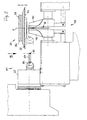
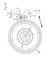
- Workpiece 10 is a circular saw with carbide-tipped Cutting teeth 12 shown, each of which on its tooth face 14 and to be grinded on his tooth back 16 while its tooth tip 18 exactly maintains a predetermined position.
- the machine shown has a machine frame 20 on which an elongated pivot body 22 around one shown in Example of a horizontal swivel axis A with swivel adjustment is.
- the pivot axis A is defined as a section line vertical first reference plane B and a horizontal second Reference plane C.
- A extends along the swivel body 22
- Lift axis D which is the pivot axis A at a right angle intersects and represents the axis of movement of a lifting carriage 24.
- the lifting carriage is on the swivel body 22 along the lifting axis D guided back and forth and about the lifting axis D adjustable.
- a tool slide 26 is deliverable on the lifting slide 24 guided.
- the spindle axis E is the axis of an am Tool slide 26 mounted, rotatably driven tool spindle 28 on which there is a tool 30 for machining the workpiece 10 can be attached.
- the tool 30 is a combination of grinding wheels, which is composed of a plate-shaped first grinding wheel 32 with a flat annular first End face 34 and a cup-shaped second grinding wheel 36 with a likewise flat, annular second end face 38.
- the two grinding wheels 32 and 36 are coaxial with one another, Back to back, tightened so that the second End face 38 faces away from the first end face 34.
- the first grinding wheel 32 has a larger diameter than that second grinding wheel 36 and is intended to be used with the first Face 34 of the tooth face 14 of a cutting tooth 12 to grind.
- the second grinding wheel with a smaller diameter 36 is intended with the second end face 38 the tooth back 16 to grind.
- the grinding wheel combination can also use a single grinding wheel as tool 30 or EDM disc or a combination of two EDM discs be provided.
- the tool slide 26 corresponding to the slope the tooth face 14 to be machined is pivoted about the lifting axis D.
- Example arranged horizontal guide 40 which itself extends at a right angle to the pivot axis A.
- a workpiece carriage 42 is slidable carries a workpiece holder 44.
- a mandrel which has an axis of rotation F parallel to the pivot axis A. defined for the workpiece 10; the workpiece is placed on this mandrel 10 plugged in centrally.
- the workpiece carriage 42 is set so that the circle around the axis of rotation F, on which all the tooth tips 18 of the workpiece 10 lie Swiveling axis A intersects.
- the workpiece 10 can thus be gradually turn into machining positions, in each a tooth tip 18 lies on the pivot axis A.
- the axis of rotation F normal, vertical in the example shown Center plane G of the workpiece 10 is arranged so that it Lift axis D contains. In this position, the workpiece 10 clamped between two clamping jaws 46 of a clamping device.
- the tooth tip 18 of the cutting tooth 12 to be machined is there arranged at a point H, in which the pivot axis A is the central plane G pierces.
- a feed device 50 with a Rod 52 which is CNC-controlled along a feed axis I is extendable and carries a feed head 54 at its end.
- a cross slide is parallel to the swivel axis A on the feed head 54 56 slidably guided, the one feed finger 58th wearing.
- the cross slide 56 normally takes a rest position one in which the feed finger 58 is off the central plane G is arranged; only if a feed movement is to be carried out is, the cross slide 56 is parallel to the pivot axis A moved to a position in which the feed finger 58 in the tooth gap before the next cutting tooth 12 to be machined immersed and then by extending the rod 52 against the Breast of tooth 14 of this tooth presses and into the described Position in which the tooth tip 18 with the point H matches. It can be seen that the feed axis I only adapted approximately to the path of movement of the tooth face 14 can be advanced by the feed finger 58.
- the machine shown is from known type, for example according to the aforementioned Prospectus of the applicant. This includes that the machine is a known numerical control, not shown, with of all the movements mentioned can be controlled according to a program are.
- the tool 30 and the Feed device 50 can be on the machine shown determine with a measuring device 60 to the control mentioned connected.
- a measuring slide belongs to the measuring device 60 62, along the pivot axis A from that in FIG. 3 Rest position drawn with full lines to that with dashed lines Lines indicated measurement position is displaceable.
- a measuring probe 64 is a measuring probe 64 by means of a joint 66 stored in the manner of a ball joint in such a way that it around this Articulated joint can be deflected to all sides, whereby he signals according to the direction of its deflection to the Control device delivers.
- a simple fastener 68 shown as an example is a hexagon socket screw, a probe body 70 easily exchangeable, however, in a precisely reproducible location assignment to Probe 64, attached.
- the probe body 70 is made of a particularly hard material such as hard metal or polycrystalline diamond, so that it has little is prone to wear. It can be used for a dressing tool commercially available EDM discs are replaced if such as Tool 30 can be used.
- the measuring device 60 to use:
- the feed device 50 operated once, her feed finger 58 the from the tooth tip 18 outgoing tooth face 14 into a Position in which this tooth tip is reasonably accurate the horizontal second reference plane C.
- This process provisional positioning can be omitted if on others Appropriate prepositioning has been ensured is, for example by manual application of the tooth face mentioned 14 to a stop or by using a robot, which pre-positions the workpiece 10 of the machine shown feeds.
- the measuring slide 62 is extended so that the Probe body 70 assumes its measuring position in the central plane G, and then the workpiece carriage 42 continues to creep moved forward until said tooth tip 14 against the vertical first touch surface 72 of the probe body 70 abuts.
- the measuring device 60 emits a signal, due to which the control device the diameter of the im shown example as a workpiece 10 saw blade can calculate since you the position of the workpiece carriage 42, and thus also the axis of rotation F is known. Knowing the Diameter in many cases, with suitable typing, clear conclusions about further data of the workpiece 10, for example, its tooth pitch.
- the measuring slide 62 now returns to its rest position.
- the workpiece carriage 42 In order to finally position the workpiece 10, the workpiece carriage 42 finally moved back a distance that with the known distance of the first tactile surface 72 of the deflected probe body 70 from the vertical first reference plane B matches.
- the tooth face 14 of the first to be machined Cutting tooth 12 is then at point H on the pivot axis A.
- the clamping device 48 In this position the clamping device 48 is closed, so that the workpiece 10 is no longer unintentionally can move.
- the positioned cutting tooth 12 ground by the tool 30, for example initially from the first end face 34 to the tooth face 14 and later from the second end face 38 on the tooth back 16.
- the tool 30 is also subject to wear-related changes in predetermined intervals measured and compensated.
- the first end face 34 does this by the lifting slide 24 is program-controlled in a swivel position is brought in which this end face 34 horizontally, that is parallel arranged to the second touch surface 74 of the probe body 70 is.
- the tool slide 26 is then advanced as far as until the first end face 34 of the tool 30 is the second touch surface 74 touches the probe body 70 and thereby a signal of Measuring device 60 triggers the necessary correction of the Position caused by the tool slide 26 during grinding the next tooth breast 14 occupies.
- the effective diameter of the disc-shaped grinding wheel 32 decreases due to wear, it can also in predetermined Intervals are automatically measured by the Swivel body 22 is brought into a position in which the first end face 34 of the tool 30 normal to the third Touch surface 76 of the probe body extends. Then the tool spindle 28 by means of the tool slide 26 in the usual way Way assigned cross slide in the sense of the double arrow in Fig. 8 across the spindle axis E until the outer edge of the first grinding wheel 32 against the third touch surface 76 of the probe body 70 bumps, which in turn causes a correction signal is triggered.
- the tool 30 has in addition to its unchanged cup-shaped second grinding wheel 36 a smaller and thin first grinding wheel 32 intended for each cutting tooth 12, starting from its tooth back 16, one in the central plane G to incorporate horizontal chip breaker groove.
- the diameter this modified first grinding wheel 32 takes due to wear relatively quickly and must therefore in accordingly short predetermined intervals can be measured. This happens according to Fig. 11, and this is followed by a corresponding Compensation on.
Landscapes
- Engineering & Computer Science (AREA)
- Mechanical Engineering (AREA)
- Finish Polishing, Edge Sharpening, And Grinding By Specific Grinding Devices (AREA)
- Machine Tool Sensing Apparatuses (AREA)
- Automatic Control Of Machine Tools (AREA)
Description
- Fig. 1
- die erfindungsgemäße Maschine von vorne,
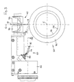
- Fig. 2
- eine vergrößerte Teilansicht in Richtung des Pfeils II in Fig. 1,
- Fig. 3
- die zugehörige Draufsicht qemäß Pfeil III in Fig. 2.
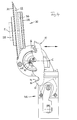
- Fig. 4
- einen vergrößerten Ausschnitt aus Fig. 1 in einer ersten Phase eines Betriebszyklus der Maschine,
- Fig. 5 bis 10
- entsprechende Ausschnitte in weiteren Phasen eines Betriebszyklus,
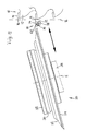
- Fig. 11
- einen vergrößerten Ausschnitt aus Fig. 3, jedoch bei einer abgewandelten Werkzeugausstattung der Maschine, und
- Fig. 12
- einen Ausschnitt ähnlich Fig.7, jedoch bei einer weiter abgewandelten Werkzeugausstattung der Maschine.
Claims (6)
- Maschine zum Bearbeiten von Werkstücken (10) mit Schneidzähnen (12), insbesondere von Sägeblättern, miteinem Maschinengestell (20) an dem eine Schwenkachse (A) festgelegt ist, in der sich eine erste und eine zweite Bezugsebene (B,C) schneiden,einem Schwenkkörper (22), der um die Schwenkachse (A) schwenkbar ist und eine zu dieser querverlaufende Hubachse (D) definiert,einem Hubschlitten (24), der am Schwenkkörper (22) längs der Hubachse (D) verschiebbar geführt ist,einem Werkzeugschlitten (26), der eine zur Hubachse (D) querverlaufende Spindelachse (E) definiert und längs dieser zustellbar am Hubschlitten (24) geführt ist,einer Werkzeugspindel (28), die am Werkzeugschlitten (26) um die Spindelachse (E) drehantreibbar gelagert und mit einem rotationssymmetrischen Werkzeug (30) bestückbar ist,einem Werkstückschlitten (42), der am Maschinengestell (20) quer zur ersten Bezugsebene (B) verschiebbar geführt ist und mit einer an ihm ausgebildeten Werkstückhalterung (44) eine zur Schwenkachse (A) normale Mittelebene (G) definiert,einer Vorschubeinrichtung (50) mit einem Vorschubfinger (58), der intermittierend an jeweils einen Schneidzahn (12) eines in der Werkstückhalterung (44) aufgenommenen Werkstücks (10) anlegbar ist, um dieses vorzuschieben, undeiner Steuerung für Bewegungen des Werkzeugschlittens (26), des Werkstückschlittens (42) und des Vorschubfingers (58), dadurch gekennzeichnet, daßzum Ermitteln des Abstandes der Schneidzähne (12) des Werkstücks (10) von der Werkstückhalterung (44) sowie zum Ermitteln mindestens einer den Abnutzungszustand des Werkzeugs (30) oder des Vorschubfingers (58) wiedergebenden Meßgröße ein gemeinsamer Tastkörper (70) vorgesehen ist, der aus einer zurückgezogenen Ruhestellung in eine Meßstellung in der Nähe des Punktes (H) bewegbar ist, in dem die Schwenkachse (A) die Mittelebene (G) durchdringt, unddie Steuerung dazu eingerichtet ist, die ermittelten Meßgrößen in Signale zum Steuern des Werkstückschlittens (42) sowie des Werkzeugschlittens (26) und/oder der Vorschubeinrichtung (50) umzusetzen.
- Maschine nach Anspruch 1,
dadurch gekennzeichnet, daß der Tastkörper (70) eine erste und eine zweite Tastfläche (72,74) aufweist, die zur ersten bzw. zweiten Bezugsebene (B bzw. C) parallel sind, und von denen die erste Tastfläche (72) zum Messen des Abstandes der Schneidzähne (12) von der Werkstückhalterung (44) vorgesehen ist, während die zweite Tastfläche (74) zum Messen eines Dickenmaßes des Vorschubfingers (58) und/oder des Werkzeugs (30) vorgesehen ist. - Maschine nach Anspruch 2,
dadurch gekennzeichnet, daß die erste und zweite Tastfläche (72,74) einen rechten Winkel miteinander einschließen. - Maschine nach Anspruch 2 oder 3,
dadurch gekennzeichnet, daß der Tastkörper (70) eine dritte Tastfläche (76) aufweist, die mit der zweiten Tastfläche (74) einen spitzen Winkel einschließt und zum Messen eines weiteren Dickenmaßes und/oder mindestens eines Radius des Werkzeugs (30) vorgesehen ist. - Maschine nach Anspruch 4,
dadurch gekennzeichnet, daß der Tastkörper (70) eine vierte Tastfläche (78) aufweist, die rechtwinklig zur ersten bis dritten Tastfläche (72,74,76) angeordnet ist. - Maschine nach einem der Ansprüche 1 bis 5,
dadurch gekennzeichnet, daß der Tastkörper (70) auch zum Abrichten des Werkzeugs (30) ausgebildet ist.
Applications Claiming Priority (3)
| Application Number | Priority Date | Filing Date | Title |
|---|---|---|---|
| DE19630057A DE19630057C1 (de) | 1996-07-25 | 1996-07-25 | Maschine zum Bearbeiten von Werkstücken mit Schneidzähnen |
| DE19630057 | 1996-07-25 | ||
| PCT/EP1997/003904 WO1998004379A1 (de) | 1996-07-25 | 1997-07-21 | Maschine zum bearbeiten von werkstücken mit schneidzähnen, insbesondere von sägeblättern |
Publications (2)
| Publication Number | Publication Date |
|---|---|
| EP0918589A1 EP0918589A1 (de) | 1999-06-02 |
| EP0918589B1 true EP0918589B1 (de) | 2000-05-03 |
Family
ID=7800827
Family Applications (1)
| Application Number | Title | Priority Date | Filing Date |
|---|---|---|---|
| EP97934503A Expired - Lifetime EP0918589B1 (de) | 1996-07-25 | 1997-07-21 | Maschine zum bearbeiten von werkstücken mit schneidzähnen, insbesondere von sägeblättern |
Country Status (5)
| Country | Link |
|---|---|
| US (1) | US6109137A (de) |
| EP (1) | EP0918589B1 (de) |
| JP (1) | JP4018150B2 (de) |
| DE (2) | DE19630057C1 (de) |
| WO (1) | WO1998004379A1 (de) |
Families Citing this family (15)
| Publication number | Priority date | Publication date | Assignee | Title |
|---|---|---|---|---|
| DE19743528C1 (de) * | 1997-10-01 | 1999-07-29 | Vollmer Werke Maschf | Meßeinrichtung an einer Maschine zum Bearbeiten von Werkstücken mit Schneidzähnen, insbes. von Sägeblättern |
| DE19743529C1 (de) * | 1997-10-01 | 1999-04-15 | Vollmer Werke Maschf | Maschine zum Bearbeiten von Werkstücken mit Schneidzähnen, insbesondere von Sägeblättern |
| DE19804762B4 (de) * | 1998-01-21 | 2005-07-21 | Vollmer Dornhan Gmbh & Co. Kg | Verfahren und Vorrichtung zum Schleifen der Frei-, Span- und/oder Brustfläche von Zähnen eines Sägewerkzeugs |
| DE19855773A1 (de) * | 1998-12-03 | 2000-06-15 | Walter Ag | Sägeblattschärfmaschine mit unabhängigen Zahnflankenschleifköpfen |
| DE19920099B4 (de) * | 1999-05-03 | 2006-12-14 | Walter Maschinenbau Gmbh | Positioniervorrichtung für Sägeblätter |
| US6631658B2 (en) | 2000-12-22 | 2003-10-14 | Pacific/Hoe Saw & Knife Company | Saw sharpening machine with pitch pre-measurement and feedback control for saw blade indexing |
| DE10121869A1 (de) * | 2001-05-05 | 2002-11-21 | Winter & Sohn Ernst | Verfahren zum Bearbeiten von mehrschneidigen Werkzeugen, bei denen die Schneiden auf einem Flugkreis liegen |
| DE10124203A1 (de) * | 2001-05-17 | 2002-12-05 | Vollmer Werke Maschf | Schleifmaschine zum beidseitigen Schleifen von Sägezahnflanken |
| CA2458340A1 (en) * | 2004-02-23 | 2005-08-23 | Michel Letendre | Indexing device for performing operational tasks on a tool element |
| WO2013091110A1 (en) | 2011-12-23 | 2013-06-27 | Williams And White Machine Inc. | Computer controlled multiple axis grinding machine for grinding saw blades |
| CZ2013911A3 (cs) * | 2013-11-20 | 2015-01-21 | Neva-Trade S.R.O. | Zařízení pro ostření pilových listů, pásů nebo kotoučů |
| CN105415105B (zh) * | 2015-10-29 | 2017-10-27 | 兰如林 | 刃磨机 |
| CN107309718B (zh) * | 2015-10-29 | 2019-05-10 | 兰如林 | 刃磨机 |
| US10625394B1 (en) * | 2018-02-06 | 2020-04-21 | Smith Sawmill Service LLC | Blade stop devices and methods |
| US12427593B2 (en) * | 2021-05-27 | 2025-09-30 | Ford Gin Services LLC | Gin blade sharpening system and method of use |
Family Cites Families (8)
| Publication number | Priority date | Publication date | Assignee | Title |
|---|---|---|---|---|
| US4357841A (en) * | 1980-05-19 | 1982-11-09 | Mote Terry A | Automatic grinding attachment for saw grinders |
| DE3120465C2 (de) * | 1981-05-22 | 1983-02-17 | Vollmer Werke Maschinenfabrik Gmbh, 7950 Biberach | Sägenschärfmaschine |
| DE3230278A1 (de) * | 1982-08-14 | 1984-02-16 | Vollmer Werke Maschinenfabrik Gmbh, 7950 Biberach | Klemmvorrichtung fuer ein saegeblatt an einer saegenbearbeitungsmaschine |
| DE3230277C2 (de) * | 1982-08-14 | 1986-02-06 | Vollmer Werke Maschinenfabrik Gmbh, 7950 Biberach | Vorrichtung zum Vorschieben eines Sägeblattes an einer Sägenbearbeitungsmaschine |
| DE3314601A1 (de) * | 1983-04-22 | 1984-10-25 | Vollmer Werke Maschinenfabrik Gmbh, 7950 Biberach | Steuerung einer saegenbearbeitungsmaschine |
| DE4110209C2 (de) * | 1991-03-28 | 1993-11-18 | Roland Man Druckmasch | Vorrichtung zur Justierung einer CNC-gesteuerten Schleifmaschine |
| DE4316789A1 (de) * | 1993-05-19 | 1994-11-24 | August Heinr Schmidt Gmbh & Co | Verfahren und Vorrichtung zum Schärfen eines Kreissägeblattes |
| DE19518710C1 (de) * | 1995-05-22 | 1996-11-28 | Vollmer Werke Maschf | Vorrichtung zum bahngesteuerten Schärfen von Sägeverzahnungen |
-
1996
- 1996-07-25 DE DE19630057A patent/DE19630057C1/de not_active Expired - Fee Related
-
1997
- 1997-07-21 EP EP97934503A patent/EP0918589B1/de not_active Expired - Lifetime
- 1997-07-21 WO PCT/EP1997/003904 patent/WO1998004379A1/de not_active Ceased
- 1997-07-21 DE DE59701601T patent/DE59701601D1/de not_active Expired - Lifetime
- 1997-07-21 JP JP50845998A patent/JP4018150B2/ja not_active Expired - Lifetime
- 1997-07-21 US US09/180,336 patent/US6109137A/en not_active Expired - Lifetime
Also Published As
| Publication number | Publication date |
|---|---|
| WO1998004379A1 (de) | 1998-02-05 |
| JP4018150B2 (ja) | 2007-12-05 |
| US6109137A (en) | 2000-08-29 |
| DE59701601D1 (de) | 2000-06-08 |
| DE19630057C1 (de) | 1997-09-18 |
| EP0918589A1 (de) | 1999-06-02 |
| JP2000515817A (ja) | 2000-11-28 |
Similar Documents
| Publication | Publication Date | Title |
|---|---|---|
| DE1502416C2 (de) | Schleifvorrichtung für die Schleifscheibe einer Walzenschleifmaschine. Ausscheidung aus: 1427485 | |
| DE10308292B4 (de) | Verfahren zum Rundschleifen bei der Herstellung von Werkzeugen aus Hartmetall und Rundschleifmaschine zum Schleifen von zylindrischen Ausgangskörpern bei der Herstellung von Werkzeugen aus Hartmetall | |
| EP2394783B1 (de) | Spitzenlose Rundschleifmaschine und Verfahren zum spitzenlosen Schleifen mit höhenverstellbarer Regelscheibe | |
| DE19630057C1 (de) | Maschine zum Bearbeiten von Werkstücken mit Schneidzähnen | |
| EP1719585A2 (de) | Maschinen zur Bearbeitung von optischen Werkstücken, insbesondere von Kunststoff-Brillengläsern | |
| EP2823924A2 (de) | Doppelabrichter | |
| DE2538737A1 (de) | Werkzeug-schleifmaschine | |
| EP0123956A2 (de) | Rundschleifmaschine zum Aussen- und Innenschleifen mit NC-Steuerung | |
| DE1577451C3 (de) | Verfahren zum Nachschleifen eines Werkzeugstahles | |
| EP0727280B1 (de) | Vorrichtung zum Polieren sphärischer Linsenoberfläche | |
| EP1019215B1 (de) | Maschine zum bearbeiten von werkstücken mit schneidzähnen, insbesondere von sägeblättern | |
| DE8425377U1 (de) | Schleifmaschine zum meßgesteuerten Gewindeschleifen | |
| EP1035938B1 (de) | Maschine zum bearbeiten von werkstücken mit schneidzähnen, insbes. von sägeblättern | |
| DE825943C (de) | Messerkopf und Verfahren zu seiner Ausrichtung und zur Ausrichtung der Messer | |
| DE1427488B2 (de) | Schleifmaschine zum Schärfen der Messer eines Messerkopfes | |
| EP1019219B1 (de) | Messeinrichtung an einer maschine zum bearbeiten von werkstücken mit schneidzähnen, insbes. von sägeblättern | |
| DE19626388C1 (de) | Maschine zum Bearbeiten von Zahnflanken eines Sägeblattes | |
| DE19804762B4 (de) | Verfahren und Vorrichtung zum Schleifen der Frei-, Span- und/oder Brustfläche von Zähnen eines Sägewerkzeugs | |
| EP4286094B1 (de) | Verfahren und bearbeitungsvorrichtung zum schärfbearbeiten von schneiden eines rotativen schneidwerkzeugs | |
| DE882796C (de) | Verfahren und Maschine zum Schleifen von Zahnraedern mit teilweise von der Evolventenform abweichendem Zahnprofil nach dem Abwaelzverfahren | |
| DE10113301A1 (de) | Verfahren und Vorrichtung zum Schleifen des Verzahnuungsprofils von Abwälzfräsern sowie Abwälzfräser | |
| DE4331253A1 (de) | Verfahren zum Erzeugen eines Profils an einem Werkstück | |
| EP0289528A1 (de) | Verfahren und vorrichtung zum tiefschleifen. | |
| DE3722650C2 (de) | Verfahren und Vorrichtung zum Einstellen der Längsposition eines Maschinenelementes auf dem Werkstücktisch einer Rundschleifmaschine | |
| DE1577485B2 (de) | Einrichtung zum selbsttätigen Längsausrichten des Werkstückes an Rundschleifmaschinen |
Legal Events
| Date | Code | Title | Description |
|---|---|---|---|
| PUAI | Public reference made under article 153(3) epc to a published international application that has entered the european phase |
Free format text: ORIGINAL CODE: 0009012 |
|
| 17P | Request for examination filed |
Effective date: 19981105 |
|
| AK | Designated contracting states |
Kind code of ref document: A1 Designated state(s): DE FR GB IT |
|
| GRAG | Despatch of communication of intention to grant |
Free format text: ORIGINAL CODE: EPIDOS AGRA |
|
| 17Q | First examination report despatched |
Effective date: 19990719 |
|
| GRAG | Despatch of communication of intention to grant |
Free format text: ORIGINAL CODE: EPIDOS AGRA |
|
| GRAH | Despatch of communication of intention to grant a patent |
Free format text: ORIGINAL CODE: EPIDOS IGRA |
|
| GRAH | Despatch of communication of intention to grant a patent |
Free format text: ORIGINAL CODE: EPIDOS IGRA |
|
| GRAA | (expected) grant |
Free format text: ORIGINAL CODE: 0009210 |
|
| ITF | It: translation for a ep patent filed | ||
| AK | Designated contracting states |
Kind code of ref document: B1 Designated state(s): DE FR GB IT |
|
| GBT | Gb: translation of ep patent filed (gb section 77(6)(a)/1977) |
Effective date: 20000503 |
|
| REF | Corresponds to: |
Ref document number: 59701601 Country of ref document: DE Date of ref document: 20000608 |
|
| ET | Fr: translation filed | ||
| PLBE | No opposition filed within time limit |
Free format text: ORIGINAL CODE: 0009261 |
|
| STAA | Information on the status of an ep patent application or granted ep patent |
Free format text: STATUS: NO OPPOSITION FILED WITHIN TIME LIMIT |
|
| 26N | No opposition filed | ||
| REG | Reference to a national code |
Ref country code: GB Ref legal event code: IF02 |
|
| PGFP | Annual fee paid to national office [announced via postgrant information from national office to epo] |
Ref country code: GB Payment date: 20040628 Year of fee payment: 8 Ref country code: FR Payment date: 20040628 Year of fee payment: 8 |
|
| PG25 | Lapsed in a contracting state [announced via postgrant information from national office to epo] |
Ref country code: GB Free format text: LAPSE BECAUSE OF NON-PAYMENT OF DUE FEES Effective date: 20050721 |
|
| GBPC | Gb: european patent ceased through non-payment of renewal fee |
Effective date: 20050721 |
|
| PG25 | Lapsed in a contracting state [announced via postgrant information from national office to epo] |
Ref country code: FR Free format text: LAPSE BECAUSE OF NON-PAYMENT OF DUE FEES Effective date: 20060331 |
|
| REG | Reference to a national code |
Ref country code: FR Ref legal event code: ST Effective date: 20060331 |
|
| PGFP | Annual fee paid to national office [announced via postgrant information from national office to epo] |
Ref country code: DE Payment date: 20110727 Year of fee payment: 15 |
|
| PGFP | Annual fee paid to national office [announced via postgrant information from national office to epo] |
Ref country code: IT Payment date: 20110726 Year of fee payment: 15 |
|
| PG25 | Lapsed in a contracting state [announced via postgrant information from national office to epo] |
Ref country code: DE Free format text: LAPSE BECAUSE OF NON-PAYMENT OF DUE FEES Effective date: 20130201 |
|
| REG | Reference to a national code |
Ref country code: DE Ref legal event code: R119 Ref document number: 59701601 Country of ref document: DE Effective date: 20130201 |
|
| PG25 | Lapsed in a contracting state [announced via postgrant information from national office to epo] |
Ref country code: IT Free format text: LAPSE BECAUSE OF NON-PAYMENT OF DUE FEES Effective date: 20120721 |