EP0918451A2 - Gehäuse zur Aufnahme elektrischer oder elektronischer Bauteile - Google Patents
Gehäuse zur Aufnahme elektrischer oder elektronischer Bauteile Download PDFInfo
- Publication number
- EP0918451A2 EP0918451A2 EP98120453A EP98120453A EP0918451A2 EP 0918451 A2 EP0918451 A2 EP 0918451A2 EP 98120453 A EP98120453 A EP 98120453A EP 98120453 A EP98120453 A EP 98120453A EP 0918451 A2 EP0918451 A2 EP 0918451A2
- Authority
- EP
- European Patent Office
- Prior art keywords
- hinge
- housing
- housing according
- locking
- side wall
- Prior art date
- Legal status (The legal status is an assumption and is not a legal conclusion. Google has not performed a legal analysis and makes no representation as to the accuracy of the status listed.)
- Withdrawn
Links
- 238000004519 manufacturing process Methods 0.000 abstract description 3
- 238000000034 method Methods 0.000 description 2
- 238000010276 construction Methods 0.000 description 1
- 230000001419 dependent effect Effects 0.000 description 1
- 230000009760 functional impairment Effects 0.000 description 1
Images

Classifications
-
- H—ELECTRICITY
- H05—ELECTRIC TECHNIQUES NOT OTHERWISE PROVIDED FOR
- H05K—PRINTED CIRCUITS; CASINGS OR CONSTRUCTIONAL DETAILS OF ELECTRIC APPARATUS; MANUFACTURE OF ASSEMBLAGES OF ELECTRICAL COMPONENTS
- H05K5/00—Casings, cabinets or drawers for electric apparatus
- H05K5/10—Casings, cabinets or drawers for electric apparatus comprising several parts forming a closed casing
- H05K5/15—Casings, cabinets or drawers for electric apparatus comprising several parts forming a closed casing assembled by resilient members
Definitions
- the present invention relates to a housing for receiving electrical or electronic Components consisting of a lower part and an upper part with an in essential rectangular or square floor plan.
- the present invention has for its object a housing of the generic type Art to design so that this is easy and inexpensive to manufacture and can also be easily opened and closed completely.
- a housing designed in this way offers a number of practical advantages.
- the lower part and the upper part can be designed as relatively simple components because there is no special consideration for the attachment of hinges and separate closure parts must be taken. It is only with the lower part as with the top to ensure that the used according to the invention Hinge and locking parts snapped into the respective side wall area can be. For this, simple recesses or openings in the provided side wall areas.
- hinge and locking parts are also simple and inexpensive to manufacture, on the one hand if only because these hinge and locking parts have two functions can take over at the same time and on the other hand because the corresponding Hinge and locking parts are in turn only to be equipped with means that a Snap or snap into corresponding counterparts of the base and Allow top.
- the housing can be completely closed if necessary and either if necessary in the sense of folding the upper part open like a lid or completely be dismantled.
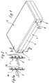
- the housing shown in Figures 1, 2 and 3 for receiving electrical or Electronic components consist essentially of a lower part 1 and one Upper part 2. Both the lower part 1 and the upper part 2 are advantageous made in one piece from plastic and also constructed identically. It is already pointed out at this point that the height of the lower part 1 can easily deviate from the height of the upper part 2.
- the outline of the housing is essentially in the illustrated embodiment rectangular, of course square versions are also conceivable.
- hinge and locking parts 3 are in the parting plane 4 between the lower part 1 and upper part 2 can be pivoted in a hinge-like manner, namely by a structurally defined one Film hinge 5.
- the hinge and locking parts 3 are provided with catches which snap into place in corresponding recesses 6 of the lower part 1 or Allow upper part 2.
- Locking is designed as locking webs 7 running parallel to the film hinge 5, wherein this construction offers the advantage that the hinge and closure parts Plastic, and that can be produced as extruded profiles.
- FIG. 2a shows that the detents 7a alternatively also as a push button Latches can be formed. It is understood that other forms of rest are conceivable.
- hinge and locking parts 3 are flush in the locking position within depressions 8 of the lower part 1 and the upper part 2, so that the Hinge and locking parts do not extend beyond the side walls of the housing protrude.
- the hinge and locking parts 3 and 3a thus perform two functions.
- these hinge and locking parts 3 are used for secure, closing Connection of lower part 1 and upper part 2, this connection by simple
- the notches are pressed into the notches.
- a Screwdriver 9 indicated in Figure 1 can now the hinge and locking parts 3 for example on one side of the housing in an open position brought while those arranged on the opposite side Hinge and locking parts remain in their locked position on both sides.
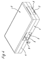
- the upper part 2 like a lid opposite the lower part 1 swing out, which is indicated in Figure 3 hint.
- With appropriate Elasticity of the film hinges 5 can the upper part 2 compared to the lower part 1 can be pivoted into a parallel position. If necessary, you can also use the lower part 1 and upper part 2 are completely separated from each other, it is then only necessary to loosen all used hinge and locking parts accordingly.
- Figure 4 shows that on two opposite sides only each a hinge and locking part 3 can be provided, it then it is recommended to increase the length of this hinge and locking part 3 choose a reliable hinge function if the upper part 2 to remain hinged to the lower part 1 during an opening process.
- Figure 4 also shows that in addition to the neighboring Frontal hinge and closure parts 3 can be provided, whereby at correspondingly large housings, the closing condition is also made more secure becomes.
- the housing according to the invention consists of extremely simple and inexpensive producible plastic parts and is - without functional impairment - light and quickly put it in a closed state and just as light and can also be opened completely or partially quickly.
Landscapes
- Engineering & Computer Science (AREA)
- Microelectronics & Electronic Packaging (AREA)
- Casings For Electric Apparatus (AREA)
- Elimination Of Static Electricity (AREA)
Abstract
Ziel der Erfindung ist die Schaffung eines derartigen Gehäuses, welches einfach und kostengünstig in der Herstellung ist und im Gebrauch einfach geöffnet und ebenso einfach vollständig verschlossen werden kann.
Zu diesem Zweck wird vorgeschlagen, daß mindestens an zwei einander gegenüberliegenden Seiten des Gehäuses Scharnier- und Verschlußteile (3) vorgesehen sind, welche sowohl in den Seitenwandungsbereich des Unterteiles (1) wie auch in den Seitenwandungsbereich des Oberteiles (2) eingeschnäppt und im Bereich der Trennebene (4) zwischen Unter- und Oberteil (1, 2) scharnierartig verschwenkbar sind.
Das Unterteil (1) und das Oberteil (2) können als relativ einfache Bauteile gestaltet werden, da keine besondere Rücksicht auf die Anbringung von Scharnieren und separaten Verschlußteilen genommen werden muß. Es ist lediglich sowohl beim Unterteil (1) wie auch beim Oberteil (2) dafür Sorge zu tragen, daß die erfindungsgemäß verwendeten Scharnier- und Verschlußteile (3) im jeweiligen Seitenwandungsbereich eingeschnäppt werden können. Hierfür genügen einfache Ausnehmungen oder Durchbrüche in den dafür vorgesehenen Seitenwandungsbereichen.
Description
- Figur 1
- eine perspektivische Darstellung eines erfindungsgemäßen Gehäuses im geschlossenen Zustand,
- Figur 2
- einen Schnitt nach der Linie II-II in Figur 1,
- Figur 2a
- einen der Figur 2 entsprechenden Schnitt durch ein Gehäuse nach einem weiteren Ausführungsbeispiel der Erfindung,
- Figur 3
- das in Figur 1 dargestellte Gehäuse im aufgeklappten Zustand,
- Figur 4
- eine perspektivische Darstellung eines geschlossenen Gehäuses nach einem weiteren Ausführungsbeispiel der Erfindung.
Claims (11)
- Gehäuse zur Aufnahnme elektrischer oder elektronischer Bauteile, bestehend aus einem Unterteil und einem Oberteil mit einem im wesentlichen rechteckigen oder quadratischen Grundriß, dadurch gekennzeichnet, daß mindestens an zwei einander gegenüberliegenden Seiten des Gehäuses Scharnier- und Verschlußteile (3) vorgesehen sind, welche sowohl in den Seitenwandungsbereich des Unterteiles (1) wie auch in den Seitenwandungsbereich des Oberteiles (2) eingeschnäppt und im Bereich der Trennebene (4) zwischen Unter-und Oberteil (1, 2) scharnierartig verschwenkbar sind.
- Gehäuse nach Anspruch 1, dadurch gekennzeichnet, daß an zwei gegenüberliegenden Seiten des Gehäuses jeweils ein Scharnier- und Verschlußteil (3) angebracht ist.
- Gehäuse nach Anspruch 1, dadurch gekennzeichnet, daß an zwei gegenüberliegenden Seiten des Gehäuses jeweils zwei oder mehrere Scharnier- und Verschlußteile (3) angebracht sind.
- Gehäuse nach Anspruch 1, dadurch gekennzeichnet, daß an allen Seiten des Gehäuses mindestens jeweils ein Scharnier- und Verschlußteil (3) angebracht ist.
- Gehäuse nach einem oder mehreren der vorhergehenden Ansprüche, dadurch gekennzeichnet, daß die Scharnier- und Verschlußteile (3) jeweils einstückig aus Kunststoff hergestellt und mit einem Filmscharnier (59 ausgestattet sind.
- Gehäuse nach Anspruch 5, dadurch gekennzeichnet, daß die Scharnierund Verschlußteile jeweils zu beiden Seiten des Filmscharnieres mit Rasten versehen sind, die in entsprechende Rastausnehmungen (6) innerhalb der Seitenwandungsbereiche von Unterteil (1) und Oberteil (2) eingeschnäppt sind.
- Gehäuse nach Anspruch 6, dadurch gekennzeichnet, daß die Rasten aus Raststegen (7) bestehen, welche parallel zum Filmscharnier (5) verlaufen.
- Gehäuse nach Anspruch 7, dadurch gekennzeichnet, daß die Raststege (7) jeweils symmetrisch zum Filmscharnier angeordnet sind.
- Gehäuse nach Anspruch 6, dadurch gekennzeichnet, daß die Rasten aus symmetrisch zum Filmscharnier angeordneten, druckknopfartigen Rastnocken (7a) bestehen.
- Gehäuse nach einem oder mehreren der vorhergehenden Ansprüche, dadurch gekennzeichnet, daß das Unterteil (1) und das Oberteil (2) aus baugleichen Teilen bestehen und aus Kunststoff gefertigt sind.
- Gehäuse nach einem oder mehreren der vorhergehenden Ansprüche, dadurch gekennzeichnet, daß die Scharnier- und Verschlußteile (3) im Verschlußzustand bündig innerhalb von Einsenkungen (8) des Unterteiles (1) und des Oberteiles (2) liegen.
Applications Claiming Priority (2)
| Application Number | Priority Date | Filing Date | Title |
|---|---|---|---|
| DE29720509U | 1997-11-19 | ||
| DE29720509U DE29720509U1 (de) | 1997-11-19 | 1997-11-19 | Gehäuse zur Aufnahme elektrischer oder elektronischer Bauteile |
Publications (2)
| Publication Number | Publication Date |
|---|---|
| EP0918451A2 true EP0918451A2 (de) | 1999-05-26 |
| EP0918451A3 EP0918451A3 (de) | 1999-12-29 |
Family
ID=8048829
Family Applications (1)
| Application Number | Title | Priority Date | Filing Date |
|---|---|---|---|
| EP98120453A Withdrawn EP0918451A3 (de) | 1997-11-19 | 1998-10-29 | Gehäuse zur Aufnahme elektrischer oder elektronischer Bauteile |
Country Status (2)
| Country | Link |
|---|---|
| EP (1) | EP0918451A3 (de) |
| DE (1) | DE29720509U1 (de) |
Cited By (2)
| Publication number | Priority date | Publication date | Assignee | Title |
|---|---|---|---|---|
| DE20116631U1 (de) * | 2001-10-11 | 2003-02-20 | Hörmann KG Antriebstechnik, 33790 Halle | Steuerungsgehäuse mit Schwenkmechanismus im Deckel |
| EP4314925A4 (de) * | 2021-03-26 | 2025-07-02 | Commscope Technologies Llc | Kommunikationstafelsysteme |
Families Citing this family (2)
| Publication number | Priority date | Publication date | Assignee | Title |
|---|---|---|---|---|
| DE102004009356B4 (de) * | 2004-01-20 | 2005-12-22 | Diehl Ako Stiftung & Co. Kg | Kunstoffgehäuse |
| DE102012215643A1 (de) | 2012-09-04 | 2014-03-06 | Robert Bosch Gmbh | Verschlussvorrichtung |
Family Cites Families (6)
| Publication number | Priority date | Publication date | Assignee | Title |
|---|---|---|---|---|
| US3592354A (en) * | 1969-11-03 | 1971-07-13 | Elmer T Nielsen | Hinge construction for two-piece containers |
| DE8607414U1 (de) * | 1986-03-18 | 1986-04-30 | Bündoplast bopla Gehäuse Systeme GmbH, 4980 Bünde | Gehäuse, insbesondere zum Einbau von elektrischen Bauteilen |
| US5381920A (en) * | 1993-12-21 | 1995-01-17 | Lin; Arlo H. T. | Tool box hinge structure |
| US5513909A (en) * | 1994-08-02 | 1996-05-07 | Maytag Corporation | Appliance hinge |
| DE29515499U1 (de) * | 1995-09-28 | 1996-01-04 | Endress + Hauser GmbH + Co, 79689 Maulburg | Gehäuse |
| DE19600260C1 (de) * | 1996-01-05 | 1997-05-28 | Rolec Gehaeusesysteme Rose & R | Innenscharnier zur Unterbringung im Verschraubungskanal von Gehäusen |
-
1997
- 1997-11-19 DE DE29720509U patent/DE29720509U1/de not_active Expired - Lifetime
-
1998
- 1998-10-29 EP EP98120453A patent/EP0918451A3/de not_active Withdrawn
Cited By (2)
| Publication number | Priority date | Publication date | Assignee | Title |
|---|---|---|---|---|
| DE20116631U1 (de) * | 2001-10-11 | 2003-02-20 | Hörmann KG Antriebstechnik, 33790 Halle | Steuerungsgehäuse mit Schwenkmechanismus im Deckel |
| EP4314925A4 (de) * | 2021-03-26 | 2025-07-02 | Commscope Technologies Llc | Kommunikationstafelsysteme |
Also Published As
| Publication number | Publication date |
|---|---|
| EP0918451A3 (de) | 1999-12-29 |
| DE29720509U1 (de) | 1999-04-01 |
Similar Documents
| Publication | Publication Date | Title |
|---|---|---|
| DE3711222C2 (de) | ||
| DE20015913U1 (de) | Steckverbinder für Hohlprofile | |
| DD299286A5 (de) | Verschluss mit schnappscharnier | |
| DE29724813U1 (de) | Bodenelement | |
| DE19817919A1 (de) | Rahmenschenkel für ein Rahmengestell eines Schaltschrankes | |
| DE4210953A1 (de) | Lastschaltleiste | |
| DE29623065U1 (de) | Rahmenprofil für ein Rahmengestell eines Schaltschrankes | |
| AT409995B (de) | Schlüssel für zylinderschloss | |
| EP0283973A2 (de) | Vorrichtung zur Befestigung von Gehäusen in Öffnungen einer Schalttafel oder einer Rastersystemwand | |
| EP0918451A2 (de) | Gehäuse zur Aufnahme elektrischer oder elektronischer Bauteile | |
| EP0918450B1 (de) | Aus Kunststoff hergestelltes Gehäuse für elektrische oder elektronische Bauteile | |
| DE69523579T2 (de) | Gehäuse für ein elektrisches Gerät | |
| DE60020055T2 (de) | Mobiles drahtloses Endgerät | |
| EP0162232B1 (de) | Schubkasten-Frontplatte | |
| DE3230312C2 (de) | ||
| DE19811048A1 (de) | Einrichtung zum Absorbieren des elektrischen Rauschens | |
| DE3115592C2 (de) | Verkehrssignalgeber mit Konstrastblende | |
| DE69321081T2 (de) | Gehäuse für ein tragbares Miniaturgerät | |
| DE3514276A1 (de) | Scharnierverbindung fuer extruderprofile | |
| EP0802551B1 (de) | Verriegelungseinrichtung für Sicherungseinsätze in einem Trennschalter | |
| DE29601355U1 (de) | Verbindungsknoten für Baukonstruktionen | |
| DE19903422A1 (de) | Schließblech | |
| EP0702383B1 (de) | Namenschildtaster | |
| DE939913C (de) | Scharnier mit in der Schliessstellung ineinander liegenden Scharnierplatten | |
| DE3515050C2 (de) |
Legal Events
| Date | Code | Title | Description |
|---|---|---|---|
| PUAI | Public reference made under article 153(3) epc to a published international application that has entered the european phase |
Free format text: ORIGINAL CODE: 0009012 |
|
| AK | Designated contracting states |
Kind code of ref document: A2 Designated state(s): AT BE CH CY DE DK ES FI FR GB GR IE IT LI LU MC NL PT SE |
|
| AX | Request for extension of the european patent |
Free format text: AL;LT;LV;MK;RO;SI |
|
| PUAL | Search report despatched |
Free format text: ORIGINAL CODE: 0009013 |
|
| AK | Designated contracting states |
Kind code of ref document: A3 Designated state(s): AT BE CH CY DE DK ES FI FR GB GR IE IT LI LU MC NL PT SE |
|
| AX | Request for extension of the european patent |
Free format text: AL;LT;LV;MK;RO;SI |
|
| RIC1 | Information provided on ipc code assigned before grant |
Free format text: 6H 05K 5/02 A, 6H 05K 5/00 B, 6E 05D 1/02 B |
|
| STAA | Information on the status of an ep patent application or granted ep patent |
Free format text: STATUS: THE APPLICATION HAS BEEN WITHDRAWN |
|
| 18W | Application withdrawn |
Withdrawal date: 20000303 |